US2463243A - Wrist watch band - Google Patents
Wrist watch band Download PDFInfo
- Publication number
- US2463243A US2463243A US598875A US59887545A US2463243A US 2463243 A US2463243 A US 2463243A US 598875 A US598875 A US 598875A US 59887545 A US59887545 A US 59887545A US 2463243 A US2463243 A US 2463243A
- Authority
- US
- United States
- Prior art keywords
- straps
- band
- wrist
- portions
- wrist watch
- Prior art date
- Legal status (The legal status is an assumption and is not a legal conclusion. Google has not performed a legal analysis and makes no representation as to the accuracy of the status listed.)
- Expired - Lifetime
Links
Images
Classifications
-
- A—HUMAN NECESSITIES
- A44—HABERDASHERY; JEWELLERY
- A44C—PERSONAL ADORNMENTS, e.g. JEWELLERY; COINS
- A44C5/00—Bracelets; Wrist-watch straps; Fastenings for bracelets or wrist-watch straps
- A44C5/14—Bracelets; Wrist-watch straps; Fastenings for bracelets or wrist-watch straps characterised by the way of fastening to a wrist-watch or the like
- A44C5/145—Hooks
Definitions
- This invention relates to wrist watch bands, and is more particularly concerned with an allmetal type of band construction.
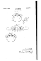
- Fig. l is a view partly in side elevation and partly in section of a wrist watch band made in accordance with my invention, indicating in dotted lines a wrist watch case held in place between the adjustable straps;
- Fig. 2 is a developed plan View of a band like that shown in Fig. 1, but with the straps nearly fully retracted as for application to a longer case;
- Fig. 3 is a view corresponding to a portion of Fig. 1, showing a modified or alternative construction of the attaching end of the strap, and
- Fig. 4 is a view similar to Fig. 1, showing a different type of strap, one of the straps being shown applied to a watch case and the other strap in retracted position preparatory to attachment to the case.
- the band a is C-shaped and of one-piece flexible spring metal construction adapted to be spread enough to pass the open side sidewise over the wrist.
- the band once in place on the wrist, is not apt to fall off or slip off accidentally.
- the band has two transverse loop portions 9 and Hi punched out of the plane thereof on opposite sides of the flat widened front middle portion I of the band, through which adjustable short metal straps l2 and i3 are slidable, these straps being arcuate in longitudinal section, to conform approximately to the curvature of the opposed side portions hi and l5 of the band.
- the inner ends of the straps are bent to U-shaped section to provide bearing portions l6 and I: adapted to receive the conventional type of pins for detachably securing the straps to the opposite ends of a wrist watch case,
- I mean, of course, the well known pins having spring pressed plungers projecting from the ends thereof for entry into the small sockets provided therefor in the inner sides of the forked ends IQ of the watch cases.
- the straps l2 and E3, in accordance with my invention, are entered in the forked ends of the watch case and fastened by means of these pins, after which the watch case is centered between the loops 9 and lo, and the loops are then compressed or flattened to a slight extent sufficient to grip the straps l2 and I3 firmly in the adjusted position.
- I may as a part of the flattening operation on the loops 9 and I0 imprint initials or monograms, as indicated, for example, at 29 in Fig. 2, or these initials could be engraved in the loops before or after the flattening thereof.
- I have indicated in the sectioned portion of Fig. 1 the displacement of metal in the loop and strap produced by the imprinting dies.
- the straps l2 and it are not projected as far from the loops 9 and it, but the same mode of clenching is illustrated.
- the clenching holds the watch securely enough to eliminate likelihood of its shifting endwise, but it is obvious that a jeweler may, if occasion should later require it, force the straps endwise in either direction if it is desired to use the band on another watch that may require a different adjustment of the straps.
- the strap l2 indicated in Fig. 3, cooperates with the looped portion 9 of the band 8 in a similar way as the straps l2 and E3 in Figs. 1 and 2, but has the bearing portion l6 thereof curled upwardly to accommodate the conventional attaching pin.
- the band. B is of the same construction as that above described, having looped portions 9 and ID on opposite sides of the widened front middle portion M.
- the straps l2a and lfia are of thin spring material which if removed from the loops 9 and m would tend to coil up like a clock spring. These straps are uncoiled and slipped through the looped portions 9 and Ill of the band so that the outer end portions 2
- Embossed bead portions 22 may be formed in the outer end portions of the straps after they have been assembled in the loops of the band, so as to leave the same length of strap projecting beyond each of the loops, as illustrated in Fig. 4.
- the inner end portions 23 of these straps which are curled, are adapted te r feceive the attaching pins for attachment of "the straps to the ends of the watch case l8a, and thestraps are uncoiled enough to make the connections, after which the watch case will be held substantially centrally between the looped portions of the band under the substantially equal but opposite spring tensions of the straps, the beads '22 on the straps preventing inward displacement thereof.
- the strap iza is shown in the attached position and the strap I20, in retracted position preparatory to the attachment thereof.
- a band for supporting a watch or other article on the wrist and having attaching means at opposite ends thereof said band comprising a onepiece c-shaped member of flat, thin, resilient metal adapted to encircle the wrist, said member having two spaced loop portions formed from the metal of said member bent bodily upwardly out of the plane of the metal in substantially parallel relation to one another and to the plane of said metal and spaced from the attaching means on opposite ends of said article, whereby the inner surface of the band that comes in contact with the wrist is smooth and devoid of projections, and two short metallic straps disposed wholly on the outer side of the band slidably mounted on top of said band member while confined closely within said loop portions, permitting adjustment of said straps toward and away from one another for connection interchangeably to articles of different length entered between the adjoining ends thereof, said adjoining ends of said straps being constructed for connection to said attaching means, said loop portions being disposed in close contact with the tops of said straps and having portions thereof struck therefrom to frictionally grip the straps in adjusted positions.
Description
March 1, 1949. J. H. CARTER WRIST wA'rcH BAND Ffiled June 11, 1945 Patented Mar. 1, 1949 UNITED STATES PATENT OFFlCE WRIST WATCH BAND Joseph H. Carter, Rockford, Ill. Application June 11, 1945, Serial No. 598,875
1 Claim. 1
This invention relates to wrist watch bands, and is more particularly concerned with an allmetal type of band construction.
I am aware that C-shaped metal bands of flexible spring material have been used to some extent, but it has been a problem to provide satisfactory means for fastening the watch case to the band, and the means heretofore devised have all been subject to certain objections. It is, therefore, the principal object of my invention to provide a metal band so constructed that short metal straps attached to the opposite ends of the watch case may be held securely without detracting from the neatness and good appearance of the ensemble or giving rise to any inconvenience or discomfort to the wearer.
The invention is illustrated in the accompanying drawings, in which- Fig. l is a view partly in side elevation and partly in section of a wrist watch band made in accordance with my invention, indicating in dotted lines a wrist watch case held in place between the adjustable straps;
Fig. 2 is a developed plan View of a band like that shown in Fig. 1, but with the straps nearly fully retracted as for application to a longer case;
Fig. 3 is a view corresponding to a portion of Fig. 1, showing a modified or alternative construction of the attaching end of the strap, and
Fig. 4 is a view similar to Fig. 1, showing a different type of strap, one of the straps being shown applied to a watch case and the other strap in retracted position preparatory to attachment to the case.
Similar reference numerals are applied to corresponding parts throughout the views.
Referring first to Figs. 1 and 2, the band a is C-shaped and of one-piece flexible spring metal construction adapted to be spread enough to pass the open side sidewise over the wrist. The band, once in place on the wrist, is not apt to fall off or slip off accidentally. The band has two transverse loop portions 9 and Hi punched out of the plane thereof on opposite sides of the flat widened front middle portion I of the band, through which adjustable short metal straps l2 and i3 are slidable, these straps being arcuate in longitudinal section, to conform approximately to the curvature of the opposed side portions hi and l5 of the band. The inner ends of the straps are bent to U-shaped section to provide bearing portions l6 and I: adapted to receive the conventional type of pins for detachably securing the straps to the opposite ends of a wrist watch case,
like that indicated in dotted lines at M in Fig. 1. By conventional pins, I mean, of course, the well known pins having spring pressed plungers projecting from the ends thereof for entry into the small sockets provided therefor in the inner sides of the forked ends IQ of the watch cases. The straps l2 and E3, in accordance with my invention, are entered in the forked ends of the watch case and fastened by means of these pins, after which the watch case is centered between the loops 9 and lo, and the loops are then compressed or flattened to a slight extent sufficient to grip the straps l2 and I3 firmly in the adjusted position. If desired, I may as a part of the flattening operation on the loops 9 and I0 imprint initials or monograms, as indicated, for example, at 29 in Fig. 2, or these initials could be engraved in the loops before or after the flattening thereof. I have indicated in the sectioned portion of Fig. 1 the displacement of metal in the loop and strap produced by the imprinting dies. Where the watch case is longer, like the watch case I8 shown in Fig. 2, the straps l2 and it are not projected as far from the loops 9 and it, but the same mode of clenching is illustrated. The clenching holds the watch securely enough to eliminate likelihood of its shifting endwise, but it is obvious that a jeweler may, if occasion should later require it, force the straps endwise in either direction if it is desired to use the band on another watch that may require a different adjustment of the straps.
The strap l2, indicated in Fig. 3, cooperates with the looped portion 9 of the band 8 in a similar way as the straps l2 and E3 in Figs. 1 and 2, but has the bearing portion l6 thereof curled upwardly to accommodate the conventional attaching pin.
In the construction shown in Fig. 4, the band. B is of the same construction as that above described, having looped portions 9 and ID on opposite sides of the widened front middle portion M. In this construction, however, the straps l2a and lfia are of thin spring material which if removed from the loops 9 and m would tend to coil up like a clock spring. These straps are uncoiled and slipped through the looped portions 9 and Ill of the band so that the outer end portions 2| lie in snug contact with the curved side portions l4 and E5 of the band under the inherent resilience of the material of the straps. Embossed bead portions 22 may be formed in the outer end portions of the straps after they have been assembled in the loops of the band, so as to leave the same length of strap projecting beyond each of the loops, as illustrated in Fig. 4. Now, the inner end portions 23 of these straps, which are curled, are adapted te r feceive the attaching pins for attachment of "the straps to the ends of the watch case l8a, and thestraps are uncoiled enough to make the connections, after which the watch case will be held substantially centrally between the looped portions of the band under the substantially equal but opposite spring tensions of the straps, the beads '22 on the straps preventing inward displacement thereof. In Fig. 4 the strap iza is shown in the attached position and the strap I20, in retracted position preparatory to the attachment thereof.
It is believed the foregoing description conveys a good understanding of the objects andadvantages of my invention. The appended claim has been drawn to cover all legitimate modifications and adaptations.
I claim:
A band for supporting a watch or other article on the wrist and having attaching means at opposite ends thereof, said band comprising a onepiece c-shaped member of flat, thin, resilient metal adapted to encircle the wrist, said member having two spaced loop portions formed from the metal of said member bent bodily upwardly out of the plane of the metal in substantially parallel relation to one another and to the plane of said metal and spaced from the attaching means on opposite ends of said article, whereby the inner surface of the band that comes in contact with the wrist is smooth and devoid of projections, and two short metallic straps disposed wholly on the outer side of the band slidably mounted on top of said band member while confined closely within said loop portions, permitting adjustment of said straps toward and away from one another for connection interchangeably to articles of different length entered between the adjoining ends thereof, said adjoining ends of said straps being constructed for connection to said attaching means, said loop portions being disposed in close contact with the tops of said straps and having portions thereof struck therefrom to frictionally grip the straps in adjusted positions.
JOSEPH H. CARTER.
REFERENCES CITED UNITED STATES PATENTS Name Date Eccleston Aug. 4, 1908 FOREIGN PATENTS Country Date Germany Apr. 17, 1941 Number Number
Priority Applications (1)
| Application Number | Priority Date | Filing Date | Title |
|---|---|---|---|
| US598875A US2463243A (en) | 1945-06-11 | 1945-06-11 | Wrist watch band |
Applications Claiming Priority (1)
| Application Number | Priority Date | Filing Date | Title |
|---|---|---|---|
| US598875A US2463243A (en) | 1945-06-11 | 1945-06-11 | Wrist watch band |
Publications (1)
| Publication Number | Publication Date |
|---|---|
| US2463243A true US2463243A (en) | 1949-03-01 |
Family
ID=24397277
Family Applications (1)
| Application Number | Title | Priority Date | Filing Date |
|---|---|---|---|
| US598875A Expired - Lifetime US2463243A (en) | 1945-06-11 | 1945-06-11 | Wrist watch band |
Country Status (1)
| Country | Link |
|---|---|
| US (1) | US2463243A (en) |
Cited By (3)
| Publication number | Priority date | Publication date | Assignee | Title |
|---|---|---|---|---|
| DE964002C (en) * | 1954-12-09 | 1957-05-16 | Wilhelm Kolb Fa | Clip bracelet for watches |
| DE1114052B (en) * | 1959-07-22 | 1961-09-21 | Karl Heinrich Heinz | Clip bracelet for wristwatch |
| USD928012S1 (en) * | 2020-02-28 | 2021-08-17 | Wisecrack LLC | Watch strap |
Citations (2)
| Publication number | Priority date | Publication date | Assignee | Title |
|---|---|---|---|---|
| US895352A (en) * | 1907-01-26 | 1908-08-04 | Gurnsey B Williams | Cake-turner. |
| DE705065C (en) * | 1939-02-09 | 1941-04-17 | Wilhelm Speer | Watch strap with a springy metal band forming an open ring |
-
1945
- 1945-06-11 US US598875A patent/US2463243A/en not_active Expired - Lifetime
Patent Citations (2)
| Publication number | Priority date | Publication date | Assignee | Title |
|---|---|---|---|---|
| US895352A (en) * | 1907-01-26 | 1908-08-04 | Gurnsey B Williams | Cake-turner. |
| DE705065C (en) * | 1939-02-09 | 1941-04-17 | Wilhelm Speer | Watch strap with a springy metal band forming an open ring |
Cited By (3)
| Publication number | Priority date | Publication date | Assignee | Title |
|---|---|---|---|---|
| DE964002C (en) * | 1954-12-09 | 1957-05-16 | Wilhelm Kolb Fa | Clip bracelet for watches |
| DE1114052B (en) * | 1959-07-22 | 1961-09-21 | Karl Heinrich Heinz | Clip bracelet for wristwatch |
| USD928012S1 (en) * | 2020-02-28 | 2021-08-17 | Wisecrack LLC | Watch strap |
Similar Documents
| Publication | Publication Date | Title |
|---|---|---|
| US3225565A (en) | Pearl slide shortener and pin adaptor | |
| US2002946A (en) | Buckle and process of making same | |
| US2159223A (en) | Extension key chain | |
| US2013760A (en) | Clasp | |
| US3271977A (en) | Jewelry shortener lock with pin | |
| US1658053A (en) | Bracelet | |
| US2463243A (en) | Wrist watch band | |
| US2447422A (en) | Chain clasp | |
| US2246091A (en) | Key chain construction | |
| US1692079A (en) | Automatic strap tightener | |
| US2490908A (en) | Earring | |
| US2548140A (en) | Jewelry attachment | |
| US2622292A (en) | Buckle or strap fastening | |
| US1784482A (en) | Lingerie clasp | |
| US2669102A (en) | Ear ornament | |
| US2222053A (en) | Spring ring | |
| US2191314A (en) | Wrist watch strap construction | |
| US1673117A (en) | Fastening device for straps, bands, and bracelets | |
| US3319308A (en) | Jewelry clasp | |
| US2148629A (en) | End clasp for bracelets and the like | |
| US2924827A (en) | Buckle construction with decorative panel | |
| US1701060A (en) | Clasp for watch bracelets | |
| US2018068A (en) | Connecter or fastening device for chain bracelets | |
| US1850722A (en) | Fastening-device for wrist-watch straps, bands, bracelets, and the like | |
| US3402438A (en) | Pin stem clasp |