US2568933A - Mounting and operating means for electric switches - Google Patents
Mounting and operating means for electric switches Download PDFInfo
- Publication number
- US2568933A US2568933A US32883A US3288348A US2568933A US 2568933 A US2568933 A US 2568933A US 32883 A US32883 A US 32883A US 3288348 A US3288348 A US 3288348A US 2568933 A US2568933 A US 2568933A
- Authority
- US
- United States
- Prior art keywords
- switch
- bushing
- adapter
- pushbutton
- base
- Prior art date
- Legal status (The legal status is an assumption and is not a legal conclusion. Google has not performed a legal analysis and makes no representation as to the accuracy of the status listed.)
- Expired - Lifetime
Links
Images


Classifications
-
- H—ELECTRICITY
- H01—ELECTRIC ELEMENTS
- H01H—ELECTRIC SWITCHES; RELAYS; SELECTORS; EMERGENCY PROTECTIVE DEVICES
- H01H13/00—Switches having rectilinearly-movable operating part or parts adapted for pushing or pulling in one direction only, e.g. push-button switch
- H01H13/02—Details
- H01H13/12—Movable parts; Contacts mounted thereon
- H01H13/20—Driving mechanisms
Description
Sept 25, 1951 c. F. ROBBINS 2,568,933
MOUNTING AND OPERATING MEANS FOR ELECTRIC SWITCHES @Ag 509 376 575' 47 50e of Sept. 25, 1951 C. F. ROBBINS MOUNTING AND OPERATING MEANS FOR ELECTRIC SWITCHES Original Filed July 4, 1942 oqa 63 3 Sheets-Sheet 2 sai o9 7oal 'lod 'rob Sept 25, 1951 c. F. RoBBlNs 2,568,933
MOUNTING AND OPERATING MEANS FOR ELECTRIC SWITCHES Original Filed July 4, 1942 3 Sheets-Sheet 5 Patented Sept. 25, 1951 UNITED STATES PATENT OFFICE MOUNTING AND OPERATING MEANS FOR ELECTRIC SWITCHES Clyde F. Robbins, Milwaukee, Wis., assignor to Cutler-Hammer, Inc., Milwaukee, Wis., a corporation of Delaware (Cl. ZOO-17) '7 Claims.
This invention relates to improvements in mounting and operating means for electric switches, and especially for manually operable switches of the reciprocating contacter type.
A primary object of the invention is to provide various novel and simple forms of adapters for use with electric switches of the aforementioned character, whereby the latter are adapted for various forms of mountings, such as base mounting, one-hole mounting, cover mounting, and for mounting on panels of various thicknesses.
Another object is to provide a novel form of mushroom-head type of operator for switches of the aforementioned character.
Other objects and advantages of the invention will hereinafter appear.
This application is a division of my Patent No. 2,460,034, granted January 25, 1949, for Electric Switches, and assigned to the same assignee as the present application.
The accompanying drawings illustrate certain embodiments of my invention which will now be described, it being understood that my invention isA susceptible of embodiment in other forms without departing from the scope of the appended claims.
In the drawings,
Figure 1 is a side elevational view of a manually operable switch of the reciprocating contactor type having one of my novel adapter members associated therewith to provide for base mounting of the switch.
Fig. 2 is a central vertical sectional view of the switch and adapter member shown in Fig. 1, in a plane parallel to the elevational view of Fig. 1; portions of the enclosing casing or housing being shown in dotted lines.
Fig. 3 is a central vertical sectional view, on the line 3-3 of Fig. 1, looking in the direction of the arrows, illustrating certain additional structural features of the adapter member.
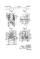
Fig. 4 is a side elevational view of a modification, wherein substitute parts are employed to provide for one-hole mounting of the switch; a relatively long pushbutton being shown in full lines, and an alternative shorter form of pushbutton being indicated by dotted lines.
Fig. 5 is a side elevational view, at a right angle to that of Fig. 4, with the one-hole mounting adapter parts and the upper end portion of the insulating base shown in vertical section, and with another portion of the base broken away to show the contactors engaged with the lower contacts as an incident to depression of the pushbutton.
Fig. 6 is a fragmentary side elevational view similar to Fig. 4, but showing a mushroom-head type of operator in combination with a one-hole mounting type of Switch.
Fig. '7 is a side elevational view somewhat like Fig. 1, but showing a mushroom-head type of operator in combination with a base mounted type of switch, portions of the operator and the one-hole mounting means therefor being shown in Vertical section, and only upper and lower fragments of the insulating base being illustrated. n
Fig. 8 is a vertical sectional view, on the line 8-8 of Fig. 6, the upper end portion of the base, the plunger, and portions of the operator being shown in elevation.
Fig. 9 is a top plan view of a cast metal flush plate, to the inner surface of which a pushbutton switch may be attached.
Fig. 10 is a vertical sectional view, on the line |0-I0 of Fig. 9, showing the manner of attaching the switch base to the flush plate, a fragment only of the insulating base being shown in elevation.
Fig. 11 is a vertical sectional view of the adapter elements employed for attaching a switch, having a mushroom-head type of operator, to supporting panels up to two inches in thickness, a fragment of the switch base being shown in elevation, and
Fig. 12 is a view similar to Fig. 11, but showing the adapter elements employed for attaching a pushbutton type of switch to panels up to two inches in thickness.
Referring first to the base mounted switch illustrated in Figs. 1, 2 and 3, the numeral 35 designates the one-piece molded insulating base, which is common to all forms of switches herein contemplated. Base 35 is adapted to be produced in a suitable multi-part hot-molding die (not shown); a very high grade Bakelite molding composition preferably being employed. The structural details of base 35, plunger 31, and the contactor and contact parts associated therewith are more fully described in my aforementioned Patent No. 2,460,034; corresponding parts in the two applications having like numerals of reference applied thereto. Thus numeral 36 desighates a spirally-wound, cone-shaped, compression spring, which is interposed between the bottom wall of a recess in base 35 and the lower end of a molding insulating plunger 31 carrying contactors 43 for cooperation with stationary contacts 39, 40. Plunger 31 has an upward extension 31n to which a pushbutton 41 is removably attached. Pushbutton 41 is provided adjacent its lower end with an annular flange 41d having four symmetrically arranged notches, two of which are shown at 41e, 41e in Fig. The functions of the portions 35h, 39C, 35d, 4Gb, 40C, 40d, 4l and 4ia of the combined stationary contact and wiring terminal members 39 and 49 (Fig. 1) are described in detail in said Patent No. 2,460,034; said members being attached to base 35 by suitable screws, the shanks of which are designated by numeral 38a.
A flat, punched sheet metal guide plate 48 is provided with a circular opening 48a (Figs. 2 and 3) to slidably accommodate and guide the pushbutton 41 to assist in restricting the latter to reciprocating movement in a straight line, said plate being .provided at opposite sides thereof with lugs having U-shaped notches formed therein, as shown at 48d and 48e in Fig. 2. Plate 48 is adapted to seat against the upper ends of' extensions 351l and 35h, the latter having downwardly offset ledges 35i' and 35Z (Fig. l) to accommodate a portion of the thickness of said lugs and the adjacent peripheral portions of plate 48. The functions of the portions 35g, 35h, 35i, 353, 35k, 351, 35S, 35i, and 35V are described in detail in the aforementioned Patent No. 2,460,034.
The switch parts thus far described may be assembled in the manner described in detail in my aforementioned Patent No. 2,460,034. After the desired or required number and location of pairs of contacts and contactors has been effected, the pushbutton 4'.' is pressed onto the plunger extension 31n (the spring ring 46, Fig. 2, having been previously assembled upon the reduced end 31p of said extension) and the plate 48 is positioned upon the upper ends of the extensions and 35b to surround the pushbutton and to overlie the flange 41d on the latter (Figs. 2 and 3).
Thereafter an adapter member 59 of substantially annular form is positioned over plate 43 and is adapted to seat against the latter throughout the annular overlapping portions of parts. As indicated at 50a and 5!)b in Fig. 2 the lower end portions of lateral extensions 50C and 5l)d of member l extend downwardly a slightly greater distance than the main body thereof, the downwardly extending portions being formed to closely surround or fit the aforementioned lugs on plate 48, to assist in preventing relative lateral movement between said parts. Member 50 preferably consists of a zinc base metal die casting, although die castings of other suitable or desired compositions may, of course, be employed.
The aforementioned pushbutton 41 is preferably provided with a concave upper surface 41b (Fig. 2), which may be provided with an indicating legend (not shown). The recess 41n in pushbutton 41 accommodates plunger extension 31n with a rather close fit; and said parts are frictionally held together' by the action of spring ring 46. The beveled lower end 41c of pushbutton 41 facilitates telescoping of the latter onto extension 31H.
The functions of the respective portions 31H, 31h, 31, 31d, 31, 31f, 31i, 311, 31k, 311, 31m, 31s and 31t are more or less obvious, and are described in detail in the aforementioned Patent No. 2,400,034.
The switch of Figs. 4 and 5 is of the pushbutton type and is adapted for one-hole mounting. Fo:- this purpose an adapter is provided. Adapter G9 is exteriorly the same as adapter 5-Il aforedescribed, and accordingly one part of the casting die may be employed in forming both adapters 58 and '60. However, different core portions are required for forming the respective adapters. Thus adapter 60 is provided with a central circular opening which is of substantially larger diameter than the opening 5i)e in adapter 50. Said opening in adapter 60 is tapped, as shown at 66a in Fig. 5, to cooperatively receive the externally threaded lower end portion Sla of a hollow bushing (El, the enlarged upper end of which is vertically milled peripherally throughout the major portion of its height to facilitate rotation thereof, either manually or otherwise, into clamping position; said enlarged end having a horizontal shoulder SIC (Fig. 5) to act as a clamping surface.
Interposed between said shoulder 61C and the upper surface of a panel or cover member 63, here shown as composed of metal, is a punched and stamped sheet metal indicating plate 64.
. Plate 54 is provided with a circular opening 84a (Fig. 5) to accommodate portion Gla of bushing 6l, and said plate is provided with an integral lug bent downwardly at a right angle thereto, as shown at 64b in Fig. 4, to nt into a recess of substantially corresponding size, as shown in dotted lines at 601 in said figure, whereby plate 64 is restrained against relative rotary displacement. As shown in Fig. 4, member 63 is provided with an opening 63a to provide clearance for lug 64b, and member 63 is also provided with an opening 63b to afford clearance for the lower end portion 6|' of bushing 6|. The horizontal surface portion 6l!b of adapter 60 underlies a portion of member 63 around the opening 63b in the latter, whereby adapter 6U is clamped to member 63. Adapter 60 is likewise provided with a pair of tapped openings 60h and 601, which are of relatively smaller diameter than the aforedescribed untapped openings 50h and 501 of adapter 50 (see Fig. 2). Said tapped openings 60h and (il)i are respectively adapted to receive the threaded upper ends of a pair of screws or bolts 65, 65, the heads of which are located in the countersinks 35k and 35l (Fig. 5) in the lower surface of base 35. The top surface of portion 64c (Fig. 4) of member 64 may have any suitable or desired legend imprinted, embossed, engraved or otherwise applied thereto, to correspond with the electrical characteristics or functions of the particular switch.
The pushbutton 66 in Figs. 4 and 5 is substantially longer than the pushbutton 41 of Figs. 1 to 3. Pushbutton 66 requires the additional length not only because of the added length of the assembly occasioned by the use of bushing 6I, but also because of the fact that it is desir-ed to have a greater length of the upper end of pushbutton 66 expo-sed in the normal position of the latter, as best illustrated in Fig, 4. If desired, a relatively shorter pushbutton may be employed in the device of Figs. 4 and 5, as indicated in dotted lines at 61 in Fig. 4. The pushbutton 61 is also substantially longer than the pushbutton 41 of Figs. 1 to 3. Except for the diiferences in length, the pushbuttons 66 and 61 may be the same as the pushbutton 41. It follows that all of the pushbuttons 41, B6 and 61 may be formed in molding dies having -certain parts thereof identical, different Icore members only being required to produce the relatively longer plunger-end-receiving recesses in pushbuttons 66 and 61.
Except for the illustrated arrangement of terminals in Figs. 4 and 5, whereby it is possible to use like combined contact and terminal members, 39, for the entire switch, it is to be understood that the elem-ents of such switch not mentioned may be identical with the corresponding elements of the switch of Figs. 1 to 3.
In the modication illustrated in Figs.y 6 and 8 it is to be understood that the insulating base 35 may have any desired arrangement'of the aforedescribed stationary contact and terminal members and bridging contactors. This switch is of the one-hole mounting type having a mushroom-head type of operator. Accordingly I prefer to employ an adapter member 60 identical with the adapter of Figs. 4 and 5. A metal bushing 68 has an externally threaded lower end portion 68a which penetrates the panel opening 63b and takes into the tapped opening 60a in adapter 6U, Bushing 68 is provided with an enlarged upper end portion 68la preferably of hexagonal form in transverse cross section, as best illustrated in Fig. 6. Bushing 68 is also provided at its lower end with a relatively large, centrally located, downwardly opening recess 68C, Fig. 8; and a passage 68d, of relatively smaller diameter than but alined with said recess, extends to the upper end of said bushing.
The mushroom-head operator includes a cylin- 6 drical shank member 69 which is adapted for a free but relatively close sliding fit within the bushing passage 68d. A stamped sheet metal head 10 of 4circular contour has Yits concave or dished lupper surface portion alined with and rigidly attached to the upper end of shank member 69, as by spot-welding, as indicated at 10a. Head 10 has an annular downwardly curved portion 16d, an voutwardly curved portion 10b adjacent thereto, and a vertically downwardly extending skirt portion 10c, which is of a diameter to clear the enlarged portion 68b of bushing 68.
The shank portion 69 is provided at its lower end with a drilled and tapped recess 692L to receive the shank 1|3L of a specially formed bolt, the hexagonal head of which is designated by numeral 1lb (Fig. 8). A split lock-washer 12, of smaller diameter than shank member 69, is preferably interposed between the lower end of the latter and the bolt head 1lb, to restrain said bolt against accidental loosening. Bolt head 1Ib underlies the end wall of recess 68c to prevent accidental manual removal of shank member 69 from bushing 68, whereas, as shown in Fig. 8, said bolt head 1|b is normally spaced downwardly to a slight degree from said end wall of recess 68C. Formed integrally with and located centrally upon the lower surface of bolt head 1Ib is a relatively short, cylindrical, downward extension 1|c which is adapted to abut against the at, square upper surface of the portion 31p of plunger extension 31.
A flat, punched sheet metal plate 13, having a thickness and peripheral contour identical with those of plate 48 aforedescribed, is provided with a central circular opening 138- of a diameter to accommodate the plunger extension 31n and the downward extension 11 of bolt head 1lb, but smaller than the peripheral contour of said bolt head; wherefore the lower surface of the latter is adapted to abut against the upper surface of plate 13, upon depression of the mushroom-head, to positively limit the degree of inward movement of extension 1|c against the plunger 31. In this manner any possible injury to the contacts and contactors, or to the plunger 31 carrying the latter, is insured against, in the event of excessive pressure being applied to the `mushroom-head operator. The insulating base 35 with its associated parts is rigidly attached to adapter member 6D as by means of the pair of bolts 65, in the manner described in connection with Figs. 4
and 5.
The horizontal annular shoulder 68e is adapted to seat against the upper surface of a panel of a suitable thickness to insure the proper distance of the end wall of recess 68C from the extension 31Kl of plunger 31 in the normal position of the latter, but where a relatively thin panel 63 is employed I prefer to interpose between said shoulder (i8e and the upper surface of the panel a metal washer or washers of suitable thickness, as shown at 14 and 15. By this means proper normal (or upper extreme) positioning of plunger 31, under the bias of spring 36 aforedescribed, may be insured.
The switch shown in Fig. 1 includes most of the parts of the switch shown in Figs. 6 and 8, and such parts have been given corresponding numerals of reference. In Fig. '1, however, the base 35 is adapted to be attached to a rear panel or casing wall 16 as by means of a pair of bolts 11, 11 of suitable length; the heads 11a of said bolts being adapted to overlie the opposite notched ends or extensions v13b and 13C of plate 13 to provide for clamping of base 35 in position. A pair of lock-washers 18, 18 preferably underlie the heads of bolts 11 to prevent accidental loosening thereof.
The front panel or cover member 63 in Fig. 7 is adapted to be spaced at such a distance from the rear panel 16 that the extension 1|c of bolt head 1 I b may rest against the end portion 31p of plunger 31 without aifecting the outward (or upward) bias upon the latter afforded by the aforementioned spring 36. As will be noted, the mushroom-head operating elements in Fig. 7 are supported by panel 63 substantially in the manner disclosed in Figs. 6 and 8, whereas the insulating base 35 with its associated parts is attached to panel 16, as aforedescribed. I therefore provide in the panel 63 in Fig. 7 a circular opening 63c which is of relatively larger diameter than the aforedescribed opening 63h (Fig. 8). Said opening 63c is adapted to provide rotating clearance for the upwardly extending annular flange 19a of a bushing or washer 19, which is preferably of square or other polygonal contour to provide for engagement thereof by a wrench or similar tool, washer 19 being internally threaded, as indicated at 19D, for cooperation with the reduced and threaded portion 68al of bushing 68.
In order to properly locate bushing 68 vertically with respect to plunger 31 of the switch in Fig. 7, I prefer to employ a pair of washers 14, only one washer of that thickness being employed in the switch of Figs. 6 and 8.
Referring more specically to the mushroomhead operator shown in each of Figs. 6 to 8, it will be noted that bushing 68 is provided at its upper end with an integral extension 68f (Figs. 7 and 8) of reduced diameter, said extension being dened by a neck portion E8g of concave form in vertical cross-section and an adjacent overhanging end portion |58h of convex form in vertical cross section. The skirt portion 1l)C of the mushroom-head is adapted to overlap the dat upper end surface 68i of bushing 68 to some extent, even in the outer extreme position of said mushroom-head. Hence these parts cooperate to prevent direct access to the shank 69 of thrown globules or particles of oil or grease; whereas the relatively close sliding t of shank 69 within passage 68d in bushing 68 further assists in preventing access of oil, grease or other foreign matter to the contacts and contactors associated with base 35. This arrangement is especially effective when, as usual, the switch is mounted with the height of the base 35 extending in a horizontal plane.
In Figs. 9 and 10 I have shown a switch may be like that shown in Figs. 1 to 3, except that a flush plate S3 has been substituted for the adapter member of Figs. l to 3, and screws 65, (like those of Figs. 4 and 5) are utilized to secure switch base 35 and its associated parts, including pushbutton 41, to plate 83, instead of using the base-mounting screws 52, 52 of Figs. l to 3. The plate 48 of Figs. l to 3 is employed in the device of Figs. 9 and l0 to positively limit the degree of outward movement of pushbutton 41, although, as aforedescribed, pushbutton 41 will normally be frictionally held to the plunger by the aforementioned spring ring 46, whereas the movable contactor or contactors will cooperate with the upper stationary contacts to limit the degree of outward movement of said plunger.
The mushroom-head operated switch shown in Fig. 1l is adapted for mounting upon panels up to two inches in thickness, and most of the parts thereof may be identical with the corresponding parts of the switch shown in Figs. 6 and 8, which parts have been given numerals of reference. Thus the mushroom head 1D, shank 69, lockwasher 12, adapter member 60, plate 13, and the base 35 with its associated parts, including plunger 31 are the same in both devices. However, in Fig. 11 I have shown a bushing 84 which is similar to the aforedescribed bushing 68, except that bushing 84 is provided with a relatively longer reduced lower end portion 848, which is externally threaded throughout the major portion of its length for cooperation with the internally threaded portion SJa of member 60.
The panel 86 in Fig. l1 is shown as composed of suitable insulating material, the same having a circular opening 86a to accommodate the lower end portion 84a of bushing 84. Panel 86 is provided in its lower face with a relatively large circular countersink or recess 86b which is adapted to freely receive a portion of the length of adapter member 60. Recess 86b is concentric with passage 861; and said recess 86b is provided at diametrically opposite predetermined points with a pair of drilled recesses 86c and 86d, which are respectively adapted to accommodate the relatively long threaded shank portions of a pair of screws 81, which penetrate the tapped openings 60h and 60i in member 60 to provide for attachment of base 35 to the latter, as aforedescribed. The Shanks of screws 81 thus insure proper rotary or angular positioning of member 60 and base 35 when assembled with respect to panel 86, and also insure against accidental angular displacement of said parts after such final assembly. An annular metal washer 81X is preferably interposed between the shoulder 84e formed between the enlarged portion 84b of hexagonal form in transverse cross section and the reduced portion 843 to reinforce the outer surface of panel 88 and to avoid marring or scraping thereof as an incident to tightening of bushing 84.
In Fig. 12 I have illustrated a pushbutton switch adapted for one-hole mounting upon panels up to two inches in thickness. The panel 86 is identical with that shown in Fig. l1, the same having a circular passage 86, a downwardly opening counter-sink 86b concentric with said passage, and a diametrically opposed pair of recesses 86C and 86d. The adapter member Eiland base 35 are identical with the correspondings parts shown in Fig. 11 and in other figures of the drawings, and screws 81 (like those of Fig. 11) are employed to secure base 35 to adapter 60; the upper ends of said screws projecting into the respective recesses 86c and 86 to restrain adapter (i and base 35 against rotary displacement relatively to panel 86.
A sheet metal plate 48, like that shown in Figs. 4 and 5, for instance, is interposed between adapter 60 and base 35 in the manner aforedescribed and for the purpose heretofore explained. A relatively long pushbutton 66, like that shown in full lines in Fig. 4, and in Fig. 5, is employed. A hollow metal bushing 88, generally similar to that shown at 6| in Figs. 4 and 5 (in respect of its peripherally milled upper end portion 88h) but having a relatively long hollow end portion of reduced diameter whose major portion is externally thrcaded upwardly from the lower end thereof as indicated at 88a. Said threaded end portion 88a is adapted for cooperation with the internally threaded portion 60a of adapter 60. A punched and stamped sheet metal indicating plate 64 like that shown in Figs. 4 and may be interposed between the downwardly facing shoulder 88c formed on bushing 88 and the outer surface of panel 86. The base 35 in Fig. 12 may, of course, have any desired arrangement of the aforedescribed contacts and contactors associated therewith. It is to be understood that the pushbutton 66 in Fig. 12 is in its normal upper extreme position.
I claim:
1. As an article of manufacture, an actuator assembly for an electric switch of the reciprocating contactor type, said assembly comprising a machined metal bushing having an intermediate portion of polygonal contour in transverse cross section, a cylindrical externally threaded lower end portion of relatively smaller transverse dimensions, a reduced, substantially circular upper end portion, a peripheral groove formed between said upper end portion and said intermediate portion, said bushing having a centrally located passage of circular cross section extending therethrough and a relatively large circular countersink at the lower end of said passage, a cylindrical metal rod of greater length than said passage and having a free but relatively close sliding fit therein, an inverted cup-shaped sheet metal head member rigidly and permanently secured to the outer end of said rod, said rod having a threaded recess opening to the lower end thereof, a bolt and a shank threaded into said recess, said bolt having an intermediate portion of polygonal contour to facilitate tightening of said bolt, a relatively short cylindrical extension at the lower end of said intermediate portion of said bolt, a lockwasher interposed between the lower end of said rod and said intermediate portion of said bolt, and said intermediate portion cooperating with the end wall of said countersink to positively limit the outward movement of said bolt, the arrangement being such that the lower edge of said head member is adapted to peripherally overlap the upper end of said bushing in all positions of said rod.
2. In combination, an adapter member for attachment to the insulating base of a switch of the reciprocating contactor type, said adapter member having a relatively large centrally located screw threaded opening formed therein, an actuator assembly comprising a machined metal bushing having an intermediate portion of polygonal contour in transverse cross section, an externally threaded lower end portion of relatively smaller transverse dimensions adapted for cooperative engagement with said adapter opening, said bushing having a reduced substantially circular upper end portion and said bushing also having a peripheral groove formed therein between the upper end portion and said intermediate portion, said bushing having a centrally located passage of circular cross section extending therethrough and a relatively large countersink at the lower end of said passage, a metal rod of greater length than said passage and of circular cross section having a free but relatively close sliding t within said passage, an inverted cup-shaped sheet metal head member rigidly and permanently attached to the upper end of said rod, said rod having a threaded recess opening to the lower end thereof, a bolt having a shank threaded into said recess, said bolt having an intermediate portion of polygonal contour to facilitate tightening thereof, a flatended extension of reduced transverse cross section at the lower end of said intermediate portion of said bolt, a lock-washer interposed between the lower end of said rod and said intermediate portion of the bolt, and said intermediate portion cooperating with the end wall of said countersink to positively limit the degree of outward movement of said bolt, whereby the lower end of said head member overlaps the upper end of said bushing in all positions of said rod.
3. As an article of manufacture, an actuator assembly for an electric switch of the reciprocating contactor type, said assembly comprising a metal bushing having a portion of polygonal contour in transverse cross section, a, cylindrical externally threaded lower end portion of relatively smaller transverse dimensions, a reduced, substantially circular upper end portion, said bushing having a peripheral groove formed between said upper end portion and said portion first mentioned, said bushing having a centrally located passage of circular cross section extending therethrough and a relatively large circular countersink at the lower end of said passage, a cylindrical rod of greater length than said passage and having a relatively close sliding fit therein, an inverted cup-shaped metal head member rigidly attached to the upper end of said rod, said rod having a threaded recess opening to the lower` end thereof, a bolt having a shank threaded into said recess, said bolt having an intermediate portion of polygonal contour to facilitate tightening thereof, a at-ended extension of reduced cross section at the lower end of said intermediate portion, and said intermediate portion cooperating with the end wall of said countersink to positively limit the degree of outward movement of said rod, whereby the lower edge of said head member overlaps the upper end of said bushing in all positions of said rod.
4. As an article of manufacture, a die cast metal member for attachment to the insulating base of a switch to adapt the latter for various types of mounting to suitable supporting structures, said member being of substantially circular contour in transverse cross section and the same being provided with a pair of diametrically opposed integral lateral projections, each of said projections having a bolt passage extending therethrough to accommodate a bolt for attaching said member to said insulating base, said member having a pair of diametrically opposed substantially cylindrical recesses formed therein and opening to the outer end thereof, one or the other of said recesses being adapted to accommodate a positioning lug associated with an indicating plate of suitable form, said member having a relatively large centrally located opening of circular form, and said member having its inner end recessed in substantially concentric relationship to said central opening and having at least one relatively smaller rectangular recess communicating with said inner end recess, said inner end recess and said relatively smaller recess cooperating to accommodate an element or elements associated with the actuating member of the switch.
5. As an article of manufacture, an assembly for attachment to the insulating base of a switch of the reciprocating plunger type to adapt the latter for various types of mounting to suitable supporting structures, said assembly comprising a die cast metal adapter member having a pair of diametrically opposed integral lateral projections, each of said projections having a passage therethrough a pair of bolts inserted in said passages for attaching said adapter member to said insulating base, and a metal bushing having an externally threaded lower end, said adapter member having a relatively large centrally located tapped opening for accommodation of said threaded end of said bushing, the latter providing clearance for a switch actuating member of suitable form, said adapter member having its lower end recessed in substantially concentric relationship to said central opening to accommodate an element or elements associated with said switch actuating member.
6. The combination with a switch having an insulating base, of a die formed member for adapting said switch for various types of mounting to supporting structure, said member being provided with a pair of integral lateral projections each having a passage formed therein, and means insertedinto said passages for attachment of said member to the insulating base of said switch, said member having a relatively large centrally located opening to provide clearance for a switch actuating member of suitable form, said member having its inner end recessed in substantially concentric relationship to said central opening and having at least one relatively smaller recess communicating with said Iirst mentioned recess, said inner end recess and said relatively smaller recesses cooperating to accommodate an element or elements associated with said actuating member.
7. The combination with a switch of the reciprocating actuator type and having an insulating base, of a die cast metal member for adapting said switch for various types of mounting to supporting structure, said member having a pair of diametrically opposed integral lateral projections each having a bolt passage formed therein, and a bolt inserted into each of said passages for attachment of said member to the insulating base of said switch, said member having a pair of diametrically opposed substantially cylindrical recesses formed therein and opening to the outer end thereof, one or the other of said recesses being adapted to accommodate a positioning lug associated with an indicating plate of suitable form, said member having a relatively large centrally located opening to provide clearance for a switch actuating member of suitable form, and said member having its inner end recessed in substantially concentric relationship to said central opening to accommodate an element or elements associated with said actuating member.
CLYDE F. ROBBINS.
REFERENCES CITED UNITED STATES PATENTS Name Date Fahnestock Aug. 9, 1921 Number
Priority Applications (1)
| Application Number | Priority Date | Filing Date | Title |
|---|---|---|---|
| US32883A US2568933A (en) | 1942-07-04 | 1948-06-14 | Mounting and operating means for electric switches |
Applications Claiming Priority (2)
| Application Number | Priority Date | Filing Date | Title |
|---|---|---|---|
| US449756A US2460034A (en) | 1942-07-04 | 1942-07-04 | Electric switch |
| US32883A US2568933A (en) | 1942-07-04 | 1948-06-14 | Mounting and operating means for electric switches |
Publications (1)
| Publication Number | Publication Date |
|---|---|
| US2568933A true US2568933A (en) | 1951-09-25 |
Family
ID=26709009
Family Applications (1)
| Application Number | Title | Priority Date | Filing Date |
|---|---|---|---|
| US32883A Expired - Lifetime US2568933A (en) | 1942-07-04 | 1948-06-14 | Mounting and operating means for electric switches |
Country Status (1)
| Country | Link |
|---|---|
| US (1) | US2568933A (en) |
Cited By (28)
| Publication number | Priority date | Publication date | Assignee | Title |
|---|---|---|---|---|
| US2687498A (en) * | 1951-11-16 | 1954-08-24 | Furnas Electric Co | Electrical control assemblage |
| US2740023A (en) * | 1952-05-02 | 1956-03-27 | Honeywell Regulator Co | Push button switch |
| US2748210A (en) * | 1952-03-19 | 1956-05-29 | Westinghouse Electric Corp | Electric switches |
| US2814681A (en) * | 1954-04-05 | 1957-11-26 | Furnas Electric Co | Electric switch assemblage |
| US2935653A (en) * | 1958-04-30 | 1960-05-03 | Honeywell Regulator Co | Mounting arrangement for electrical device |
| US3172977A (en) * | 1962-09-13 | 1965-03-09 | Arrow Hart & Hegeman Electric | Electrical relay having contact operating means arranged for minimizing friction |
| US3937913A (en) * | 1972-12-18 | 1976-02-10 | Compagnie Industrielle Des Telecommunications Cit-Alcatel | Sealed push-button control apparatus |
| US4223217A (en) * | 1977-05-12 | 1980-09-16 | Eaton Corporation | Fiber optic electric switch |
| US20050070835A1 (en) * | 2003-09-08 | 2005-03-31 | Joshi Ashok V. | Device and method for wound therapy |
| US20070265585A1 (en) * | 2006-05-11 | 2007-11-15 | Joshi Ashok V | Device and method for wound therapy |
| US20070265586A1 (en) * | 2006-05-11 | 2007-11-15 | Joshi Ashok V | Device and method for wound therapy |
| US7964766B2 (en) | 2003-10-28 | 2011-06-21 | Smith & Nephew Plc | Wound cleansing apparatus in-situ |
| US8118794B2 (en) | 2002-09-03 | 2012-02-21 | Bluesky Medical Group, Inc. | Reduced pressure treatment system |
| US8282611B2 (en) | 2004-04-05 | 2012-10-09 | Bluesky Medical Group, Inc. | Reduced pressure wound treatment system |
| US8449509B2 (en) | 2004-04-05 | 2013-05-28 | Bluesky Medical Group Incorporated | Flexible reduced pressure treatment appliance |
| US8663198B2 (en) | 2009-04-17 | 2014-03-04 | Kalypto Medical, Inc. | Negative pressure wound therapy device |
| US8715256B2 (en) | 2007-11-21 | 2014-05-06 | Smith & Nephew Plc | Vacuum assisted wound dressing |
| US8764732B2 (en) | 2007-11-21 | 2014-07-01 | Smith & Nephew Plc | Wound dressing |
| US8795243B2 (en) | 2004-05-21 | 2014-08-05 | Bluesky Medical Group Incorporated | Flexible reduced pressure treatment appliance |
| US8808274B2 (en) | 2007-11-21 | 2014-08-19 | Smith & Nephew Plc | Wound dressing |
| US8829263B2 (en) | 2005-09-07 | 2014-09-09 | Smith & Nephew, Inc. | Self contained wound dressing with micropump |
| US8834451B2 (en) | 2002-10-28 | 2014-09-16 | Smith & Nephew Plc | In-situ wound cleansing apparatus |
| US8945074B2 (en) | 2011-05-24 | 2015-02-03 | Kalypto Medical, Inc. | Device with controller and pump modules for providing negative pressure for wound therapy |
| US9058634B2 (en) | 2011-05-24 | 2015-06-16 | Kalypto Medical, Inc. | Method for providing a negative pressure wound therapy pump device |
| US9061095B2 (en) | 2010-04-27 | 2015-06-23 | Smith & Nephew Plc | Wound dressing and method of use |
| US9067003B2 (en) | 2011-05-26 | 2015-06-30 | Kalypto Medical, Inc. | Method for providing negative pressure to a negative pressure wound therapy bandage |
| US9492326B2 (en) | 2004-04-05 | 2016-11-15 | Bluesky Medical Group Incorporated | Reduced pressure wound treatment system |
| US10058642B2 (en) | 2004-04-05 | 2018-08-28 | Bluesky Medical Group Incorporated | Reduced pressure treatment system |
Citations (1)
| Publication number | Priority date | Publication date | Assignee | Title |
|---|---|---|---|---|
| US1386694A (en) * | 1916-06-15 | 1921-08-09 | Jordan Edith Mary | Electric switch |
-
1948
- 1948-06-14 US US32883A patent/US2568933A/en not_active Expired - Lifetime
Patent Citations (1)
| Publication number | Priority date | Publication date | Assignee | Title |
|---|---|---|---|---|
| US1386694A (en) * | 1916-06-15 | 1921-08-09 | Jordan Edith Mary | Electric switch |
Cited By (89)
| Publication number | Priority date | Publication date | Assignee | Title |
|---|---|---|---|---|
| US2687498A (en) * | 1951-11-16 | 1954-08-24 | Furnas Electric Co | Electrical control assemblage |
| US2748210A (en) * | 1952-03-19 | 1956-05-29 | Westinghouse Electric Corp | Electric switches |
| US2740023A (en) * | 1952-05-02 | 1956-03-27 | Honeywell Regulator Co | Push button switch |
| US2814681A (en) * | 1954-04-05 | 1957-11-26 | Furnas Electric Co | Electric switch assemblage |
| US2935653A (en) * | 1958-04-30 | 1960-05-03 | Honeywell Regulator Co | Mounting arrangement for electrical device |
| US3172977A (en) * | 1962-09-13 | 1965-03-09 | Arrow Hart & Hegeman Electric | Electrical relay having contact operating means arranged for minimizing friction |
| US3937913A (en) * | 1972-12-18 | 1976-02-10 | Compagnie Industrielle Des Telecommunications Cit-Alcatel | Sealed push-button control apparatus |
| US4223217A (en) * | 1977-05-12 | 1980-09-16 | Eaton Corporation | Fiber optic electric switch |
| US9211365B2 (en) | 2002-09-03 | 2015-12-15 | Bluesky Medical Group, Inc. | Reduced pressure treatment system |
| US11376356B2 (en) | 2002-09-03 | 2022-07-05 | Smith & Nephew, Inc. | Reduced pressure treatment system |
| US11298454B2 (en) | 2002-09-03 | 2022-04-12 | Smith & Nephew, Inc. | Reduced pressure treatment system |
| US8628505B2 (en) | 2002-09-03 | 2014-01-14 | Bluesky Medical Group Incorporated | Reduced pressure treatment system |
| US8545464B2 (en) | 2002-09-03 | 2013-10-01 | Bluesky Medical Group Incorporated | Reduced pressure treatment system |
| US10265445B2 (en) | 2002-09-03 | 2019-04-23 | Smith & Nephew, Inc. | Reduced pressure treatment system |
| US8118794B2 (en) | 2002-09-03 | 2012-02-21 | Bluesky Medical Group, Inc. | Reduced pressure treatment system |
| US9844474B2 (en) | 2002-10-28 | 2017-12-19 | Smith & Nephew Plc | Apparatus for aspirating, irrigating and cleansing wounds |
| US8834451B2 (en) | 2002-10-28 | 2014-09-16 | Smith & Nephew Plc | In-situ wound cleansing apparatus |
| US9205001B2 (en) | 2002-10-28 | 2015-12-08 | Smith & Nephew Plc | Apparatus for aspirating, irrigating and cleansing wounds |
| US9844473B2 (en) | 2002-10-28 | 2017-12-19 | Smith & Nephew Plc | Apparatus for aspirating, irrigating and cleansing wounds |
| US10278869B2 (en) | 2002-10-28 | 2019-05-07 | Smith & Nephew Plc | Apparatus for aspirating, irrigating and cleansing wounds |
| US10842678B2 (en) | 2002-10-28 | 2020-11-24 | Smith & Nephew Plc | Apparatus for aspirating, irrigating and cleansing wounds |
| US20090131888A1 (en) * | 2003-09-08 | 2009-05-21 | Joshi Ashok V | Electrochemical Negative Pressure Wound Therapy Device |
| US20080188820A1 (en) * | 2003-09-08 | 2008-08-07 | Joshi Ashok V | Capillary-Action Wound Therapy Device |
| US8353928B2 (en) | 2003-09-08 | 2013-01-15 | Ceramatec, Inc. | Electrochemical wound therapy |
| US8012169B2 (en) | 2003-09-08 | 2011-09-06 | Microlin, Llc | Electrochemical wound therapy device |
| US20080183119A1 (en) * | 2003-09-08 | 2008-07-31 | Joshi Ashok V | Electrochemical Wound Therapy Device |
| US7361184B2 (en) * | 2003-09-08 | 2008-04-22 | Joshi Ashok V | Device and method for wound therapy |
| US20050070835A1 (en) * | 2003-09-08 | 2005-03-31 | Joshi Ashok V. | Device and method for wound therapy |
| US8080702B2 (en) | 2003-10-28 | 2011-12-20 | Smith & Nephew Plc | Wound cleansing apparatus in-situ |
| US8569566B2 (en) | 2003-10-28 | 2013-10-29 | Smith & Nephew, Plc | Wound cleansing apparatus in-situ |
| US9452248B2 (en) | 2003-10-28 | 2016-09-27 | Smith & Nephew Plc | Wound cleansing apparatus in-situ |
| US9446178B2 (en) | 2003-10-28 | 2016-09-20 | Smith & Nephew Plc | Wound cleansing apparatus in-situ |
| US7964766B2 (en) | 2003-10-28 | 2011-06-21 | Smith & Nephew Plc | Wound cleansing apparatus in-situ |
| US8282611B2 (en) | 2004-04-05 | 2012-10-09 | Bluesky Medical Group, Inc. | Reduced pressure wound treatment system |
| US8449509B2 (en) | 2004-04-05 | 2013-05-28 | Bluesky Medical Group Incorporated | Flexible reduced pressure treatment appliance |
| US10058642B2 (en) | 2004-04-05 | 2018-08-28 | Bluesky Medical Group Incorporated | Reduced pressure treatment system |
| US10105471B2 (en) | 2004-04-05 | 2018-10-23 | Smith & Nephew, Inc. | Reduced pressure treatment system |
| US11730874B2 (en) | 2004-04-05 | 2023-08-22 | Smith & Nephew, Inc. | Reduced pressure treatment appliance |
| US10842919B2 (en) | 2004-04-05 | 2020-11-24 | Smith & Nephew, Inc. | Reduced pressure treatment system |
| US8303552B2 (en) | 2004-04-05 | 2012-11-06 | Bluesky Medical Group, Inc. | Reduced pressure wound treatment system |
| US9198801B2 (en) | 2004-04-05 | 2015-12-01 | Bluesky Medical Group, Inc. | Flexible reduced pressure treatment appliance |
| US9492326B2 (en) | 2004-04-05 | 2016-11-15 | Bluesky Medical Group Incorporated | Reduced pressure wound treatment system |
| US10363346B2 (en) | 2004-04-05 | 2019-07-30 | Smith & Nephew, Inc. | Flexible reduced pressure treatment appliance |
| US10350339B2 (en) | 2004-04-05 | 2019-07-16 | Smith & Nephew, Inc. | Flexible reduced pressure treatment appliance |
| US9925313B2 (en) | 2004-05-21 | 2018-03-27 | Smith & Nephew, Inc. | Flexible reduced pressure treatment appliance |
| US10207035B2 (en) | 2004-05-21 | 2019-02-19 | Smith & Nephew, Inc. | Flexible reduced pressure treatment appliance |
| US8795243B2 (en) | 2004-05-21 | 2014-08-05 | Bluesky Medical Group Incorporated | Flexible reduced pressure treatment appliance |
| US9272080B2 (en) | 2004-05-21 | 2016-03-01 | Bluesky Medical Group Incorporated | Flexible reduced pressure treatment appliance |
| US8829263B2 (en) | 2005-09-07 | 2014-09-09 | Smith & Nephew, Inc. | Self contained wound dressing with micropump |
| US10201644B2 (en) | 2005-09-07 | 2019-02-12 | Smith & Nephew, Inc. | Self contained wound dressing with micropump |
| US11737925B2 (en) | 2005-09-07 | 2023-08-29 | Smith & Nephew, Inc. | Self contained wound dressing with micropump |
| US11278658B2 (en) | 2005-09-07 | 2022-03-22 | Smith & Nephew, Inc. | Self contained wound dressing with micropump |
| US20070265585A1 (en) * | 2006-05-11 | 2007-11-15 | Joshi Ashok V | Device and method for wound therapy |
| US11517656B2 (en) | 2006-05-11 | 2022-12-06 | Smith & Nephew, Inc. | Device and method for wound therapy |
| US7779625B2 (en) | 2006-05-11 | 2010-08-24 | Kalypto Medical, Inc. | Device and method for wound therapy |
| US8460255B2 (en) | 2006-05-11 | 2013-06-11 | Kalypto Medical, Inc. | Device and method for wound therapy |
| US20070265586A1 (en) * | 2006-05-11 | 2007-11-15 | Joshi Ashok V | Device and method for wound therapy |
| US7615036B2 (en) | 2006-05-11 | 2009-11-10 | Kalypto Medical, Inc. | Device and method for wound therapy |
| US9956121B2 (en) | 2007-11-21 | 2018-05-01 | Smith & Nephew Plc | Wound dressing |
| US11351064B2 (en) | 2007-11-21 | 2022-06-07 | Smith & Nephew Plc | Wound dressing |
| US10123909B2 (en) | 2007-11-21 | 2018-11-13 | Smith & Nephew Plc | Wound dressing |
| US10016309B2 (en) | 2007-11-21 | 2018-07-10 | Smith & Nephew Plc | Wound dressing |
| US9962474B2 (en) | 2007-11-21 | 2018-05-08 | Smith & Nephew Plc | Vacuum assisted wound dressing |
| US11110010B2 (en) | 2007-11-21 | 2021-09-07 | Smith & Nephew Plc | Wound dressing |
| US10231875B2 (en) | 2007-11-21 | 2019-03-19 | Smith & Nephew Plc | Wound dressing |
| US9844475B2 (en) | 2007-11-21 | 2017-12-19 | Smith & Nephew Plc | Wound dressing |
| US11364151B2 (en) | 2007-11-21 | 2022-06-21 | Smith & Nephew Plc | Wound dressing |
| US8715256B2 (en) | 2007-11-21 | 2014-05-06 | Smith & Nephew Plc | Vacuum assisted wound dressing |
| US9220822B2 (en) | 2007-11-21 | 2015-12-29 | Smith & Nephew Plc | Wound dressing |
| US8764732B2 (en) | 2007-11-21 | 2014-07-01 | Smith & Nephew Plc | Wound dressing |
| US10555839B2 (en) | 2007-11-21 | 2020-02-11 | Smith & Nephew Plc | Wound dressing |
| US10744041B2 (en) | 2007-11-21 | 2020-08-18 | Smith & Nephew Plc | Wound dressing |
| US11701266B2 (en) | 2007-11-21 | 2023-07-18 | Smith & Nephew Plc | Vacuum assisted wound dressing |
| US8808274B2 (en) | 2007-11-21 | 2014-08-19 | Smith & Nephew Plc | Wound dressing |
| US11045598B2 (en) | 2007-11-21 | 2021-06-29 | Smith & Nephew Plc | Vacuum assisted wound dressing |
| US11179276B2 (en) | 2007-11-21 | 2021-11-23 | Smith & Nephew Plc | Wound dressing |
| US11129751B2 (en) | 2007-11-21 | 2021-09-28 | Smith & Nephew Plc | Wound dressing |
| US8663198B2 (en) | 2009-04-17 | 2014-03-04 | Kalypto Medical, Inc. | Negative pressure wound therapy device |
| US10111991B2 (en) | 2009-04-17 | 2018-10-30 | Smith & Nephew, Inc. | Negative pressure wound therapy device |
| US9579431B2 (en) | 2009-04-17 | 2017-02-28 | Kalypto Medical, Inc. | Negative pressure wound therapy device |
| US11090195B2 (en) | 2010-04-27 | 2021-08-17 | Smith & Nephew Plc | Wound dressing and method of use |
| US11058587B2 (en) | 2010-04-27 | 2021-07-13 | Smith & Nephew Plc | Wound dressing and method of use |
| US10159604B2 (en) | 2010-04-27 | 2018-12-25 | Smith & Nephew Plc | Wound dressing and method of use |
| US9808561B2 (en) | 2010-04-27 | 2017-11-07 | Smith & Nephew Plc | Wound dressing and method of use |
| US9061095B2 (en) | 2010-04-27 | 2015-06-23 | Smith & Nephew Plc | Wound dressing and method of use |
| US9058634B2 (en) | 2011-05-24 | 2015-06-16 | Kalypto Medical, Inc. | Method for providing a negative pressure wound therapy pump device |
| US8945074B2 (en) | 2011-05-24 | 2015-02-03 | Kalypto Medical, Inc. | Device with controller and pump modules for providing negative pressure for wound therapy |
| US10300178B2 (en) | 2011-05-26 | 2019-05-28 | Smith & Nephew, Inc. | Method for providing negative pressure to a negative pressure wound therapy bandage |
| US9067003B2 (en) | 2011-05-26 | 2015-06-30 | Kalypto Medical, Inc. | Method for providing negative pressure to a negative pressure wound therapy bandage |
Similar Documents
| Publication | Publication Date | Title |
|---|---|---|
| US2568933A (en) | Mounting and operating means for electric switches | |
| US2930859A (en) | Electric switches | |
| US3816677A (en) | Retail tool switch adaptor with key lock | |
| US2211818A (en) | Wall switch | |
| US2768256A (en) | Inertia-operated electric switch | |
| US2357971A (en) | Selector switch | |
| US2897327A (en) | Control-station | |
| US2460034A (en) | Electric switch | |
| US2806907A (en) | Electrical control switch | |
| US2190299A (en) | Electric switch | |
| US2914705A (en) | Illuminated oil-tight pushbutton | |
| US2326874A (en) | Electric snap switch | |
| US2752440A (en) | Push-button operated devices | |
| US2707213A (en) | Oiltight pushbutton selector switch | |
| US2422097A (en) | Electric switch | |
| US2713104A (en) | Oiltight electric switch assemblage | |
| US2277555A (en) | Operating mechanisms for electric switches | |
| US3345489A (en) | Electric switch with locking means | |
| US2843686A (en) | Push button stations | |
| US10102988B2 (en) | Locking arrangement for a plurality of toggle switches | |
| US2850587A (en) | Attachable combined latching and locking means for pushbutton type electric switches | |
| US2583139A (en) | Auxiliary contact device for electric contactors | |
| US2836666A (en) | Pushbutton operating means for electric switches | |
| US3083278A (en) | Foot or palm actuator switch | |
| US1987571A (en) | Switch housing and operating mechanism |