US2589757A - Toy of the fluent material operative type - Google Patents
Toy of the fluent material operative type Download PDFInfo
- Publication number
- US2589757A US2589757A US191391A US19139150A US2589757A US 2589757 A US2589757 A US 2589757A US 191391 A US191391 A US 191391A US 19139150 A US19139150 A US 19139150A US 2589757 A US2589757 A US 2589757A
- Authority
- US
- United States
- Prior art keywords
- column
- reservoir
- toy
- liquid
- flow
- Prior art date
- Legal status (The legal status is an assumption and is not a legal conclusion. Google has not performed a legal analysis and makes no representation as to the accuracy of the status listed.)
- Expired - Lifetime
Links
Images

Classifications
-
- A—HUMAN NECESSITIES
- A63—SPORTS; GAMES; AMUSEMENTS
- A63H—TOYS, e.g. TOPS, DOLLS, HOOPS OR BUILDING BLOCKS
- A63H33/00—Other toys
- A63H33/22—Optical, colour, or shadow toys
Definitions
- This invention relates to an improvement in toys of the fluent material operative type and proposes a novel toy in which provision is made for the flow in countercurrent relation of immiscible fluids of different specific gravities, the heavier fluid being in any case a liquid and the lighter fluid preferably being a gas, e. g. air.
- the gas will flow upward through the liquid in the form of bubbles and will thereby produce a mystifying visual effect.
- the flow of the bubbles through the liquid will be at a frequency sufficient for the effect desired, at a relatively constant rate, and through a definite time period sumciently prolonged. It will, of course, be understood that the fluids are sharply differentiated as to color in order that the visual effect may be suitablypronounced.
- the invention is characterized by a vertical tubular column which at its ends is connected in sealed relation to reservoirs, one in an upper relation and the other in a lower relation, the column and the reservoirs constituting a sealed container for the fluents and the column being in such communication with each reservoir that the liquid will be discharged into the lower reservoir at a,
- Each reservoir is fashioned to serve as a supporting standard for the toy which, as vertically positioned, is reversible in order that a completed cycle of operation may be immediately repeated.
- preferably opaque whereby to conceal the physical features by which the mystifying effect of the toy is achieved and hence to enhance the effect.
- the tubular column may be wholly transparent throughout its entire extent or may be transparent at intervals, that is to say, may have transparent zones or windows separated by opaque zones, the transparent and opaque zones conjointly producing a flashing visual effect.
- the structural features of the toy are coordinated to the contained liquid.
- the liquid has a degree of viscosity suitable for the purposes of the invention, that is to say, it will intrinsically have a relatively slow rate of flow and its rate of flow from the upper reservoir into the column and thence into the lower reservoir will be further retarded by the restriction, relatively to the areal horizontal section of the column, of the liquid flow openings or passages between the columnand
- the reservoirs are the reservoirs.
- the surface tension of the liquid is such that it will retard the formation of the bubbles of air to a degree whereby the air bubbles. which have a relatively slow rate of flow through the liquid in the column, will be lineally spaced from one another to a suitable extent.
- the rate of flow of the air bubbles through the column is governed by the viscosity of the liquid and may ideally be three bubbles for every two seconds of time. Of course, the rate of flow of the bubbles may, at choice, be greater or less than the suggested rate in accordance with the selection of the viscosity of the liquid.
- the amount of liquid is sufiicient to fill either of the reservoirs and the vertical column.
- the time of the cycle of flow of the air bubbles is ideally through several minutes, e. g. from three to live minutes.
- the time selection depends on the rate of flow of the liquid and the relative proportions of the structural parts of the toy. For example, assuming a liquid of a desirable degree of viscosity, a toy having a length of approximately eight inches may have its parts so relatively proportioned that the time for the completion of a cycle of operation will be of the order of five minutes.
- the toy is constructed whereby the liquid which passes from the column into the lower reservoir has within the chamber provided by the lower reservoir a downward path of flow which terminates at a point below the opening which provides for the escape of the air from the lower reservoir into the column.
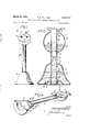
- Figure 1 is an elevation of a toy in accordance with the invention.
- Figure 2 is a vertical central section of one embodiment of the toy.
- Figure 3 is a detail sectional view of the lower reservoir of a toy of the external form shown in Figure 1 when the toy is in the position shown in that figure, this figure as compared with Figure 2 illustrating a modification.
- Figure 4 is a perspective view of one of the two similar half sections of which the toy shown in Figure 3 is composed.
- Figure 5 is a view similar to Figure 3 but showing another modification.
- Figure 6 is a detail horizontal section on the line 6-6 of Figure 5 looking in the direction of the arrows.
- Figure '7 is a view similar to Figures 3 and 5 but showing still another modification.
- Figure 8 is an elevation, partly broken away and showing still another modiflcatiori wherein the toy has a double column arrangement and the columns are provided with transparent win dows separated by opaque zones.
- Figure 9 is a detail horizon al section along the line 9-9 of Figure 8.
- FIGS. 1 and 10 show an embodiment consisting of the essential structural elements of a vertical tubular column I and closed reservoirs 2 and 3 at each end of the column and with which the column is connected in sealed'relation, the reservoirs being mutually spaced to an extent sufficient for the purposes-of the"toy,,that is to say to an extent whereby the column has between them a sufiicient length, e. g., four or five inches.
- the column I may be transparent throughout its extent, or, as shown in Figure 8 and later described in detail, may have spaced transparent portions or windows separated byopaque portions.
- the column and the reservoirs are made of nonbreakable plastic material.
- the reservoirs in each instance provide supporting standards for the toy whereby the toy, standing vertically, is reversible. Therefore, in each instance, the reservoirs may be adapted as to outline and surface ornamentation for an amusing display effect.
- the reservoir 3 is spherical and each face may be painted to present a suitable picture, i. e., the head of a cat as shown in Figure 1.
- the reservoir 3 as of spherical formation, carries a flat faced terminal boss 4 by which the reservoir functions as a supporting standard when the toy is inverted from the position of Figure 1.
- column I extends into and through the chambers provided by the reservoirs, its ends being seated in sealed relation in recesses 5 formed respectively in the base of the reservoir 2 and in the terminal boss 4.
- One of the reservoirs e. g. the reservoir 2
- the portions of the column I which extend into and through the chambers provided by the reservoirs are designated as 8 and in each instance are formed with spaced openings 9 and I0, the openings 9 being in' mean relation and the openings II] in extreme relation.
- These openings in each instance have an areal extent which is a minor fraction of the areal extent of the column in horizontal section, the openings, as liquid flow openings, betweenthe column and the reservoir, therefore, providing for relatively restricted communication etween these partswrz.
- the requirements of the liquid'are that it shall slow gravitational flow of the'liquid through they column are its viscosity and the restricted liquid flow openings between the column. and the reservoirs.
- the liquid is designated A and the air is indicated at B.
- the reservoir 2 is the supporting "ndard.
- These figures assume the operative ion of the toy, that is to say, as shown in Figure 2 they assume a body of liquid A within the upper reservoir 3.
- the liquid flows through the opening 9 (within the reservoir 3) into and through the column I and from the portion of the column I within the chamber provided by the lower reservoir 2 through the opening I0 into this reservoir.
- the liquid As the liquid accumulates in the reservoir 2 it will, of course, displace the air B which will pass in the form of bubbles B through the column I and thence into the reservoir 3 through the opening II], the air occupying the space above .the body of liquid A.
- each web II is provided with terminal webs II, athwart the column and athwart the respective reservoirs, each web I I being in overhanging relation to the particular reservoir in the lower position.
- the web II shown in Figure 3 overhangs the reservoir 2'.
- the webs II are each provided with an opening I2 which is preferably spaced from the wall of the column, the openings I2 interchangeably functionom'ng for the flow of air or liquid accordingly as a web may be in lower or upper relation. The air escapes through the opening I2 of the lower web and flows upwardly in the form of bubbles through the column I.
- Each web II is formed with an inclined wall I3 adjacent and parallel to a portion of the wall of the reservoir.
- the wall I3 in combination with the adjacent portion of the wall of the reservoir provides a passage I4 which at one end is in open communication, as at I5, with the column I and at its opposite end is in open communication, as at I6, withthe reservoir.
- the liquid flows from the uppermost reservoir through the opening I2 and into the column I whence, following the line of least resistance, it flows through the lower passage Ilinto the lower reservoir.
- the air which is displaced by theaccumulation of liquid in the lower reservoir escapes into the column I through the opening I2 and from the column I into the upper reservoir through the upper passage I4.
- the opening I6 through which the liquid escapes from the lower passage I4 into the lower reservoir is suitably below the opening I2 throughiwhich the air escapes from the lower reservoir into the column I.
- liquid flow openings between the column and the reservoirs provide the restricted communication above described, the liquid flow opening I 5 preferably being of less areal extent than the adjacent opening I2.
- the flow of the fluids is similar to that above described in connection vwith the construction shown in Figure .2.
- umn .l is provided with terminal fingers IFI which extend for a suitable distance into the reser-, voirs, the fingers I! being in vertical alinement with the wall of the column I and conforming in cross sectional curvature.
- This modification utilizes the webs H and the openings 12 above described.
- Each web ll is provided with an opening [8 which adjoins the corresponding finger I1 and is preferably of less diameter than the opening I 2.
- the liquid readily flows through the opening 8 and by reason of its wetting quality and capillary attraction fiows along the lower finger ll. Oil has a very pronounced natural wetting quality.
- the liquid be a simple syrup the desired wetting quality can be obtained by an additive in the nature of a synthetic suri-e e ao ion c m o nd r ex mp e, o vl s um sulfosuccinate which is currently sold under the trade name Aerosol O T.
- Aerosol O T The stream of liquid discharges into the lower reservoir from the lower end of the finger l1 and its discharge point is suitably below the corresponding air escape opening Ill.
- the flow of the fluids is similar to that above described in connection with the construction shown in Figure 2.
- each web I I is provided with the openings 12 and I8, as described in connection with Figure 5, the opening l2, as in the embodiment of Figure 5, being suitably spaced from the wall of the column and the opening I B adjoining the wall of the column at the point where the column joins the reservoir.
- the curvature of the wall of the reservoir may, of course, be at any angle relatively to the column I which is suitably less than aright angle, a gentle curvature being preferred.
- the point of discharge of the liquid into the reservoir from the path prescribed by the curved wall portion l9 can be said to be dictated by the plane of the surface level of the accumulated liquid in the reservoir, that is to say the liquid by its wetting quality and capillary attraction can be said to be drawn to that plane which as the accumulation increases progressively moves upward.
- the discharge point of the liquid fiowing along the wall portion l9 into the body of liquid in the lower reservoir is suitably below the opening 52 through which the displaced air escapes from the lower reservoir into the column I.
- each of the four constructions above described may be made in companion longitudinally extending half sections.
- One such half section corresponding to the form shown in Figure 3, is illustrated in Figure 4.
- the companion As made of plastic material the companion :struction previously described.
- the toy includes but a single column
- the toy may. however, have more than one column I.
- This is sufliciently illustrated in Figure 8 wherein the y is p ov ded with two columns (to, each of which corresponds structurally and. functionally to the column I of the -e0I Slruct,ior s previously des ri
- the provisionof more than one eel umn' enables the toy .tobe mad in a var ty of entertaining forms or designs. For example, as
- the columns -la represent the legs and raised arms of a toy figure in the form of a clown, which in the postion shown supports an overhead -r,eceptacle (the upper reservoir) and in the reversed position will appear as performing a hand stand and supporting an overhead receptacle vupon its feet.
- the res rv irs :2 a d :3 are provided in.
- dupl cate one for each column, by means of a separating partition 21!, each reservoir functioning in the same manner as the reservoirs in the con-
- the provision for causing the circulation of the fluids in the manner above describ d may "be f any sui l rm t rm ho n in Fi ure 3 b i g elected fo examp a beir indicated by d tted.
- l ne Figure 8 also shows the columns as having transparent zones or windows lb and intervening opaque zones l c, the opaque zones being provided by the application of suitable paint.
- the construction shown in Figure 8 may be made in matching half sections which are joined together in the manner above explained, their jointure being sufficiently indicated in Figure 9.
- the half sections are provided with inwardly projecting ribs 2! which delimit the interiors of the columns la and also delimit other spaces which are without function but are provided simply for the purpose of lightness of weight.
- a toy of the fluent material operative type consisting of a vertical transparent tubular column and a reservoir connected to the column at each end thereof, the column and the reservoirs constituting a sealed container for immiscible fluids of different specific gravities, the heavier fluid being a liquid which .partially fills the container, each reservoir being formed to provide a supporting standard for the toy and thereby to enable the reversibility of the toy in a vertical position, the reserviors being interchangeably in upper and lower relation accordingly as the toy may be in an initial vertical position or a reversed vertical position, the toy being provided with two openings which establish communication between the column at each end thereof and the reservoir connected to that end, the openings being of restricted areal extent relatively to the areal extent of the column in horizontal section and severally providing for the flow of the liquid from the upper reservoir downwardly through the column and into the lower reservoir and for the escape of the lighter fluid from the lower reservoir upwardly through the column and into the upper reservoir, the toy being formed whereby the liquid which passes from
- the column has terminal webs in which the openings are formed and a wall is arranged in the reservoirs in parallel relation to adjacent portions of the walls of the reservoirs to provide passages,
- the lower passage serving for the flow of the liqu'id from the column into the lower reservoir, the opening for the flow of the liquid from the column being at the upper end of the passage.
Description
March 18, 1952 R w s 25895757 TOY OF THE FLUENT MATERIAL OPERATIVE TYPE Filed Oct. 21, 1950 2 SHEETS-SHEET 1 FJ'QJ.
Zhwentor Pazz/AM/lzdmaj Gttorneg March 18, 1952 P. A. WILLIAMS 2,589,757
TOY OF THE FLUENT MATERIAL OPERATIVE TYPE Filed Oct. 21, 1950 2 SHEETS-SHEET 2 Ihwentor (Ittornen Patented Mar. 18, 1952 UNITED STATES PATENT OFFICE TOY OF THE FLUENT MATERIAL OPERATIVE TYPE Paul A. Williams, Snyder, N. Y.
Application October 21, 1950, Serial No. 191,391
8 Claims. (01. 46-115) This invention relates to an improvement in toys of the fluent material operative type and proposes a novel toy in which provision is made for the flow in countercurrent relation of immiscible fluids of different specific gravities, the heavier fluid being in any case a liquid and the lighter fluid preferably being a gas, e. g. air. The gas will flow upward through the liquid in the form of bubbles and will thereby produce a mystifying visual effect. The flow of the bubbles through the liquid will be at a frequency sufficient for the effect desired, at a relatively constant rate, and through a definite time period sumciently prolonged. It will, of course, be understood that the fluids are sharply differentiated as to color in order that the visual effect may be suitablypronounced.
The invention is characterized by a vertical tubular column which at its ends is connected in sealed relation to reservoirs, one in an upper relation and the other in a lower relation, the column and the reservoirs constituting a sealed container for the fluents and the column being in such communication with each reservoir that the liquid will be discharged into the lower reservoir at a,
point below the point at which the air escapes from the lower reservoir into the column, the air thus escaping passing thence into the upper reservoir and rising through the body of liquid therein which is contemporaneously flowing by gravity from the upper reservoir into and downwardly through the column. Each reservoir is fashioned to serve as a supporting standard for the toy which, as vertically positioned, is reversible in order that a completed cycle of operation may be immediately repeated. preferably opaque whereby to conceal the physical features by which the mystifying effect of the toy is achieved and hence to enhance the effect. The tubular column may be wholly transparent throughout its entire extent or may be transparent at intervals, that is to say, may have transparent zones or windows separated by opaque zones, the transparent and opaque zones conjointly producing a flashing visual effect.
The structural features of the toy are coordinated to the contained liquid. The liquid has a degree of viscosity suitable for the purposes of the invention, that is to say, it will intrinsically have a relatively slow rate of flow and its rate of flow from the upper reservoir into the column and thence into the lower reservoir will be further retarded by the restriction, relatively to the areal horizontal section of the column, of the liquid flow openings or passages between the columnand The reservoirs are the reservoirs. The surface tension of the liquid is such that it will retard the formation of the bubbles of air to a degree whereby the air bubbles. which have a relatively slow rate of flow through the liquid in the column, will be lineally spaced from one another to a suitable extent. The rate of flow of the air bubbles through the column is governed by the viscosity of the liquid and may ideally be three bubbles for every two seconds of time. Of course, the rate of flow of the bubbles may, at choice, be greater or less than the suggested rate in accordance with the selection of the viscosity of the liquid. The amount of liquid is sufiicient to fill either of the reservoirs and the vertical column.
The time of the cycle of flow of the air bubbles is ideally through several minutes, e. g. from three to live minutes. The time selection depends on the rate of flow of the liquid and the relative proportions of the structural parts of the toy. For example, assuming a liquid of a desirable degree of viscosity, a toy having a length of approximately eight inches may have its parts so relatively proportioned that the time for the completion of a cycle of operation will be of the order of five minutes.
In all of the embodiments of the invention the toy is constructed whereby the liquid which passes from the column into the lower reservoir has within the chamber provided by the lower reservoir a downward path of flow which terminates at a point below the opening which provides for the escape of the air from the lower reservoir into the column.
In the accompanying drawings:
Figure 1 is an elevation of a toy in accordance with the invention.
. Figure 2 is a vertical central section of one embodiment of the toy.
Figure 3 is a detail sectional view of the lower reservoir of a toy of the external form shown in Figure 1 when the toy is in the position shown in that figure, this figure as compared with Figure 2 illustrating a modification.
Figure 4 is a perspective view of one of the two similar half sections of which the toy shown in Figure 3 is composed.
Figure 5 is a view similar to Figure 3 but showing another modification.
Figure 6 is a detail horizontal section on the line 6-6 of Figure 5 looking in the direction of the arrows.
Figure '7 is a view similar to Figures 3 and 5 but showing still another modification.
Figure 8 is an elevation, partly broken away and showing still another modiflcatiori wherein the toy has a double column arrangement and the columns are provided with transparent win dows separated by opaque zones.
Figure 9 is a detail horizon al section along the line 9-9 of Figure 8.
Referring to Figures 13nd 2:
These figures show an embodiment consisting of the essential structural elements of a vertical tubular column I and closed reservoirs 2 and 3 at each end of the column and with which the column is connected in sealed'relation, the reservoirs being mutually spaced to an extent sufficient for the purposes-of the"toy,,that is to say to an extent whereby the column has between them a sufiicient length, e. g., four or five inches.
The column I may be transparent throughout its extent, or, as shown in Figure 8 and later described in detail, may have spaced transparent portions or windows separated byopaque portions. The column and the reservoirs are made of nonbreakable plastic material.
The reservoirs in each instance provide supporting standards for the toy whereby the toy, standing vertically, is reversible. Therefore, in each instance, the reservoirs may be adapted as to outline and surface ornamentation for an amusing display effect. For example, in the construction shown in Figure 1 the reservoir 3 is spherical and each face may be painted to present a suitable picture, i. e., the head of a cat as shown in Figure 1.
The reservoir 3, as of spherical formation, carries a flat faced terminal boss 4 by which the reservoir functions as a supporting standard when the toy is inverted from the position of Figure 1.
In the embodiment shown in Figure 2, column I extends into and through the chambers provided by the reservoirs, its ends being seated in sealed relation in recesses 5 formed respectively in the base of the reservoir 2 and in the terminal boss 4.
One of the reservoirs, e. g. the reservoir 2, is
rovided with an opening 6, normally closed by a plug 1, through which the liquid may be introduced into the toy.
The portions of the column I which extend into and through the chambers provided by the reservoirs are designated as 8 and in each instance are formed with spaced openings 9 and I0, the openings 9 being in' mean relation and the openings II] in extreme relation. These openings in each instance have an areal extent which is a minor fraction of the areal extent of the column in horizontal section, the openings, as liquid flow openings, betweenthe column and the reservoir, therefore, providing for relatively restricted communication etween these partswrz.
The requirements of the liquid'are that it shall slow gravitational flow of the'liquid through they column are its viscosity and the restricted liquid flow openings between the column. and the reservoirs.
' In Figure 2 the liquid is designated A and the air is indicated at B. As shown in Figures 1 and2 the reservoir 2 is the supporting "ndard. These figures assume the operative ion of the toy, that is to say, as shown in Figure 2 they assume a body of liquid A within the upper reservoir 3. The liquid flows through the opening 9 (within the reservoir 3) into and through the column I and from the portion of the column I within the chamber provided by the lower reservoir 2 through the opening I0 into this reservoir. As the liquid accumulates in the reservoir 2 it will, of course, displace the air B which will pass in the form of bubbles B through the column I and thence into the reservoir 3 through the opening II], the air occupying the space above .the body of liquid A.
With the toy" positioned as shown in Figure 2, the flow of the fluids A and B as above described will be continued for a period of several minutes and will cease when the liquid A is drained from the reservoir 3 and. the air is displaced from the reservoir 2. During the flow of the liquid A from the reservoir 3 through the column I and into the reservoir 2, the bubbles B will pass upwardly through the column I at a comparatively slow rate of flow as above explained.
When the cycle of flow of the fluids with the toy in the position shown in Figures 1 and 2 has been completed as above explained, the toy is inverted and the cycle of flow of the liquids is repeated.
Various modifications may be provided to cause the flow of the fluids in the manner above described. Three modifications are shown in Figures 3, 5 and '7 respectively.
In the construction shown in Figure 3 the column I does not extend into the reservoirs. In-
.stead, at its points of connection to the reservoirs .2 and 3 it is provided with terminal webs II, athwart the column and athwart the respective reservoirs, each web I I being in overhanging relation to the particular reservoir in the lower position. The web II shown in Figure 3 overhangs the reservoir 2'. The webs II are each provided with an opening I2 which is preferably spaced from the wall of the column, the openings I2 interchangeably functiom'ng for the flow of air or liquid accordingly as a web may be in lower or upper relation. The air escapes through the opening I2 of the lower web and flows upwardly in the form of bubbles through the column I. Each web II is formed with an inclined wall I3 adjacent and parallel to a portion of the wall of the reservoir. The wall I3 in combination with the adjacent portion of the wall of the reservoir provides a passage I4 which at one end is in open communication, as at I5, with the column I and at its opposite end is in open communication, as at I6, withthe reservoir. The liquid flows from the uppermost reservoir through the opening I2 and into the column I whence, following the line of least resistance, it flows through the lower passage Ilinto the lower reservoir. The air which is displaced by theaccumulation of liquid in the lower reservoir escapes into the column I through the opening I2 and from the column I into the upper reservoir through the upper passage I4. The opening I6 through which the liquid escapes from the lower passage I4 into the lower reservoir is suitably below the opening I2 throughiwhich the air escapes from the lower reservoir into the column I. The liquid flow openings between the column and the reservoirs provide the restricted communication above described, the liquid flow opening I 5 preferably being of less areal extent than the adjacent opening I2. The flow of the fluids is similar to that above described in connection vwith the construction shown in Figure .2.
umn .l is provided with terminal fingers IFI which extend for a suitable distance into the reser-, voirs, the fingers I! being in vertical alinement with the wall of the column I and conforming in cross sectional curvature. This modification utilizes the webs H and the openings 12 above described. Each web ll, however, is provided with an opening [8 which adjoins the corresponding finger I1 and is preferably of less diameter than the opening I 2. The liquid readily flows through the opening 8 and by reason of its wetting quality and capillary attraction fiows along the lower finger ll. Oil has a very pronounced natural wetting quality. If the liquid be a simple syrup the desired wetting quality can be obtained by an additive in the nature of a synthetic suri-e e ao ion c m o nd r ex mp e, o vl s um sulfosuccinate which is currently sold under the trade name Aerosol O T. The stream of liquid discharges into the lower reservoir from the lower end of the finger l1 and its discharge point is suitably below the corresponding air escape opening Ill. The flow of the fluids is similar to that above described in connection with the construction shown in Figure 2.
In the modification shown in Figure 7 the wall of each reservoir has a gentle curve, as shown at l9, adjacent the corresponding end' of the column I, the combined curvature of the adjacent parts of the walls of the column I and the reservoir being generally of ogee outline. In this modification each web I I is provided with the openings 12 and I8, as described in connection with Figure 5, the opening l2, as in the embodiment of Figure 5, being suitably spaced from the wall of the column and the opening I B adjoining the wall of the column at the point where the column joins the reservoir. The finger I! of the construction shown in Figure is dispensed with and the curved portion IQ of the wall of each reservoir is relied upon to prescribe the path of flow of the liquid from the column into the lower reservoir, the liquid as it flows through the opening l8 flowing along the curved wall portion I9 of the reservoir by reason of its wetting quality and capillary attraction. The curvature of the wall of the reservoir may, of course, be at any angle relatively to the column I which is suitably less than aright angle, a gentle curvature being preferred. In this modification the point of discharge of the liquid into the reservoir from the path prescribed by the curved wall portion l9 can be said to be dictated by the plane of the surface level of the accumulated liquid in the reservoir, that is to say the liquid by its wetting quality and capillary attraction can be said to be drawn to that plane which as the accumulation increases progressively moves upward. Thereby, in any event, the discharge point of the liquid fiowing along the wall portion l9 into the body of liquid in the lower reservoir is suitably below the opening 52 through which the displaced air escapes from the lower reservoir into the column I.
From a manufacturing standpoint each of the four constructions above described may be made in companion longitudinally extending half sections. One such half section, corresponding to the form shown in Figure 3, is illustrated in Figure 4. As made of plastic material the companion :struction previously described.
ra tice, are iimpregnatedwitn .a solution w ic when the half sections are fitted together :in matching relation, constitutes in efiect a permanent sealing'weld between them.
In the .four forms above described the toy includes but a single column The toy may. however, have more than one column I. This is sufliciently illustrated in Figure 8 wherein the y is p ov ded with two columns (to, each of which corresponds structurally and. functionally to the column I of the -e0I Slruct,ior s previously des ri The provisionof more than one eel umn' enables the toy .tobe mad in a var ty of entertaining forms or designs. For example, as
shown in Figure 8, the columns -la represent the legs and raised arms of a toy figure in the form of a clown, which in the postion shown supports an overhead -r,eceptacle (the upper reservoir) and in the reversed position will appear as performing a hand stand and supporting an overhead receptacle vupon its feet.- With two column the res rv irs :2 a d :3 are provided in. dupl cate, one for each column, by means of a separating partition 21!, each reservoir functioning in the same manner as the reservoirs in the con- The provision for causing the circulation of the fluids in the manner above describ d may "be f any sui l rm t rm ho n in Fi ure 3 b i g elected fo examp a beir indicated by d tted. l ne Figure 8 also shows the columns as having transparent zones or windows lb and intervening opaque zones l c, the opaque zones being provided by the application of suitable paint.
As a manufacturing proposition the construction shown in Figure 8 may be made in matching half sections which are joined together in the manner above explained, their jointure being sufficiently indicated in Figure 9. The half sections are provided with inwardly projecting ribs 2! which delimit the interiors of the columns la and also delimit other spaces which are without function but are provided simply for the purpose of lightness of weight.
I claim:
1. A toy of the fluent material operative type consisting of a vertical transparent tubular column and a reservoir connected to the column at each end thereof, the column and the reservoirs constituting a sealed container for immiscible fluids of different specific gravities, the heavier fluid being a liquid which .partially fills the container, each reservoir being formed to provide a supporting standard for the toy and thereby to enable the reversibility of the toy in a vertical position, the reserviors being interchangeably in upper and lower relation accordingly as the toy may be in an initial vertical position or a reversed vertical position, the toy being provided with two openings which establish communication between the column at each end thereof and the reservoir connected to that end, the openings being of restricted areal extent relatively to the areal extent of the column in horizontal section and severally providing for the flow of the liquid from the upper reservoir downwardly through the column and into the lower reservoir and for the escape of the lighter fluid from the lower reservoir upwardly through the column and into the upper reservoir, the toy being formed whereby the liquid which passes from the column into the lower reservoir through the opening provided for such passage has within the chamber provided by the lower reservoir a downward'p ath of flow which terminates at a point" below the opening which provides for the escape of the lighter fluid from the lower reservoir into the column.
2. A toy as set forth in claim 1 wherein the liquid has a selected degree of viscosity and .a pronounced wetting action and the lighter fluid 15 air.
3. A toy as set forth in claim 1 wherein the walls of the reservoirs are opaque.
4. A toy as set forth in claim 1 wherein the column extends through the reservoirs and has a sealed connection with the reservoirs, the portions 'of the column within the reservoirs being provided with the openings which severally function for the flow of the liquid and the lighter 5. A toy as set forth in claim 1 wherein the column has terminal webs in which the openings are formed and a wall is arranged in the reservoirs in parallel relation to adjacent portions of the walls of the reservoirs to provide passages,
the lower passage serving for the flow of the liqu'id from the column into the lower reservoir, the opening for the flow of the liquid from the column being at the upper end of the passage.
'6. A toy as set forth in claim 1 wherein the column has terminal webs in which the openings are formed, a finger projects from the column into each reservoir, and the opening which provides for the passage of the liquid from the column into the lower "reservoir adjoins the finger, the latter prescribing a path of flow for the liquid from the column into the lower reservoir.
V 7. A toy as set forth in claim 1 wherein the column has terminal webs in which the openings are formed, the wall of each reservoir has a .gentle curve adjacent the corresponding end of REFERENCES CITED The following references are of record in the file of this patent:
UNITED STATES PATENTS Number Name Date 673,022 Iski et a1. Apr. 30, 1901 2,144,857 Schultz Jan. 24, 1939 2,515,171 Abel July 18, 1950
Priority Applications (1)
| Application Number | Priority Date | Filing Date | Title |
|---|---|---|---|
| US191391A US2589757A (en) | 1950-10-21 | 1950-10-21 | Toy of the fluent material operative type |
Applications Claiming Priority (1)
| Application Number | Priority Date | Filing Date | Title |
|---|---|---|---|
| US191391A US2589757A (en) | 1950-10-21 | 1950-10-21 | Toy of the fluent material operative type |
Publications (1)
| Publication Number | Publication Date |
|---|---|
| US2589757A true US2589757A (en) | 1952-03-18 |
Family
ID=22705300
Family Applications (1)
| Application Number | Title | Priority Date | Filing Date |
|---|---|---|---|
| US191391A Expired - Lifetime US2589757A (en) | 1950-10-21 | 1950-10-21 | Toy of the fluent material operative type |
Country Status (1)
| Country | Link |
|---|---|
| US (1) | US2589757A (en) |
Cited By (19)
| Publication number | Priority date | Publication date | Assignee | Title |
|---|---|---|---|---|
| US2752725A (en) * | 1952-10-28 | 1956-07-03 | Kentworth Corp | Fluid filled container with movable objects therein |
| US2871617A (en) * | 1956-03-05 | 1959-02-03 | John F West | Toy |
| US3246892A (en) * | 1962-03-16 | 1966-04-19 | Blazon Inc | Slide spray device |
| US3706149A (en) * | 1970-09-29 | 1972-12-19 | George Olivieri | Display device |
| US3738036A (en) * | 1971-02-19 | 1973-06-12 | Mattel Inc | Globule display toy |
| US4006902A (en) * | 1974-08-08 | 1977-02-08 | Dynavision Corporation | Amusement device with a bubble movable in a liquid having means for controlling the size and movement of the bubble |
| US4257185A (en) * | 1979-04-05 | 1981-03-24 | Tomson Steven H | Bubble producing, preserving and display apparatus |
| US4258912A (en) * | 1980-01-21 | 1981-03-31 | Reighart Ii Ray R | Tornado novelty device |
| US5258209A (en) * | 1990-09-12 | 1993-11-02 | Franklin Mint Company | Decorative bell |
| US5292564A (en) * | 1992-03-11 | 1994-03-08 | Lee Vincent K W | Fluid-contained display ornament |
| US5476406A (en) * | 1994-12-30 | 1995-12-19 | Cheng; W.-Z. | Decorative floating toy |
| US5921841A (en) * | 1997-07-28 | 1999-07-13 | Coleman; Thomas J. | Swirlee pop |
| USD420306S (en) * | 1999-02-08 | 2000-02-08 | Sands Jeremy J | Bubble generating device |
| USD420307S (en) * | 1999-04-23 | 2000-02-08 | Sands Jeremy J | Wall mounted bubble generating device |
| USD421237S (en) * | 1999-04-29 | 2000-02-29 | Sands Jeremy J | Freestanding bubble generating display device |
| US6312311B1 (en) * | 1999-02-12 | 2001-11-06 | Learning Curve International, Inc. | Water tower assembly with variable water level |
| US20020174577A1 (en) * | 2001-03-14 | 2002-11-28 | Massachusetts Institute Of Technology | Visual display device |
| US6582274B1 (en) * | 2000-04-26 | 2003-06-24 | Basic Fun, Inc. | Noise making toy |
| USD833537S1 (en) * | 2016-10-21 | 2018-11-13 | Marcia L. Haut | Infant rattle |
Citations (3)
| Publication number | Priority date | Publication date | Assignee | Title |
|---|---|---|---|---|
| US673022A (en) * | 1900-05-15 | 1901-04-30 | Frederick A Biehl | Intermittent thermotic motor. |
| US2144857A (en) * | 1936-03-31 | 1939-01-24 | Schultz Hermann | Sandglass |
| US2515171A (en) * | 1946-05-20 | 1950-07-18 | Abel Mona Cordell | Transparent hollow toy ball |
-
1950
- 1950-10-21 US US191391A patent/US2589757A/en not_active Expired - Lifetime
Patent Citations (3)
| Publication number | Priority date | Publication date | Assignee | Title |
|---|---|---|---|---|
| US673022A (en) * | 1900-05-15 | 1901-04-30 | Frederick A Biehl | Intermittent thermotic motor. |
| US2144857A (en) * | 1936-03-31 | 1939-01-24 | Schultz Hermann | Sandglass |
| US2515171A (en) * | 1946-05-20 | 1950-07-18 | Abel Mona Cordell | Transparent hollow toy ball |
Cited By (20)
| Publication number | Priority date | Publication date | Assignee | Title |
|---|---|---|---|---|
| US2752725A (en) * | 1952-10-28 | 1956-07-03 | Kentworth Corp | Fluid filled container with movable objects therein |
| US2871617A (en) * | 1956-03-05 | 1959-02-03 | John F West | Toy |
| US3246892A (en) * | 1962-03-16 | 1966-04-19 | Blazon Inc | Slide spray device |
| US3706149A (en) * | 1970-09-29 | 1972-12-19 | George Olivieri | Display device |
| US3738036A (en) * | 1971-02-19 | 1973-06-12 | Mattel Inc | Globule display toy |
| US4006902A (en) * | 1974-08-08 | 1977-02-08 | Dynavision Corporation | Amusement device with a bubble movable in a liquid having means for controlling the size and movement of the bubble |
| US4257185A (en) * | 1979-04-05 | 1981-03-24 | Tomson Steven H | Bubble producing, preserving and display apparatus |
| US4258912A (en) * | 1980-01-21 | 1981-03-31 | Reighart Ii Ray R | Tornado novelty device |
| US5258209A (en) * | 1990-09-12 | 1993-11-02 | Franklin Mint Company | Decorative bell |
| US5292564A (en) * | 1992-03-11 | 1994-03-08 | Lee Vincent K W | Fluid-contained display ornament |
| US5476406A (en) * | 1994-12-30 | 1995-12-19 | Cheng; W.-Z. | Decorative floating toy |
| US5921841A (en) * | 1997-07-28 | 1999-07-13 | Coleman; Thomas J. | Swirlee pop |
| USD420306S (en) * | 1999-02-08 | 2000-02-08 | Sands Jeremy J | Bubble generating device |
| US6312311B1 (en) * | 1999-02-12 | 2001-11-06 | Learning Curve International, Inc. | Water tower assembly with variable water level |
| USD420307S (en) * | 1999-04-23 | 2000-02-08 | Sands Jeremy J | Wall mounted bubble generating device |
| USD421237S (en) * | 1999-04-29 | 2000-02-29 | Sands Jeremy J | Freestanding bubble generating display device |
| US6582274B1 (en) * | 2000-04-26 | 2003-06-24 | Basic Fun, Inc. | Noise making toy |
| US20020174577A1 (en) * | 2001-03-14 | 2002-11-28 | Massachusetts Institute Of Technology | Visual display device |
| US6681508B2 (en) | 2001-03-14 | 2004-01-27 | Massachusetts Institute Of Technology | Visual display device |
| USD833537S1 (en) * | 2016-10-21 | 2018-11-13 | Marcia L. Haut | Infant rattle |
Similar Documents
| Publication | Publication Date | Title |
|---|---|---|
| US2589757A (en) | Toy of the fluent material operative type | |
| US2752725A (en) | Fluid filled container with movable objects therein | |
| US3071888A (en) | Bubbling amusement devices | |
| US4034493A (en) | Fluid novelty device | |
| US1810453A (en) | Chewing gum confection | |
| US3738036A (en) | Globule display toy | |
| US3413230A (en) | Floating soap cake with included educational features | |
| US5749799A (en) | Lava-producing playball | |
| US2542100A (en) | Combined bubble pipe and tethered ball | |
| US5921841A (en) | Swirlee pop | |
| US2157763A (en) | Doll | |
| US2540502A (en) | Liquid timer | |
| US1550057A (en) | Combined soap-bubble device and humidifier | |
| US3245174A (en) | Toy nursing bottle for dolls | |
| US344515A (en) | Loeenz biehl | |
| US1419509A (en) | Bottle | |
| US3438197A (en) | Ornamental timers | |
| US3070921A (en) | Tearing mechanism for weeping doll | |
| US3874589A (en) | Self-acting waterspout device | |
| US5528561A (en) | Color changing hourglass assembly | |
| US4257185A (en) | Bubble producing, preserving and display apparatus | |
| US1648344A (en) | Article of manufacture | |
| US6270420B1 (en) | Ornamental liquid container producing dynamic views | |
| DE451887C (en) | Body of puzzles | |
| US2763142A (en) | Visual display drinking vessel |