US2599208A - Illuminated toy vehicle - Google Patents
Illuminated toy vehicle Download PDFInfo
- Publication number
- US2599208A US2599208A US77572A US7757249A US2599208A US 2599208 A US2599208 A US 2599208A US 77572 A US77572 A US 77572A US 7757249 A US7757249 A US 7757249A US 2599208 A US2599208 A US 2599208A
- Authority
- US
- United States
- Prior art keywords
- toy
- cell
- dry
- pull
- base plate
- Prior art date
- Legal status (The legal status is an assumption and is not a legal conclusion. Google has not performed a legal analysis and makes no representation as to the accuracy of the status listed.)
- Expired - Lifetime
Links
- 239000002184 metal Substances 0.000 description 6
- 230000004048 modification Effects 0.000 description 4
- 238000012986 modification Methods 0.000 description 4
- 238000010276 construction Methods 0.000 description 3
- 208000027534 Emotional disease Diseases 0.000 description 2
- 238000004873 anchoring Methods 0.000 description 2
- 230000002045 lasting effect Effects 0.000 description 2
- 238000004519 manufacturing process Methods 0.000 description 2
- OQCFWECOQNPQCG-UHFFFAOYSA-N 1,3,4,8-tetrahydropyrimido[4,5-c]oxazin-7-one Chemical compound C1CONC2=C1C=NC(=O)N2 OQCFWECOQNPQCG-UHFFFAOYSA-N 0.000 description 1
- 101100285518 Drosophila melanogaster how gene Proteins 0.000 description 1
- 241000195644 Neochloris Species 0.000 description 1
- 229910000639 Spring steel Inorganic materials 0.000 description 1
- FZNCGRZWXLXZSZ-CIQUZCHMSA-N Voglibose Chemical compound OCC(CO)N[C@H]1C[C@](O)(CO)[C@@H](O)[C@H](O)[C@H]1O FZNCGRZWXLXZSZ-CIQUZCHMSA-N 0.000 description 1
- 239000003086 colorant Substances 0.000 description 1
- 239000000463 material Substances 0.000 description 1
- 229910001092 metal group alloy Inorganic materials 0.000 description 1
- 239000000123 paper Substances 0.000 description 1
- 239000011120 plywood Substances 0.000 description 1
Images
Classifications
-
- A—HUMAN NECESSITIES
- A63—SPORTS; GAMES; AMUSEMENTS
- A63H—TOYS, e.g. TOPS, DOLLS, HOOPS OR BUILDING BLOCKS
- A63H17/00—Toy vehicles, e.g. with self-drive; ; Cranes, winches or the like; Accessories therefor
- A63H17/26—Details; Accessories
- A63H17/28—Electric lighting systems
Definitions
- the present invention relates to a childs toy and, more particularly, it relates to an electri-' cally illuminated toy of the type which may be pulled along the fioor by means of a pull cord.
- Another object of the invention is to provide a newand improved childs pull toy embodying a novel electric dry-cell lighting circuit as an illuminating source within the toy.
- a further object of the invention is to provide a new and improved electrically illuminated childs pull toy which will become illuminated only when the toy is being pulled along a surface by its pull cord.
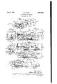
- Fig. 1 is a perspective view of the toy, showing its outward appearance
- Fig. 2 is a longitudinal elevational view partly broken away to show the interior of the toy, particularly the dry-cell lighting unit forming a part of the invention
- Fig. 3 is a front sectional view taken along the plane 3-3 of Fig. 2;
- Fig. 4 is a top plan view of the dry-cell lighting unit within the body of the toy;
- Fig. 5 is an enlarged side plan view of a portion of the dry-cell lighting unit to more clearly illustrate the spring-switch contacting means for completing the electric circuit;
- Fig. 6 is a longitudinal elevational view similar to that of Fig. 5 but showing certain modifications in the construction of the dry cell lighting unit structure.
- Fig. 7 is illustrative of the manner in which the dry-cell lighting unit of Fig. 2 is adaptable to a toy automobile.
- a childs pull toy comprising a hollow rectangular body I0 having its forward bottom edge rounded or sledded and having a pull cord 12 extending from a grommeted aperture I4 centrally located in the forward end of the body, said pull cord being secured within the body of the toy as will be hereafter more fully described.
- the body of the toy may be constructed of cardboard, plywood, plastic, sheet metal or any other suitable material which is impervious to light.
- the top, ends and sides of the toy body are provided with the openings of Figures 16, 18 and 20.
- These openings may take any'approved 2 design, such as stars, hearts, crescents, or the outline of airplanes, ships and thelike. The possibilities in this respect are unlimited. Varicolored configurations of openings are attained by lining the openings on the inside of the toy with transparent paper, film or the like of suitable colors as indicated at 2 I.
- the body to has a lid 22 hinged to the front end portion 24 such that it may be lifted to provide access to the interior of the body.
- the hinged top 22 In its closed position, the hinged top 22 is secured by a snap hook or other suitable fastener 25 between the top and the back end of the body.
- the lighting unit comprises essentially a metal base plate 30; forward, intermediate and rearwardly disposed dry-cell holding and contacting means 32, 34 and 36; a forwardly disposed flexible switch or contacting blade 38, an electric light bulb 40 and an electric dry-cell 42.
- a pull cord I2 is seen as passing through the aperture I4 from the outside of the toy body to the interior thereof, leading around and through an eye 44 and having its end secured to the top of the switch blade 38 at 31.
- the base plate 30 is provided with forwardly and rearwardly located tangs 33 as a means for positively securing the base plat to the bottom of the interior of the toy body in the manner illustrated.
- the base plate 30 is further provided with centrally located clips 34 and 35 positioned to receive and hold the dry-cell 42 in a fixed position on the base plate 30.
- Figs. 2, 3 and 4 show a simple and effective structure wherein a rearwardly holding and contacting blade 36 has been stamped out of the sheet metal of the base plate and bent upwards thereto in the manner shown.
- the two forward stub fingers 32, 32 have been stamped out of the sheet metal of the base plate and bent upwardly at right angles thereto to provide forward abutments, the distance between the holding stubs 32, 32 and the rear contacting blade 36 being such as to closely accommodate the dry-cell 42; positive longitudinal holding of the dry-cell against the forward abutment stubs 32, 32 being effected by the spring clip action of the rear contacting blade 36 which is seen to project upwardly from the base plate 30 and in contact with the rear 3 transverse vertical terminal surface of the drycell.
- Transverse positioning and anchoring of the dry-cell 42 with respect to the base plate is accomplished by the intermediate metal clips 34 and 35. As shown in the drawing, these clips are arced to conform with the perimeter of the cylindrical dry-cell 42.
- the left-hand clip 34 is arced upwardly a. distance such as to terminate at a point on .top ofz the dry-cell above the longitudi nal axis and" is provided with a verticallyand transversely disposed eye 44 at its upper end.
- the left-hand clip likewise extends up.-
- the bulb is of the -standard; flash ightyp l u tra ed. hen; the. bu
- the rear holdingbladet36, the forward switch blade 38, the bulb socket 46 and the bulb 40 constitute a simple lighting circuit for the lighting otthebulb MLwhen its center terminal is brought into electrical contact with the center positive terminal v of; the dry-cell.
- the spring switch blade 38 it is important to the proper'function of the spring switch blade 38 that it be magle of spring steel or other conducting metal alloy having suff cient elasticity that the blade twillnot become permanentlvdistorted, but willalw s r turn m h mal ysriicaland Ql i of; contactpos ion with respect. to. the.
- the base P a here is i id. u b-ba din rac et. i2v h ving, a o t. 46. or; r c ivin he i'shthulh P hat-the cen er.- t m al, o the irr ell.
- nu l cord will distort. org'flex the switch bIQQBQFIA; contact with the rear surface of the. drv-celh he e y ompletin the e t r i itand z cau ingthehghtbum 411. toh m V Rel sin he. en SiQB Q11 he 12 1 r h s n actio Q j hs switch; blade, 54 w l au e; tt e u n c ts no mal r ara lel. a d.
- the bulb holding bracket 52 is rigid and the circuit closing means is the switch blade 54 to the rear of the dry-cell and is distorted into contact therewith by a direct pull on the pull cord.
- Fig. 7 of the drawing illustrates the manner in which the lighting unit of Figs. 2, 3 and 4 may be adapted for use in other types of childrens pull toys, such as toy automobiles, airplanes, boats, etc., to illuminate such toys and whereby the electric illuminating means will function automatically when the toy is pulled by means of a pull cord.
- the openings in the body of the toy are limited to two circular light emitting apertures 56 in the front of the toy to simulate automobile head lights when the toy is being pulled.
- the present invention is directed toward a new and novel toy particularly suitable for young children between the ages of one and five years, the novelty of which resides in the fact that the invention provides a mechanically simple means whereby inexpensive childrens pull toys of the types described are electrically illuminated by a dry-cell light circuit and wherein such lighting is entirely and automatically controlled by the child and made operative when the toy is being pulled along the floor or other surface and wherein the lighting circuit will be automatically rendered non-operative when the toy is not being pulled, thereby assuring maximum life to the dry-cell of the lighting circuit.
- the novelty of having a toy which lights up only when the toy is being pulled is instructive and of lasting curiosity and pleasure from the standpoint of a child.
- the present invention has another desirable advantage in that it may be manufactured and sold at a very low cost, a most important consideration in the commerical marketing of any childs toy.
- a toy automobile comprising a hollow body, wheels attached to said body to support the same upon a surface, a headlight lamp for said automobile and a battery cell mounted inside of said hollow body, and means for closing a circuit between said lamp and cell, said means including a cord by which said toy may be pulled, a resilient switch member supporting said lamp in said body, said cord attached to said switch member and extending outwardly from said body through an opening therein whereby when the end of said cord is pulled said switch member will be flexed to close said circuit to light said headlight lamp.
Description
June 3, 1952 A. D. STARR 2,599,203
ILLUMINATED TOY VEHICLE Filed Feb. 21, 1949 wow? 1 14% Patented June 3, 1952 UNITED STATES PATENT O'FFICE.
ILLUMINATED TOY VEHICLE Allan n. Starr, Carlinville, 111. Application February 21, 1949, Serial No. 77,572 7 l- Clain'i.
The present invention relates to a childs toy and, more particularly, it relates to an electri-' cally illuminated toy of the type which may be pulled along the fioor by means of a pull cord.
It is the primary object of the invention to provide a durable and inexpensive toy suitable for children between the ages of one and five years embodying lasting attraction and fascination.
Another object of the invention is to provide a newand improved childs pull toy embodying a novel electric dry-cell lighting circuit as an illuminating source within the toy.
A further object of the invention is to provide a new and improved electrically illuminated childs pull toy which will become illuminated only when the toy is being pulled along a surface by its pull cord.
Other objects of the invention will appear from the following description taken in connection with the drawing, in which:
Fig. 1 is a perspective view of the toy, showing its outward appearance;
Fig. 2 is a longitudinal elevational view partly broken away to show the interior of the toy, particularly the dry-cell lighting unit forming a part of the invention;
Fig. 3 is a front sectional view taken along the plane 3-3 of Fig. 2;
Fig. 4 is a top plan view of the dry-cell lighting unit within the body of the toy;
Fig. 5 is an enlarged side plan view of a portion of the dry-cell lighting unit to more clearly illustrate the spring-switch contacting means for completing the electric circuit;
Fig. 6 is a longitudinal elevational view similar to that of Fig. 5 but showing certain modifications in the construction of the dry cell lighting unit structure; and
Fig. 7 is illustrative of the manner in which the dry-cell lighting unit of Fig. 2 is adaptable to a toy automobile.
' With reference to Fig. l of the drawing, there is shown a childs pull toy comprising a hollow rectangular body I0 having its forward bottom edge rounded or sledded and having a pull cord 12 extending from a grommeted aperture I4 centrally located in the forward end of the body, said pull cord being secured within the body of the toy as will be hereafter more fully described.
The body of the toy may be constructed of cardboard, plywood, plastic, sheet metal or any other suitable material which is impervious to light. The top, ends and sides of the toy body are provided with the openings of Figures 16, 18 and 20. These openings may take any'approved 2 design, such as stars, hearts, crescents, or the outline of airplanes, ships and thelike. The possibilities in this respect are unlimited. Varicolored configurations of openings are attained by lining the openings on the inside of the toy with transparent paper, film or the like of suitable colors as indicated at 2 I.
The body to has a lid 22 hinged to the front end portion 24 such that it may be lifted to provide access to the interior of the body. In its closed position, the hinged top 22 is secured by a snap hook or other suitable fastener 25 between the top and the back end of the body.
Referring now to Figs. 2, 3, 4 and 5 of the drawing, there are shown various views of the novel dry-cell lighting unit embodied by and forming a part of the present invention. The lighting unit comprises essentially a metal base plate 30; forward, intermediate and rearwardly disposed dry-cell holding and contacting means 32, 34 and 36; a forwardly disposed flexible switch or contacting blade 38, an electric light bulb 40 and an electric dry-cell 42. A pull cord I2 is seen as passing through the aperture I4 from the outside of the toy body to the interior thereof, leading around and through an eye 44 and having its end secured to the top of the switch blade 38 at 31.
The base plate 30 is provided with forwardly and rearwardly located tangs 33 as a means for positively securing the base plat to the bottom of the interior of the toy body in the manner illustrated.
The base plate 30 is further provided with centrally located clips 34 and 35 positioned to receive and hold the dry-cell 42 in a fixed position on the base plate 30.. While the manner in which the dry-cell is secured to the base plate is merely a matter of detail in construction, Figs. 2, 3 and 4 show a simple and effective structure wherein a rearwardly holding and contacting blade 36 has been stamped out of the sheet metal of the base plate and bent upwards thereto in the manner shown. Likewise, the two forward stub fingers 32, 32 have been stamped out of the sheet metal of the base plate and bent upwardly at right angles thereto to provide forward abutments, the distance between the holding stubs 32, 32 and the rear contacting blade 36 being such as to closely accommodate the dry-cell 42; positive longitudinal holding of the dry-cell against the forward abutment stubs 32, 32 being effected by the spring clip action of the rear contacting blade 36 which is seen to project upwardly from the base plate 30 and in contact with the rear 3 transverse vertical terminal surface of the drycell.
Transverse positioning and anchoring of the dry-cell 42 with respect to the base plate is accomplished by the intermediate metal clips 34 and 35. As shown in the drawing, these clips are arced to conform with the perimeter of the cylindrical dry-cell 42. The left-hand clip 34 is arced upwardly a. distance such as to terminate at a point on .top ofz the dry-cell above the longitudi nal axis and" is provided with a verticallyand transversely disposed eye 44 at its upper end.
The left-hand clip likewise extends up.-
Wardly from the base plate following the pa -P riphery of the dry-cell cylindrical surface but only to a point slightly above the projectedlongia.
tudinal axis of said dry-cell, cylinder, whereby there is an adequate distance between the ends of the right and left-hand clips to permit in:- sertion and removal of the;dry-cel1.
While- I; have il ustrated. nd es ibed a. 21 7 ferrsctmeanstonnosibioninsandlholdinsq he-drr cell-ton the..-basen a e; t shsmld er s ze hat atvarietr herne h ps qua 1x ui able m ans may-beemplored: and tisncit nte de hat h Dn sen....1nv nt 0 -hs mi d l o he; stru tu e n means illustrated. For; instance, other-standard; sizesandishanes ec ric; rr- 1s2masi e i which; would; ne ssi a e: m dific tiqnsi n: he anchoring.- s ru tu e, n; hi onnection, t. i mintediout that. all-par d the pr s ntt v ns ticn;partict larlr her ishw -unit truq urerhe sl been designed; to. end: hemse ves o im ici y and; economyn manufacture and; it 2 1m nlateslz hatzthehas mate:mills: tans 3.
firmaw esta n s za tionfmm sheetmetakma furthe e erence 11 particularlyomes. 2 3;. nd: 5 her of ne of. thef etureszofthe resent nv n ion he fiexi: le spr switchinsi b ade cen re. d seas d: forward 0f.- he d r e tez and e e d s@ a.wardlit-fromthezbase te; uh a t t:- e ica e eot-and hav n szlatg ali ur ceat right ang e 1, i
with. on t d nal ax s; f. the r-s l i spr ngtime-hasa o om;fia ser r niwl i h is riveted, welded or otherwise positively attached. tQ=' he..bassin af 0;-. h wi ch ade-3i= s-r; vided; with SQIYQWI sock t- 6 n r-m basen iatez nd ts; peroda e te. slinsh; queh the; blade. for rece v n t e screw h ll; e minal. of alight bulb 40. The bulb is of the -standard; flash ightyp l u tra ed. hen; the. bu
alo ith e b h wil nm r t thmus t ba k. s de: Q the; sw c de-1 s c -bl e s. s. fnntheepmvidediat;mangerendlwithla ma l re it. icatesletfil.
To; make: he; toy ne ativel n nd. f the-12. 1; comm-is: attach dame ns t. ndaq t e- 'tch blade: 38:; at. 31am; e ack: hli r eh; hev trans-e verse eyeM. and; hen: or rd ush he sham me d-apertur W 111 119 qnh n f: the 9% bodyto t e. ex erior tb i Q.f:- Them- 9rd: .21 mar-be ofsanr ui a-h e en th. t acil tat the; miningof: the my bitwhi s- In1Fis- 2; the: n l. co s; sh a e n rmallyslack. unde w ich nd ion he; Switchb ad 3. will be norma lypara l l th the mard ac t of the dry-cell fi2 a nd spaced. therefrom; to holdtl e'cen ter terminal: of the bells: 4.8; qnt f. contact with the center positive terrmnal of th .d .11 cell.
As illustrated in, Fig. 4; when a forward pull is ia sthe t applied to the external free end of the pull cord, the cord will become taut and the pull transferred through the cord to the switch blade 38 which will be flexed or distorted to bring the center terminal of the bulb 4|] into contact with the center terminal of the dry-cell, whereby the light circuit will be completed and the toy body thereafter motivated along a surface in the direction of pull.
As can be understood from the foregoing desoriptionofrtheassociatiqn qf thq base plate 30, the rear holdingbladet36, the forward switch blade 38, the bulb socket 46 and the bulb 40, constitute a simple lighting circuit for the lighting otthebulb MLwhen its center terminal is brought into electrical contact with the center positive terminal v of; the dry-cell. As will be hereafter more clearly pointed out, it is important to the proper'function of the spring switch blade 38 that it be magle of spring steel or other conducting metal alloy having suff cient elasticity that the blade twillnot become permanentlvdistorted, but willalw s r turn m h mal ysriicaland Ql i of; contactpos ion with respect. to. the. dry-cell; when.tension on the .pull cord IZ is released' Fig, 5,. f; he, aw cl ar l ustrates, the, switch h r es mc ure n. tslncrm l n dist r e g g ir q l l hw b ur he eQsniz@d het. p oper. un tion o thelightins un tre res het aw esi t n the exible witc 'ps blade. 38 .b e. slightly less. than the. frictional resistanse l h W.- t aiI SRIQ WQI'Q -PHH alon a. surface, such thatwhena pull is applied' tothe Qord [2, the immedi t efiectwillbe the actuatnex fi i l h l lifi qlose he ight n irciiit,v llcwi s hich he or. w l. b -{ms ivated in. theldir ection o-fpulL Fig. 6 of the drawing illustrates a sirnplnjed modification in. thelighting unit str rcturewheremine r s i mn v selvhe din'lpla sli nfibs. base plate by an upwalidly-open. metal. Q-shaped; p in c1 12 we e r herw se mcun ed f the base plate. At the forward. end or; the base P a here is i id. u b-ba din rac et. i2v h ving, a o t. 46. or; r c ivin he i'shthulh P hat-the cen er.- t m al, o the irr ell. will abut the rearwardly protruding. center; termi al f e ht. ulb. to e ect l firica 9. tact and to provide a forward abutment for'flxged 9nsi s ii alv p si io ing of th drye 1,, c' b rear of the dry-cell, 42i is,a ,spring switchblagie,
As sh n n F 6 t ns on pli d/ a e, nu l cord will distort. org'flex the switch bIQQBQFIA; contact with the rear surface of the. drv-celh he e y ompletin the e t r i itand z cau ingthehghtbum 411. toh m V Rel sin he. en SiQB Q11 he 12 1 r h s n actio Q j hs switch; blade, 54 w l au e; tt e u n c ts no mal r ara lel. a d. ou of con ct nqs tipn with espects; he rear erminal;- r a e. f, he. 1.1m c ll; he ir it ll'be. roken a d he i h hu k will go ont he essential ifier li ebe w e r hem i htins, ni cgnstm tions that n hefir td scr bei t u ture... the w t h bl de i nt f t e r cell and; is, distorted. to, bring the. bulb- 40 co ta t. wi h h dr .e te inal' y: m an of the indir c l a hs pu l. o .1. whi1e;in the.
simplified modification, shown in Fig. 6, the bulb holding bracket 52 is rigid and the circuit closing means is the switch blade 54 to the rear of the dry-cell and is distorted into contact therewith by a direct pull on the pull cord.
From the standpoint of economy in manufacture, this latter modification is perhaps to be preferred, it being understood, however, that both constructions obtain the same results in substantially the same way.
Fig. 7 of the drawing illustrates the manner in which the lighting unit of Figs. 2, 3 and 4 may be adapted for use in other types of childrens pull toys, such as toy automobiles, airplanes, boats, etc., to illuminate such toys and whereby the electric illuminating means will function automatically when the toy is pulled by means of a pull cord. In this instance, the openings in the body of the toy are limited to two circular light emitting apertures 56 in the front of the toy to simulate automobile head lights when the toy is being pulled.
From the foregoing description, it is seen that the present invention is directed toward a new and novel toy particularly suitable for young children between the ages of one and five years, the novelty of which resides in the fact that the invention provides a mechanically simple means whereby inexpensive childrens pull toys of the types described are electrically illuminated by a dry-cell light circuit and wherein such lighting is entirely and automatically controlled by the child and made operative when the toy is being pulled along the floor or other surface and wherein the lighting circuit will be automatically rendered non-operative when the toy is not being pulled, thereby assuring maximum life to the dry-cell of the lighting circuit. Further, the novelty of having a toy which lights up only when the toy is being pulled is instructive and of lasting fascination and pleasure from the standpoint of a child.
The present invention has another desirable advantage in that it may be manufactured and sold at a very low cost, a most important consideration in the commerical marketing of any childs toy.
The particular embodiments of the invention shown in the drawing are to be considered as illustrative only, it being understood that the same may be varied, within the scope of the appended claim, without departing from the spirit of the invention.
I claim:
A toy automobile comprising a hollow body, wheels attached to said body to support the same upon a surface, a headlight lamp for said automobile and a battery cell mounted inside of said hollow body, and means for closing a circuit between said lamp and cell, said means including a cord by which said toy may be pulled, a resilient switch member supporting said lamp in said body, said cord attached to said switch member and extending outwardly from said body through an opening therein whereby when the end of said cord is pulled said switch member will be flexed to close said circuit to light said headlight lamp.
ALLAN D. STARR.
REFERENCES CITED The following references are of record in the file of this patent:
UNITED STATES PATENTS Number Name Date 876,739 Siever et al Jan. 14, 1908 1,410,774 Swanson Mar. 28, 1922 1,967,524 Allen July 24, 1934 2,201,588 Kuhns May 21, 1940 2,451,801 Buchmann Oct. 19, 1948 FOREIGN PATENTS Number Country Date 439,340 Germany May 16, 1926
Priority Applications (1)
| Application Number | Priority Date | Filing Date | Title |
|---|---|---|---|
| US77572A US2599208A (en) | 1949-02-21 | 1949-02-21 | Illuminated toy vehicle |
Applications Claiming Priority (1)
| Application Number | Priority Date | Filing Date | Title |
|---|---|---|---|
| US77572A US2599208A (en) | 1949-02-21 | 1949-02-21 | Illuminated toy vehicle |
Publications (1)
| Publication Number | Publication Date |
|---|---|
| US2599208A true US2599208A (en) | 1952-06-03 |
Family
ID=22138858
Family Applications (1)
| Application Number | Title | Priority Date | Filing Date |
|---|---|---|---|
| US77572A Expired - Lifetime US2599208A (en) | 1949-02-21 | 1949-02-21 | Illuminated toy vehicle |
Country Status (1)
| Country | Link |
|---|---|
| US (1) | US2599208A (en) |
Cited By (8)
| Publication number | Priority date | Publication date | Assignee | Title |
|---|---|---|---|---|
| US2779133A (en) * | 1953-10-26 | 1957-01-29 | Lionel Corp | Toy observation cars |
| US2814158A (en) * | 1954-02-08 | 1957-11-26 | Gelardin Albert | Animated flashlight figurine |
| US2817926A (en) * | 1954-08-06 | 1957-12-31 | Cicco Dominic M De | Light flashing wheeled figure toy |
| US2820327A (en) * | 1956-08-15 | 1958-01-21 | Robert A Charvat | Flashing light wheeled toy |
| US3304651A (en) * | 1964-04-23 | 1967-02-21 | R J Reynolds Mfg Co | Intermittently and selectively illuminated ball |
| US4209941A (en) * | 1978-07-10 | 1980-07-01 | Bourque Edmond A | Grounded flying saucer toys |
| US4228616A (en) * | 1978-12-26 | 1980-10-21 | Wilson Donald C | Flying saucer toy |
| US5482493A (en) * | 1994-02-22 | 1996-01-09 | Rapisarda; Carmen C. | Toys with a battery powered light emitting diode lighted by movement |
Citations (6)
| Publication number | Priority date | Publication date | Assignee | Title |
|---|---|---|---|---|
| US876739A (en) * | 1907-09-11 | 1908-01-14 | John F Siever | Illuminated toy. |
| US1410774A (en) * | 1920-11-16 | 1922-03-28 | John S Swanson | Toy car or coach |
| DE439340C (en) * | 1927-01-11 | Paul Krannich | Toy figure moved on a pull cord with electrically illuminated eyes | |
| US1967524A (en) * | 1933-07-27 | 1934-07-24 | Gong Bell Mfg Company | Wheeled toy |
| US2201588A (en) * | 1939-05-13 | 1940-05-21 | William L Kuhns | Lighted bobber for fishlines |
| US2451801A (en) * | 1948-01-06 | 1948-10-19 | Buchmann Abe | Toy |
-
1949
- 1949-02-21 US US77572A patent/US2599208A/en not_active Expired - Lifetime
Patent Citations (6)
| Publication number | Priority date | Publication date | Assignee | Title |
|---|---|---|---|---|
| DE439340C (en) * | 1927-01-11 | Paul Krannich | Toy figure moved on a pull cord with electrically illuminated eyes | |
| US876739A (en) * | 1907-09-11 | 1908-01-14 | John F Siever | Illuminated toy. |
| US1410774A (en) * | 1920-11-16 | 1922-03-28 | John S Swanson | Toy car or coach |
| US1967524A (en) * | 1933-07-27 | 1934-07-24 | Gong Bell Mfg Company | Wheeled toy |
| US2201588A (en) * | 1939-05-13 | 1940-05-21 | William L Kuhns | Lighted bobber for fishlines |
| US2451801A (en) * | 1948-01-06 | 1948-10-19 | Buchmann Abe | Toy |
Cited By (8)
| Publication number | Priority date | Publication date | Assignee | Title |
|---|---|---|---|---|
| US2779133A (en) * | 1953-10-26 | 1957-01-29 | Lionel Corp | Toy observation cars |
| US2814158A (en) * | 1954-02-08 | 1957-11-26 | Gelardin Albert | Animated flashlight figurine |
| US2817926A (en) * | 1954-08-06 | 1957-12-31 | Cicco Dominic M De | Light flashing wheeled figure toy |
| US2820327A (en) * | 1956-08-15 | 1958-01-21 | Robert A Charvat | Flashing light wheeled toy |
| US3304651A (en) * | 1964-04-23 | 1967-02-21 | R J Reynolds Mfg Co | Intermittently and selectively illuminated ball |
| US4209941A (en) * | 1978-07-10 | 1980-07-01 | Bourque Edmond A | Grounded flying saucer toys |
| US4228616A (en) * | 1978-12-26 | 1980-10-21 | Wilson Donald C | Flying saucer toy |
| US5482493A (en) * | 1994-02-22 | 1996-01-09 | Rapisarda; Carmen C. | Toys with a battery powered light emitting diode lighted by movement |
Similar Documents
| Publication | Publication Date | Title |
|---|---|---|
| US4183173A (en) | Toy assembly with interchangeable parts and detachable appendages | |
| US10335697B2 (en) | Combination toy projector and nightlight | |
| US2599208A (en) | Illuminated toy vehicle | |
| JPH0733840Y2 (en) | Amusement device | |
| US4515570A (en) | Accessory kit for flying disc toy | |
| US2465971A (en) | Toy with magnetic assembly | |
| US5672090A (en) | Equine-shaped toy figure | |
| US4517627A (en) | Spot light for handbag and like receptacles | |
| US4361981A (en) | Toy make-up center | |
| AU2005262552B2 (en) | Educational toy | |
| GB2171323A (en) | Simulated flying creature with flappable wings | |
| ES2559051T3 (en) | Levitation disc | |
| US4938730A (en) | Toy house with magnetically actuated light | |
| US3250910A (en) | Novelty halloween pumpkin | |
| US4585426A (en) | Mobile playset | |
| US4540379A (en) | Articulated toy capable of retracting driving wheels upon articulation | |
| US4622020A (en) | Glove puppet figure assembly and powered wing drive mechanism | |
| US4228616A (en) | Flying saucer toy | |
| GB2171324A (en) | Puppet figure | |
| KR20190004453A (en) | A top toy in which a top is rotated and fired by a traction drive force | |
| US4608025A (en) | Glove puppet figure assembly with articulated head components | |
| US4047718A (en) | Toy gaming device | |
| US3418746A (en) | Body supported puppet stage | |
| US1422075A (en) | Sparking toy | |
| US20050153621A1 (en) | Lighted ring toy with consumable portion |