US2653727A - Taping machine - Google Patents
Taping machine Download PDFInfo
- Publication number
- US2653727A US2653727A US154782A US15478250A US2653727A US 2653727 A US2653727 A US 2653727A US 154782 A US154782 A US 154782A US 15478250 A US15478250 A US 15478250A US 2653727 A US2653727 A US 2653727A
- Authority
- US
- United States
- Prior art keywords
- cartons
- tape
- carton
- shaft
- members
- Prior art date
- Legal status (The legal status is an assumption and is not a legal conclusion. Google has not performed a legal analysis and makes no representation as to the accuracy of the status listed.)
- Expired - Lifetime
Links
Images


Classifications
-
- B—PERFORMING OPERATIONS; TRANSPORTING
- B65—CONVEYING; PACKING; STORING; HANDLING THIN OR FILAMENTARY MATERIAL
- B65B—MACHINES, APPARATUS OR DEVICES FOR, OR METHODS OF, PACKAGING ARTICLES OR MATERIALS; UNPACKING
- B65B51/00—Devices for, or methods of, sealing or securing package folds or closures; Devices for gathering or twisting wrappers, or necks of bags
- B65B51/04—Applying separate sealing or securing members, e.g. clips
- B65B51/06—Applying adhesive tape
- B65B51/067—Applying adhesive tape to the closure flaps of boxes
Definitions
- This invention relates to improvements in taping machines, and more particularly, to machines for tape sealing cartons.
- the fiber-board cartons of the type referred to are usually rectangular in shape and have foldable cover flaps forming extensions of the side and end walls thereof. It has been standard practice heretofore, after the carton is lled, to fold the end flaps of the carton inwardly toward each other into a common plane and to then fold the side cover aps inwardly toward each other and into contact with the upper surfaces of the folded end cover naps. The package was sealed by gluing the previously folded side cover naps to the end cover flaps.
- a further object of the invention is to provide an improved device of the class described having a single pair of spring loaded pressure rollers which are mounted for reciprocating movement longitudinaily of the path of movement of the cartons moving through the machine, said rollers being operable to maintain a downward pressure on the end portions of the taped carton tops for a sustained predetermined period during movement in the same direction as said cartons and at the same speed, and said rollers contacting the intermediate portions of the taped carton tops during movement in a direction counter to the direction of movement of he cartons.
- a further object of the invention is to provide an improved device of the class described which is constructed in a manner to be readily adjustable for tape sealing cartons of various sizes.
- a further object of the invention is to provide an improved taping machine of the class described wherein tape from a single roll is applied to the tops of cartons as said cartons are moved through the machine in equally spaced and alined relationship, said device having novel means for severing the tape between the moving cartons and for applying the severed ends of the tape sections to the end walls of the cartons.
- a further object of the invention is to provide an improved device of the class described having a vertically reciprocating knife for severing the tape between adjacent cartons on a conveyor', said knife being disposed at an angle to the plane ofthe tape to insure a proper cutting rather than a breaking action.
- a furtherl object of the invention is to provide an improved machine of the class described having a pair of spring loaded rollers mounted for swingable movement as well as for vertical reciprocatable movement with the severing knife, said rollers being operable to apply the severed tape ends to the adjacent end walls of the cartons.
- a further object of the invention is to provide an improved taping machine wherein the vertically reciprocating tape severing mechanism is actuated by a vertically reciprocating plunger mounted thereabove.
- the invention consists of the improved taping machine and all of its parts and combinations as set forth in the claims, and all equivalents thereof.
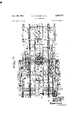
- Fig. l is a fragmentary side view of the improved taping machine showing cartons positioned therein, parts being broken away and in section for clarity;
- Fig. 2 is a fragmentary plan View of the improved taping machine shown in Fig. 1, parts being broken away;
- Fig. 3 is a semi-diagrammatic side view, with parts broken away and in section, showing the relationship of the parts and the positions of the cartons when the cutter-head assembly is in its lowermost position;
- Fig. 4 is a semi-diagrammatic side view similar to Fig. 3 showing the relationship of the parts and the positions of the cartons at two other intervals in a cycle of operation, parts being broken away and in section;
- Fig. is an enlarged fragmentary vertical sectional view taken approximately along the line 5 5 of Fig. 2;
- Fig. 6 is an enlarged fragmentary vertical sectional view taken approximately along the line 6--5 of Fig. 2;
- Fig. 7 is a fragmentary side elevational view of a modied form of the invention wherein the cutter head is actuated by a plunger mechanism mounted on a movable carrier, parts being broken away; and
- Fig. 8 is a fragmentary side elevational view of a modified form of the invention having a stationary carrier and having a cutter head assembly actuated by a xedly mounted plunger mechamsm.
- the frame I9 comprises a pair of spaced parallel rectangular vertical plates II and
- the legs I3 are slotted as at I5 to receive bolts I6.
- the legs I3 are channel shaped in cross section and t around vertically extending bar members I'I which are fixed, as by welding, to the side plates I I and I2.
- the bolts I6 are threaded into suitable apertures in the bars to adjustably position the legs I3 to suit requirements.
- Fixed to the inner surface of the side plates II and I2 are a pair of elongated horizontally extending parallel channel members
- the channel members I8 and I9 are positioned with their flanges extending inwardly toward each other.
- a horizontally extending tie rod is connected at its opposite ends to the side plates and I2 as well as to the channel members I8 and I9.
- 8 and I9 and xed, as by welding, at their opposite ends to said channel members I8 and I3 are transversely extending angle members 2
- , 22 and 23 have horizontally extending co-planar upper surfaces. These angle members are formed with cut-out portions adjacent each end, as at 24, to permit the ends of said angle members to be connected to the web portion of the channels I8 and IS while permitting a substantial portion of said angle members to extend upwardly above the uppermost flange of said channel members, as shown.
- a rotatable transversely extending shaft 21 Fixed on the shaft 2'I are a pair of spaced sprockets 28 and 29 which are disposed on opposite sides of the plate and inwardly of the side plates II and I2, as shown in Fig. 2.
- a tie rod is positioned below and slightly rearwardly of the shaft 21 and extends transversely between the side plates and I2, being connected to said plates at its opposite ends.
- An endless chain 33 extends around the sprockets 28 and 3
- An endless chain 34 extends around the sprockets 29 and 32 and has an upper stretch which extends horizontally rearwardly to a drive sprocket (not shown) which is fixed to the same drive shaft as the drive sprocket for the chain 33.
- a drive shaft (not shown) is, in turn, driven by a suitable prime mover (not shown).
- An elongated angle member 35 extends longitudinally of the machine and has a horizontal flange extending under the chain 33, said angle member having a vertical flange outwardly adjacent the chain 33.
- the angle member 35 may be supported in spaced relation above the transverse angle members 2
- the angle member 35 serves as a track in which the chain 33 can slidably travel in the event said chain becomes slack during use.
- An angle member 33 may be supported in spaced relation above the transverse angle members 2
- the numeral 42 indicates a generally inverted U -shaped vertical carrier structure which extends transversely of the machine and is movable longitudinally thereof".
- 'Ihe carrier 42 has a pair of spaced parallel transversely extending horizontal bars 4S and 42a which are xed at one end to the upper ends of spaced parallel vertically extending bars 44.
- the bars 43 and. 45a are connected at their opposite ends to the upper ends of a pair of spaced parallel vertically extending bars 45.
- the bars 44 are joined at their upper ends by a block 4E, and the bars 45 are joined at their upper ends by a block 41 (see 2).
- the bars 44 are xed to a longitudinally extending vertical plate 43, and the bars 45 are fixed at their lower ends to a longitudinally extending vertical plate 49.
- Extending horizontally rearwardly from the plates 48 and 49 are the legs of U-shaped horizontally extending reinforcing member
- the plate 48 Fixed to the upper surface of the channel I9 is an elongated bar 59 which projects inwardly beyond the inner edge of the upper flange of the channel i9, as shown in Fig. 2.
- the plate 48 is spaced a predetermined distance inwardly of the bar 50, and fixed to the plate 48 are a pair of slide bearing blocks 5
- a pair of slide bearing blocks 5I are fixed to the plate 48 and slidably engage the underside of the bar 52.
- An elongated slide bar 53 similar to the bar 50, is xed to the upper surface of the side channel I8, as shown.
- the vertical plate 4G is spaced a predetermined distance inwardly of the bar 53 and has fixed thereto a pair of bearing blocks 54 which slidably support the end of the carrier 42 adjacent the plate 49, on the slide bar 53.
- the blocks 54 are similar to the blocks 5I, and a pair of slide blocks 55 are fixed to the plate 49 for slidable engagement with the underside of the bar 53. It is apparent that the slide blocks I to 54 and the bars 58 and 53 provide a slidably movable, yet firm, support for the carrier 42.
- a transverse rotatable shaft 56 Journalled in suitable bearings on the plates I I and I2, and intermediate the length of the slide bars 58 and 53, is a transverse rotatable shaft 56. Journalled in suitable bearings on the side plates Il and I2 forwardly of the shaft 56 is a transverse rotatable shaft 51. Sprockets 58 and 58 are fixed to each of the outer ends of the shaft 56, and sprockets 59 and 59 are xed to the shaft 51 outwardly of each of the plates l! and I2. The sprockets 58 and 59 are connected by endless chains 60 which may have their lower stretches travelling over idler rollers 6I mounted on the outer surfaces of the plates Il and I2, as shown in Figs. 1 and 2.
- a sprocket 62 Fixed to the shaft 21 between the plate Il and the sprocket 29 is a sprocket 62, and fixed to the shaft 51 in alinement with the sprocket 82 is a sprocket 63.
- Pivotally mounted at one end on the tie rod 30 between the plate II and the sprocket 32 is an arm 64 having rotatably mounted at its outer end a sprocket B5 which is in alinement with the sprockets 62 and 63.
- An endless chain 66 extends around the sprockets 62, 63 and 65 to provide a drive for the shafts 51 and 56.
- a block 61 Projecting inwardly from the plate I I adjacent the sprocket 65 is a block 61, and fixed, as by welding, to the free end of the arm 54 is a nut 6B.
- An adjustment bolt 68 is threaded through the nut 88 and has its end in abutment with the block 61. By tightening the bolt 68 the nut 68 may be urged away from the block 61 and the sprocket 55 can be thus moved in a chain tightening direction.
- a jamb nut 10 is provided on the bolt 69 adjacent the nut 68 to lock the bolt 69 in a desired position of adjustment.
- cam members 1l and 12 Fixedly mounted on the shaft 56 inwardly of the plates 48 and 49 are a pair of cam members 1l and 12 which have cam grooves formed in their outer faces.
- a bar 13 having rotatably mounted at its lower end a cam roller 14 which extends horizontally into the groove of the cam 1I.
- a bar 15 depends from the forward end portion of the plate 49 and carries at its lower end a rotatable cam roller 16 which extends horizontally into the groove of the cam 12.
- the cam members 1I and 12 are provided with identical cam grooves, said grooves each having a portion of constant radius, a portion of increasing radius, and a portion of decreasing radius, as shown in Figs. l, 3 and 4. It is apparent that rotation of the cams 1
- the rollers 14 and 16 Upon reaching the portion of maximum radius of the cam grooves, the rollers 14 and 16 follow the portions of decreasing radius of the cam grooves, and the carrier is thereby moved back toward its original position.
- the carrier 42 is held in the position shown in Fig. 1, until the followers 14 and 16 again move into the portions of increasing ra#- dius, at which time a new cycle of reciprocatlon is begun.
- the cam grooves are of such conformation that when the followers 14 and 16 are travelling in the portions of increasing radius thereof, the carrier 42 is moved in the same direction as the upper stretches of the chains 33 and 34, and for a predetermined distance is moved at substantially the same speed as said chains.
- a bar 11 Extending transversely of the machine between the vertical rods 44 and the vertical rods 45, and projecting outwardly beyond the side lates I I and I 2, is a bar 11.
- the bar 11 is mounted in suitable slide blocks which are interposed between the bars 44 and between the bars 45, and which are in slidable contact with the opposed surfaces of said bars.
- cam members 18 and 19 are each formed with a cam groove on its inner face, the major portion of each cam groove having a constant radius and the remaining portion of said cam groove having a shorter radius as is clearly shown in Fig. 1.
- a pair of levers 88 are pivotally mounted intermediate their length on the outer surfaces of the side plates II and I2.
- the levers 88 are movable in a vertical plane inwardly of the cams 18 and 19 and have their rear ends pivotally connected to the outer ends of the transverse bar 11 through links SI.
- the transverse bar 11 carries intermediate its length a cutter head assembly 84 to be described hereinafter.
- Suitable counter weights 82 may be attached to the forward ends of the levers 88 to counter-balance the forces urging the opposite ends of said levers downwardly.
- a rotatable cam following roller 83 Carried by the levers 8D above the shaft 51 is a rotatable cam following roller 83 which extends horizontally into the groove of the cam 18, as is clearly shown in Fig. 1. It is apparent that rotation of the cams 18 and 19 in the direction indicated by the arrow in Fig. 1 causes a relatively rapid lowering of the rod 'I1 followed by an equally rapid raising of said rod to its original level. It is also apparent that the rod 11 will be thereafter held at its original level until the completion of one revolution of the cams 18 and 19.
- the numeral 84 indicates a cutter head assembly which is carried by and depends from the transverse bar 11 at a point intermediate its length.
- the cutter head assembly 84 is comprised of a pair of spaced parallel vertical bars 85 and 86 which are rectangularly recessed at their upper ends to receive the bar 11 and which are fixed to the bar 11 by means of suitable screws 81 (see Fig. 6).
- Formed in the bottom surface of the bar 85 adjacent its forward end is a vertical blade-receiving slot 81, and formed in the lower surface of the bar 86 adjacent the rear end thereof is a vertical blade-receiving slot 88.
- a cutter blade 89 preferably having a serrated lower edge, is removably fixed at one end in the slot 81 and is removably fixed at its other end in the slot 88.
- the end of the blade in the slot 81 is higher than the opposite end of said blade, thereby causing the lower edge of said blade to be disposed at an angle to horizontal as shown in Figs. 5 and 6.
- the slots 81 and 88 position the blade 8S so that it extends diagonally between the bars 85 and 86 rather than parallel with the bar 11.
- Pivotally mounted on the shaft 90 are a pair of spaced arms 9
- the arm 92 is positioned adjacent the bar S5 and the bar 9
- a helical spring 93 is positioned around the shaft 90 and has one end extending through a suitable aperture in the arm 92. The opposite end of the spring 93 extends through a suitable aperture in the arm 9
- the free end of the arm S2 is apertured to threadedly receive one end of a shaft 94 which extends substantially parallel with the shaft 90.
- a lock nut 95 locks the shaft 34 to the arm 32.
- Rotatably mounted on the shaft 94 is a cylindrical roller SS of sponge rubber or other suitable material.
- the roller 96 is maintained on the shaft 94 by any suitable means such as a cotter key 91 extending through a suitable aperture in the end of said shaft.
- is apertured to threadedly receive a shaft 98 in the same manner as the shaft 94 is carried by the arm 92.
- a cylindrical roller 93 similar to the roller 96, is rotatably mounted on the shaft 98 and is held on said shaft by any suitable means such as the cotter key which extends through a suitable aperture in the opposite end of said shaft.
- Fixed to the bar 85 is an angularly disposed L-shaped bracket
- 02 is threaded through the bracket
- 02 is provided with a lock nut
- 08 each having an elongated leg and a relatively short leg, are formed with elongated slots
- 08 are connected to and depend from a central portion of the rearward transverse bar 43 of the carrier 42. Bolts
- a spacer block spaces each of the members
- 08 because of their position substantially midway of the length of the bar 63, are rearwardly adjacent the cutterhead assembly 84.
- 2 is formed with an aperture
- 4 having a bore of substantially the same diameter as that of the aperture i
- the plate l 2 is formed with an aperture l
- 5 is preferably fixed to the upper surface of the plate
- 1 is slidably positioned in the sleeve
- 1 is threaded to receive a pair of nuts H8 which abut the upper end of the sleeve i ifi.
- a round shaft I9 is positioned in the sleeve
- 9 has its upper end threaded to receive a pair of nuts
- 9, is a transversely extending horizontal shaft
- 22 is positioned around the shaft
- 23 is positioned around the shaft
- 24 is positioned on the shaft
- 25 is positioned around the shaft
- 26 of sponge rubber or other suitable material, is rotatably positioned on the shaft IZI, as shown.
- 08 is designated generally as the pressure roller assembly
- 28 which is substantially identical to the pressure roller assembly
- 28 is longitudinally alined with the cutter-head assembly 84 and with the pressure roller assembly
- 26 Fixedly connected to the longitudinal frame channels
- 26 rotatably supports a. horizontal roller
- the improved taping machine is installed in a conveyor system wherein a feed conveyor (not shown) delivers cartons to be taped onto the rear end of the plate 25, in longitudinal alinement.
- on the chains 33 and 34 engage the rear ends of said cartons and move said cartons along the plate 25 through the machine in equally spaced longitudinally alined relation.
- the cartons are discharged onto a suitable delivery conveyor (not shown).
- the cartons shown in all of the views are designated by the numerals
- a roll of adhesive tape (not shown), such gummed paper tape, is mounted on the improved machine above and rearwardly of the roller
- 35 is led from said roll and 9. under the roller
- 35 is suitably moistened before it reaches the roller
- the cartons of the type sealed by the improved machine are preferably those having foldable side and end cover flaps, and before said cartons are delivered onto the plate 25, said cover aps are folded inwardly, as shown in Fig. 6, by conventional flap folding mechanisms (not shown).
- the flap folding mechanisms rst fold the end flaps inwardly and then fold the side flaps inwardly, the inner edges of said side flaps meeting substantially along the longitudinal center line of the carton.
- 35 is applied to the tops of the cartons, it too is positioned substantially along the longitudinal center line of said cartons, thereby covering the line of juncture of the folded side flaps and sealingly connecting said side flaps together.
- 35 to the tops of the moving cartons causes said tape to be drawn from its roll at a substantially constant speed equal to the speed of advancement of the cartons.
- 35 as applied to the cartons adjacent the roller
- the cutter head assembly 84 is designed to sever the tape
- 28 firmly press down the cover naps of the cartons adjacent the cutterhead assembly 84 so that the application of the severed adhesive tape ends to the end walls of the cartons results in said tape ends holding the cover flaps in the desired downwardly folded position.
- 29 insure rm adhesion of the tape
- Figs. 1, 2, 5 and 6 show the cutter-head assembly, the carrier 42, and the cartons in position to being a cycle of operation. It will be noted that when the parts are in position to being a cycle the cutter-head and the carrier are longitudinally positioned substantially midway between the cartons
- the prime mover (not shown), through the chains 33 and 34 and the flights 4 I, moves the cartons forwardly along the plate 25 at substantially constant speed. As the chains 33 and 34 are so moved, the cams and 12 are rotated in the direction indicated by the arrows by the interconnecting chain drive provided by the chains 6G and 60. It will be noted that the cutter-head assembly 84 is spaced above the tape
- the cam 12 maintains the carrier 42 and the pressure roller assemblies
- the cam 18 rotates from the position of Fig. 1 to the position of Fig. 3, the
- 35 causes the blade 89 to begin the severance at one edge of the tape
- Further ⁇ downward movement of the cutterhead 84 causes the rollers 96 and 99 to engage the tape
- 28 maintain a constant downward pressure on the upper surface of the tape
- FIG. 3 shows the cutter-head assembly 84 in its lowermost position after having severed the tape
- the cartons are moved forwardly at their normal constant speed, and the carton
- the roller of each of said assemblies rollingly contacts, with a rm downward pressure, the entire length of tape
- 21 rollingly contacts with a firm downward pressure, the tape applied to the forward end portion of the top of the folded cover flaps of the carton
- the improved taping machine is adapted for use in taping cartons f different heights. For example, if cartons of smaller height than cartons
- the improved taping machine provides a means for eilciently and positively tape sealing cartons.
- To open a carton sealed by the improved machine it is only necessary to slit the tape longitudinally at the juncture of the cover flaps and transversely at the edges of said cover aps at each end of the carton.
- the cover flaps may then be readily opened to provide access to the interior of the carton.
- a carton opened in this manner is not damaged in any way, and unless mistreated, can be reused several times.
- said carton upon beingr returned to the brewery with empty bottles therein, may be refilled With full bottles and be again tape sealed for shipment.
- Figs. '1 and 8 show modified forms of the invention having embodied therein a power plunger for actuating the vertically reciprocatable cutter head. It will be noted that the cam and lever mechanism embodied in the principal form of the invention to vertically reciprocate the cutter head is eliminated in the form of the invention shown in Fig. '7. In Figs. 7 and 8 the parts of the machine which are substantially identical with analogous parts of the principal form of the invention are indicated by the same reference characters primed.
- which is preferably a double-acting air pressure operated ram (but which may be any equivalent mechanism such as another form of iluid pressure operated ram, or a solenoid) is fixed to the transverse bars 43 above the cutter head 84'.
- the mechanism IM is provided with an axially rcciprocatable rod or plunger
- Suitable iiuid or electrical connections (not shown) as well as suitable switches and/or valves (also not shown) are provided to control the operation of the cutter head 84 and to synehronize the operation thereof with the movement of the cartons.
- Fig. 8 discloses a form of the invention which is adapted for use with a conveyor system on which the cartons are moved relatively slowly.
- the carrier 42 is xedly mounted on the frame members I8' and I3', and therefore, the cam mechanism for horizontally reciprocating the carrier 42 of the principal form is eliminated.
- 44 are preferably slotted at their lower ends, as at
- 44 support a transverse member
- 48 is iixed at its upper end to the plate
- 43 is similar to the power plunger mechanism
- the plunger 49 is connected to the transverse bar 11 for vertically reciprocating said bar and the cutter head 8f3. Suitable fluid or electrical connections (not shown), as well as suitable switches and/or valves are provided to control the operation of the power plunger mechanism
- 48 can be adjusted readily. All that need be done to accomplish this is to loosen the bolts
- 28' may be vertically adjusted in the same manner as the assemblies
- a taping machine having a conveyor for moving spaced, alined cartons longitudinally through said machine and having means for applying tape to the tops of said cartons as said cartons are moved forwardly through said machine; a carrier longitudinally reciprocatably mounted on said machine and including a head reciprocatable at right angles to the path of travel of the carriers; carrier actuating mechanism connected to said conveyor in timed relationship in a manner to move said carrier rearwardly to a predetermined position relative to a pair of successive cartons on said conveyor and to move said carrier forwardly with and at the same speed as said conveyor for a predetermined distance; pressure members mounted on said head to deflect and press the out ends of tape against the ends of adjacent cartons; and additional spaced pressure members mounted on said carrier in positions to continuously engage tape applied to the tops of the adjacent end portions of said pair of successive cartons at all times that said carrier is in said predetermined position and throughout the forward movement of said carrier.
- a taping machine having a conveyor for moving spaced, alined cartons longitudinally through said machine and having means for applying tape to the tops of said cartons as said cartons are moved through said machine; a carrier disposed adjacent the course of travel of cartons on said conveyor; a movable cutting head including a tape severing knife and spaced end-sealing pressure members flanking said knife mounted on said carrier for movement thereon transversely to the course of travel of cartons on said conveyor; cutting head actuating mechanism connected to said conveyor in timed relation therewith operative to cause said cutting head to move between cartons to cut said tape and press the cut ends of said tape against the adjacent carton ends when said cutting head is alined with a space between adjacent cartons; additional spaced pressure members more widely spaced than said rst mentioned pressure members disposed on said carrier on opposite sides of said knife; and mounting means engaging said additional pressure members for maintaining the longitudinal spacing between said additional pressure members and said knife constant and for supporting said additional pressure members in position to be engageable with and to apply downward
Description
Sept. 29, 1953 A. A. WAGNER ETAL TAPING MACHINE 5 Sheets-Sheet l Filed April 8. 1950 Sept. 29, 1953 A. A. WAGNER ETAL TAPING MACHINE 5 Sheets-Sheet 2 Filed April 8. 1950 Sept 29, 1953 A. A. WAGNER ET A1. 2,553,727
TAPING MACHINE Filed April 8, 1950 5 Sheets-Sheet 3 I VENTORJ w gm By @da M Mmbm Sept. 29, 1953 A. A. WAGNER ETAL TAPING MACHINE Filed April 8. 1950 5 Sheets-Sheet 4 Sept. 29, 1953 A. A. WAGNER ET AL 2,653,727
TAPING MACHINE Filed April 8, 1950 5 Sheets-Sheet 5 INVENTORS 4 a/ L md5/M Patented Sept. 29, 1953 TAPING MACHINE Adolph A. Wagner, Milwaukee, Arnold J. Werner, Elm Grove, and William R. Ross, Milwaukee,
Wis.
Application April 8, 1950, Serial No. 154,782
(Cl. 21S-22) 2 Claims.
This invention relates to improvements in taping machines, and more particularly, to machines for tape sealing cartons.
In recent years it has become increasingly popular to package commodities in cartons formed of fibrous material such as those materials commonly known as ber-board, kraft, corrugated cardboard, or the like. Many forms of canned and bottled goods are now being shipped in this type of carton which will hereinafter be referred to broadly by the term fiberboard, it being understood that this term is meant to cover any of the above-mentioned materials or any equivalent material.
The fiber-board cartons of the type referred to are usually rectangular in shape and have foldable cover flaps forming extensions of the side and end walls thereof. It has been standard practice heretofore, after the carton is lled, to fold the end flaps of the carton inwardly toward each other into a common plane and to then fold the side cover aps inwardly toward each other and into contact with the upper surfaces of the folded end cover naps. The package was sealed by gluing the previously folded side cover naps to the end cover flaps.
In manually opening a fiber-board carton of the type having itsl cover flaps sealed with glue in the manner just described, it is usually irnpossible to avoid tearing or cutting the cover flaps, thereby rendering the carton uniit for reuse.
With the above in mind, it is a general object oi the present invention to provide an improved device for sealing fiber-board cartons having oldable cover naps, said device sealing said cartons in a manner so that the cover flaps can be easily opened without any substantial damage thereto, thereby making reuse of said cartons possible and entirely feasible.
A further object of the invention is to provide an improved device of the class described having a single pair of spring loaded pressure rollers which are mounted for reciprocating movement longitudinaily of the path of movement of the cartons moving through the machine, said rollers being operable to maintain a downward pressure on the end portions of the taped carton tops for a sustained predetermined period during movement in the same direction as said cartons and at the same speed, and said rollers contacting the intermediate portions of the taped carton tops during movement in a direction counter to the direction of movement of he cartons.
A further object of the invention is to provide an improved device of the class described which is constructed in a manner to be readily adjustable for tape sealing cartons of various sizes.
A further object of the invention is to provide an improved taping machine of the class described wherein tape from a single roll is applied to the tops of cartons as said cartons are moved through the machine in equally spaced and alined relationship, said device having novel means for severing the tape between the moving cartons and for applying the severed ends of the tape sections to the end walls of the cartons.
A further object of the invention is to provide an improved device of the class described having a vertically reciprocating knife for severing the tape between adjacent cartons on a conveyor', said knife being disposed at an angle to the plane ofthe tape to insure a proper cutting rather than a breaking action.
' A furtherl object of the invention is to provide an improved machine of the class described having a pair of spring loaded rollers mounted for swingable movement as well as for vertical reciprocatable movement with the severing knife, said rollers being operable to apply the severed tape ends to the adjacent end walls of the cartons.
A further object of the invention is to provide an improved taping machine wherein the vertically reciprocating tape severing mechanism is actuated by a vertically reciprocating plunger mounted thereabove.
With the above and other objects in view, the invention consists of the improved taping machine and all of its parts and combinations as set forth in the claims, and all equivalents thereof.
In the drawings accompanying and forming a part of this specification, wherein are shown three forms of the invention, and wherein the same characters of reference indicate the same parts in all of the views:
Fig. l is a fragmentary side view of the improved taping machine showing cartons positioned therein, parts being broken away and in section for clarity;
Fig. 2 is a fragmentary plan View of the improved taping machine shown in Fig. 1, parts being broken away;
Fig. 3 is a semi-diagrammatic side view, with parts broken away and in section, showing the relationship of the parts and the positions of the cartons when the cutter-head assembly is in its lowermost position;
Fig. 4 is a semi-diagrammatic side view similar to Fig. 3 showing the relationship of the parts and the positions of the cartons at two other intervals in a cycle of operation, parts being broken away and in section;
Fig. is an enlarged fragmentary vertical sectional view taken approximately along the line 5 5 of Fig. 2;
Fig. 6 is an enlarged fragmentary vertical sectional view taken approximately along the line 6--5 of Fig. 2;
Fig. 7 is a fragmentary side elevational view of a modied form of the invention wherein the cutter head is actuated by a plunger mechanism mounted on a movable carrier, parts being broken away; and
Fig. 8 is a fragmentary side elevational view of a modified form of the invention having a stationary carrier and having a cutter head assembly actuated by a xedly mounted plunger mechamsm.
Referring to Figs. 1 and 2 of the drawings, it will appear that the improved taping machine has a frame indicated by the numeral I0. The frame I9 comprises a pair of spaced parallel rectangular vertical plates II and |2. adjustably connected to each of the plates I I and I2 adjacent each end thereof is a depending leg I3 having a base plate I4. The legs I3 are slotted as at I5 to receive bolts I6. The legs I3 are channel shaped in cross section and t around vertically extending bar members I'I which are fixed, as by welding, to the side plates I I and I2. The bolts I6 are threaded into suitable apertures in the bars to adjustably position the legs I3 to suit requirements. Fixed to the inner surface of the side plates II and I2 are a pair of elongated horizontally extending parallel channel members |8 and I9. The channel members I8 and I9 are positioned with their flanges extending inwardly toward each other.
A horizontally extending tie rod is connected at its opposite ends to the side plates and I2 as well as to the channel members I8 and I9. Extending between the channel members |8 and I9 and xed, as by welding, at their opposite ends to said channel members I8 and I3 are transversely extending angle members 2|, 22 and 23. The angle members 2|, 22 and 23 have horizontally extending co-planar upper surfaces. These angle members are formed with cut-out portions adjacent each end, as at 24, to permit the ends of said angle members to be connected to the web portion of the channels I8 and IS while permitting a substantial portion of said angle members to extend upwardly above the uppermost flange of said channel members, as shown. Extending longitudinally of the machine substantially midway between the side plates and I2 and positioned on the upper surfaces of the angled members 2 I, 22 and 23 is an elongated horizontal plate 2.. Fixed to the upper surface of the plate 25 adjacent each edge thereof is an elongated bar 26.
Journaled in suitable bearings adjacent the upper front (lefthand in Fig. 1) corners of the side plates and I2, is a rotatable transversely extending shaft 21. Fixed on the shaft 2'I are a pair of spaced sprockets 28 and 29 which are disposed on opposite sides of the plate and inwardly of the side plates II and I2, as shown in Fig. 2. A tie rod is positioned below and slightly rearwardly of the shaft 21 and extends transversely between the side plates and I2, being connected to said plates at its opposite ends. Rotatably mounted on the tie rod 30 and aligned Vertically in the same vertical planes with the sprockets 28 and 29 respectively, are a pair of idler sprockets 3| and 32. An endless chain 33 extends around the sprockets 28 and 3| and has an upper horizontal stretch which extends rearwardly parallel with the plate 25 to a drive sprocket (not shown). An endless chain 34 extends around the sprockets 29 and 32 and has an upper stretch which extends horizontally rearwardly to a drive sprocket (not shown) which is fixed to the same drive shaft as the drive sprocket for the chain 33. A drive shaft (not shown) is, in turn, driven by a suitable prime mover (not shown).
.An elongated angle member 35 extends longitudinally of the machine and has a horizontal flange extending under the chain 33, said angle member having a vertical flange outwardly adjacent the chain 33. The angle member 35 may be supported in spaced relation above the transverse angle members 2|, 22 and 23 by suitable blackets, such as those shown at 36 and 31. The angle member 35 serves as a track in which the chain 33 can slidably travel in the event said chain becomes slack during use. An angle member 33 may be supported in spaced relation above the transverse angle members 2|, 22 and 23 by suitable brackets 39 and 40 and is associated with the chain 34 in the same manner as the angle member 35 is associated with the chain 33.
Extending transversely between the endless chains 33 and 34 and connected at their opposite ends to said chains, are equally spaced conveyor flights 4|. The flights 4| on the upper stretch of the chains 33 and 34 extend transversely above the plate 25 and the bars 26 thereon, as clearly shown in Fig. l. The chains 33 and 34 are moved by their driving sprockets in a direction to cause the upper stretches to move from the rear forwardly (from right to left, as shown in Figs. l to 4).
The numeral 42 indicates a generally inverted U -shaped vertical carrier structure which extends transversely of the machine and is movable longitudinally thereof". 'Ihe carrier 42 has a pair of spaced parallel transversely extending horizontal bars 4S and 42a which are xed at one end to the upper ends of spaced parallel vertically extending bars 44. The bars 43 and. 45a are connected at their opposite ends to the upper ends of a pair of spaced parallel vertically extending bars 45. The bars 44 are joined at their upper ends by a block 4E, and the bars 45 are joined at their upper ends by a block 41 (see 2). At their lower ends, the bars 44 are xed to a longitudinally extending vertical plate 43, and the bars 45 are fixed at their lower ends to a longitudinally extending vertical plate 49. Extending horizontally rearwardly from the plates 48 and 49 are the legs of U-shaped horizontally extending reinforcing member |4l which rigidly connects the plate 48 to the plate 49.
Fixed to the upper surface of the channel I9 is an elongated bar 59 which projects inwardly beyond the inner edge of the upper flange of the channel i9, as shown in Fig. 2. The plate 48 is spaced a predetermined distance inwardly of the bar 50, and fixed to the plate 48 are a pair of slide bearing blocks 5| which slidably support one end of the carrier 42 on the bar 5l). A pair of slide bearing blocks 5I are fixed to the plate 48 and slidably engage the underside of the bar 52.
An elongated slide bar 53, similar to the bar 50, is xed to the upper surface of the side channel I8, as shown. The vertical plate 4G is spaced a predetermined distance inwardly of the bar 53 and has fixed thereto a pair of bearing blocks 54 which slidably support the end of the carrier 42 adjacent the plate 49, on the slide bar 53. The blocks 54 are similar to the blocks 5I, and a pair of slide blocks 55 are fixed to the plate 49 for slidable engagement with the underside of the bar 53. It is apparent that the slide blocks I to 54 and the bars 58 and 53 provide a slidably movable, yet firm, support for the carrier 42.
Journalled in suitable bearings on the plates I I and I2, and intermediate the length of the slide bars 58 and 53, is a transverse rotatable shaft 56. Journalled in suitable bearings on the side plates Il and I2 forwardly of the shaft 56 is a transverse rotatable shaft 51. Sprockets 58 and 58 are fixed to each of the outer ends of the shaft 56, and sprockets 59 and 59 are xed to the shaft 51 outwardly of each of the plates l! and I2. The sprockets 58 and 59 are connected by endless chains 60 which may have their lower stretches travelling over idler rollers 6I mounted on the outer surfaces of the plates Il and I2, as shown in Figs. 1 and 2.
Fixed to the shaft 21 between the plate Il and the sprocket 29 is a sprocket 62, and fixed to the shaft 51 in alinement with the sprocket 82 is a sprocket 63. Pivotally mounted at one end on the tie rod 30 between the plate II and the sprocket 32 is an arm 64 having rotatably mounted at its outer end a sprocket B5 which is in alinement with the sprockets 62 and 63. An endless chain 66 extends around the sprockets 62, 63 and 65 to provide a drive for the shafts 51 and 56.
Projecting inwardly from the plate I I adjacent the sprocket 65 is a block 61, and fixed, as by welding, to the free end of the arm 54 is a nut 6B. An adjustment bolt 68 is threaded through the nut 88 and has its end in abutment with the block 61. By tightening the bolt 68 the nut 68 may be urged away from the block 61 and the sprocket 55 can be thus moved in a chain tightening direction. A jamb nut 10 is provided on the bolt 69 adjacent the nut 68 to lock the bolt 69 in a desired position of adjustment.
Fixedly mounted on the shaft 56 inwardly of the plates 48 and 49 are a pair of cam members 1l and 12 which have cam grooves formed in their outer faces. Depending from the plate 48 adjacent the front end thereof is a bar 13 having rotatably mounted at its lower end a cam roller 14 which extends horizontally into the groove of the cam 1I. A bar 15 depends from the forward end portion of the plate 49 and carries at its lower end a rotatable cam roller 16 which extends horizontally into the groove of the cam 12.
The cam members 1I and 12 are provided with identical cam grooves, said grooves each having a portion of constant radius, a portion of increasing radius, and a portion of decreasing radius, as shown in Figs. l, 3 and 4. It is apparent that rotation of the cams 1| and 12 in the direction indicated by the arrows in Figs. 1, 3 and 4 cause movement of the carrier 42 to the left as the followers 14 and 16 follow the portion of increasing radius of the cam grooves.
Upon reaching the portion of maximum radius of the cam grooves, the rollers 14 and 16 follow the portions of decreasing radius of the cam grooves, and the carrier is thereby moved back toward its original position. When the followers 14 and 16 leave the portions of decreasing radius of the cam grooves and enter the portions of the constant radius, the carrier 42 is held in the position shown in Fig. 1, until the followers 14 and 16 again move into the portions of increasing ra#- dius, at which time a new cycle of reciprocatlon is begun. The cam grooves are of such conformation that when the followers 14 and 16 are travelling in the portions of increasing radius thereof, the carrier 42 is moved in the same direction as the upper stretches of the chains 33 and 34, and for a predetermined distance is moved at substantially the same speed as said chains.
Extending transversely of the machine between the vertical rods 44 and the vertical rods 45, and projecting outwardly beyond the side lates I I and I 2, is a bar 11. The bar 11 is mounted in suitable slide blocks which are interposed between the bars 44 and between the bars 45, and which are in slidable contact with the opposed surfaces of said bars.
Mounted on the outer ends of the shaft 51 are a pair of cam members 18 and 19. The cam members 18 and 19 are each formed with a cam groove on its inner face, the major portion of each cam groove having a constant radius and the remaining portion of said cam groove having a shorter radius as is clearly shown in Fig. 1.
A pair of levers 88 are pivotally mounted intermediate their length on the outer surfaces of the side plates II and I2. The levers 88 are movable in a vertical plane inwardly of the cams 18 and 19 and have their rear ends pivotally connected to the outer ends of the transverse bar 11 through links SI. The transverse bar 11 carries intermediate its length a cutter head assembly 84 to be described hereinafter. Suitable counter weights 82 may be attached to the forward ends of the levers 88 to counter-balance the forces urging the opposite ends of said levers downwardly.
Carried by the levers 8D above the shaft 51 is a rotatable cam following roller 83 which extends horizontally into the groove of the cam 18, as is clearly shown in Fig. 1. It is apparent that rotation of the cams 18 and 19 in the direction indicated by the arrow in Fig. 1 causes a relatively rapid lowering of the rod 'I1 followed by an equally rapid raising of said rod to its original level. It is also apparent that the rod 11 will be thereafter held at its original level until the completion of one revolution of the cams 18 and 19.
Referring now to Figs. 5 and 6, the numeral 84 indicates a cutter head assembly which is carried by and depends from the transverse bar 11 at a point intermediate its length. The cutter head assembly 84 is comprised of a pair of spaced parallel vertical bars 85 and 86 which are rectangularly recessed at their upper ends to receive the bar 11 and which are fixed to the bar 11 by means of suitable screws 81 (see Fig. 6). Formed in the bottom surface of the bar 85 adjacent its forward end is a vertical blade-receiving slot 81, and formed in the lower surface of the bar 86 adjacent the rear end thereof is a vertical blade-receiving slot 88. A cutter blade 89, preferably having a serrated lower edge, is removably fixed at one end in the slot 81 and is removably fixed at its other end in the slot 88.
The end of the blade in the slot 81 is higher than the opposite end of said blade, thereby causing the lower edge of said blade to be disposed at an angle to horizontal as shown in Figs. 5 and 6. In addition, the slots 81 and 88 position the blade 8S so that it extends diagonally between the bars 85 and 86 rather than parallel with the bar 11.
Referring to Fig. 6, it will be noted that xedly mounted in suitable apertures in the bars 85 and 88 and positioned adjacent and parallel with the bottom of the transverse bar 11, is a shaft 90.
Pivotally mounted on the shaft 90 are a pair of spaced arms 9| and 92. The arm 92 is positioned adjacent the bar S5 and the bar 9| is positioned adjacent the bar 86. A helical spring 93 is positioned around the shaft 90 and has one end extending through a suitable aperture in the arm 92. The opposite end of the spring 93 extends through a suitable aperture in the arm 9|, and said spring urges the arms 3| and 92 in opposite directions away from each other.
The free end of the arm S2 is apertured to threadedly receive one end of a shaft 94 which extends substantially parallel with the shaft 90. A lock nut 95 locks the shaft 34 to the arm 32. Rotatably mounted on the shaft 94 is a cylindrical roller SS of sponge rubber or other suitable material. The roller 96 is maintained on the shaft 94 by any suitable means such as a cotter key 91 extending through a suitable aperture in the end of said shaft.
The end of the arm 9| is apertured to threadedly receive a shaft 98 in the same manner as the shaft 94 is carried by the arm 92. A cylindrical roller 93, similar to the roller 96, is rotatably mounted on the shaft 98 and is held on said shaft by any suitable means such as the cotter key which extends through a suitable aperture in the opposite end of said shaft. Fixed to the bar 85 is an angularly disposed L-shaped bracket |0| having a portion projecting over the arm 92. A set screw |02 is threaded through the bracket |0| and has one end in abutment with the arm 92, as shown, to limit the movement of said arm and of the roller S6. The adjustment screw |02 is provided with a lock nut |03.
Fixed to the bar 8S is an angularly disposed L-shaped bracket |04 having a portion projecting over the arm 9|. A set screw |05 is threaded through the bracket |04 and has an end in abutment with the arm 0| to limit the movement of said arm and of the roller 99. The adjustment screw is provided with a lock nut |06. It is apparent that the spring 93 urges the arms 9| and 92 into contact with the adjustment screws |05 and |02, respectively, and that when said arms are moved toward each other the spring 93 is subjected to deformation.
A pair of parallel L-shaped members |01 and |08 each having an elongated leg and a relatively short leg, are formed with elongated slots |09 adjacent the end of the elongated legs thereof. The members |01 and |08 are connected to and depend from a central portion of the rearward transverse bar 43 of the carrier 42. Bolts ||0 project through the slots |09 and are threaded into the bar 43. A spacer block spaces each of the members |01 and |08 from the bar 43, as shown, and the bolts ||0 extend through said blocks. The members |01 and |08, because of their position substantially midway of the length of the bar 63, are rearwardly adjacent the cutterhead assembly 84.
Bolted to the undersides of the short arms of the members |01 and |08 is a transversely extending horizontal plate |l2. The plate ||2 is formed with an aperture ||3 therethrough between the member i0? and the adjacent end of plate. Preferably fixed to the upper surface of the plate i |2 in registration with the aperture H3 is a vertically extending sleeve ||4 having a bore of substantially the same diameter as that of the aperture i |3. The plate l 2 is formed with an aperture l |5 therethrough positioned between the member |08 and the adjacent end of said plate. A vertically extending sleeve H6, having a bore diameter substantially equal to that of the aperture ||5 is preferably fixed to the upper surface of the plate ||2 in registration with the aperture ||5.
A round shaft ||1 is slidably positioned in the sleeve ||4 and in the aperture ||3 and projects downwardly below the plate I |2. IThe upper end of the shaft ||1 is threaded to receive a pair of nuts H8 which abut the upper end of the sleeve i ifi. A round shaft I9 is positioned in the sleeve ||6 and in the aperture ||5 and projects below the plate H2. rEhe shaft ||9 has its upper end threaded to receive a pair of nuts |23 which abut the upper end of the sleeve HB. Connected at its opposite ends to the lower ends of the shafts ||1 and |9, is a transversely extending horizontal shaft |2|. A washer |22 is positioned around the shaft ||1 and rests on the shaft |2|, as shown, and a helical compression spring |23 is positioned around the shaft ||1 between the washer |22 and the plate ||2. A washer |24 is positioned on the shaft ||S and rests on the shaft |2|, as shown, and a helical compression spring |25 is positioned around the shaft ||3 between the plate ||2 and the washer |24. A cylindrical roller |26, of sponge rubber or other suitable material, is rotatably positioned on the shaft IZI, as shown. It is apparent that the springs E23 and |25 urge the shafts Hi, H9 and |2|, along with the roller |26, downwardly to normally maintain the nuts ||3 and 22,x in abutment with the upper end of the sleeves ||4 and i IE respectively.
For the purposes of brevity, the roller assembly supported by the members |31 and |08 is designated generally as the pressure roller assembly |21. A pressure roller assembly |28 which is substantially identical to the pressure roller assembly |21 is connected to and depends from the forward surface of the forward transverse bar 43, as shown in Figs. l, 2 and 5. The pressure roller assembly |28 is longitudinally alined with the cutter-head assembly 84 and with the pressure roller assembly |21.
Fixedly connected to the longitudinal frame channels |8 and |9 and extending transversely above and across the longitudinal plate E5 at a point spaced rearwardly of the reciproca-table carrier 52, is an inverted U-shaped frame |29. The frame |26 rotatably supports a. horizontal roller |30 in a position in longitudinal alinement with. the cutter-head assembly 84 and the pressure roller assemblies |21 and |28, the roller |30 being spaced a predetermined distance above the plate 25.
Operation In operation, the improved taping machine is installed in a conveyor system wherein a feed conveyor (not shown) delivers cartons to be taped onto the rear end of the plate 25, in longitudinal alinement. The flights 4| on the chains 33 and 34 engage the rear ends of said cartons and move said cartons along the plate 25 through the machine in equally spaced longitudinally alined relation. At the forward end of the machine, the cartons are discharged onto a suitable delivery conveyor (not shown). For the purpose of explanation, the cartons shown in all of the views are designated by the numerals |31. |32, |33 and |34.
A roll of adhesive tape, (not shown), such gummed paper tape, is mounted on the improved machine above and rearwardly of the roller |30. An extent of tape |35 is led from said roll and 9. under the roller |30, which applies said tape .to the tops of the cartons as said cartons move thereunder along the plate 25. The tape |35 is suitably moistened before it reaches the roller |30.
The cartons of the type sealed by the improved machine, are preferably those having foldable side and end cover flaps, and before said cartons are delivered onto the plate 25, said cover aps are folded inwardly, as shown in Fig. 6, by conventional flap folding mechanisms (not shown). The flap folding mechanisms rst fold the end flaps inwardly and then fold the side flaps inwardly, the inner edges of said side flaps meeting substantially along the longitudinal center line of the carton. As the tape |35 is applied to the tops of the cartons, it too is positioned substantially along the longitudinal center line of said cartons, thereby covering the line of juncture of the folded side flaps and sealingly connecting said side flaps together. The adhesion of the tape |35 to the tops of the moving cartons causes said tape to be drawn from its roll at a substantially constant speed equal to the speed of advancement of the cartons.
Referring to Figs. 1 and 2, it will be noted that the tape |35, as applied to the cartons adjacent the roller |30, extends from the top of one carton horizontally to the top of the next adjacent carton as shown at |36 and |31. The cutter head assembly 84 is designed to sever the tape |35 between each pair of adjacent cartons and to apply the severed ends of the tape to the adjacent end walls of the cartons. The pressure roller assemblies |21 and |28 firmly press down the cover naps of the cartons adjacent the cutterhead assembly 84 so that the application of the severed adhesive tape ends to the end walls of the cartons results in said tape ends holding the cover flaps in the desired downwardly folded position. In addition, the pressure roller assemblies |21 and |29 insure rm adhesion of the tape |35 to the tops of the cover flaps by a rolling pressure contact on said tape between severing operations, as will be further described in detail hereinafter.
Figs. 1, 2, 5 and 6 show the cutter-head assembly, the carrier 42, and the cartons in position to being a cycle of operation. It will be noted that when the parts are in position to being a cycle the cutter-head and the carrier are longitudinally positioned substantially midway between the cartons |32 and |33. The carton |3| is shown as completely taped, and the carton |32 is shown as having the top and the forward end thereof taped. As the cycle begins, the prime mover (not shown), through the chains 33 and 34 and the flights 4 I, moves the cartons forwardly along the plate 25 at substantially constant speed. As the chains 33 and 34 are so moved, the cams and 12 are rotated in the direction indicated by the arrows by the interconnecting chain drive provided by the chains 6G and 60. It will be noted that the cutter-head assembly 84 is spaced above the tape |35 at the point |31 in Figs. 1, 5 and 6. f
As the cartons move forwardly toward the positions thereof shown in Fig. 3, the cam 12 maintains the carrier 42 and the pressure roller assemblies |21 and |28, as well as the cutterhead assemblies 04, in the same relative longi-y tudinal position with respect to the cartons |32 and |33 as said parts had at the beginning of the cycle. However, as the cam 18 rotates from the position of Fig. 1 to the position of Fig. 3, the
The angularity of the cutting edge of the blade 89 with respect to the horizontal plane of the tape |35 causes the blade 89 to begin the severance at one edge of the tape |35, said severance progressing transversely as the blade moves downwardly without any tendency to break the' tape. Further `downward movement of the cutterhead 84 causes the rollers 96 and 99 to engage the tape |35 at the upper forward corner of the carton |33 and at the upper rear corner of the carton |32, respectively. It should be noted at this point that the pressure roller assemblies |21 and |28 maintain a constant downward pressure on the upper surface of the tape |35 on top of the cover flaps at the rear end of the carton |32 and at the forward end of the carton |35 throughout the portion of the cycle so far described. Further downward movement of the cutter-head 84 causes the rollers 96 and 99 to be squeezed toward each other and to move into rolling contact with the end walls of the cartons |33 and |32 respectively. As the rollers 96 and 99 move into said rolling contact, they also roll the severed ends of the tape |35 into adhesive contact with the end walls of the cartons |33 and |32. Fig. 3 shows the cutter-head assembly 84 in its lowermost position after having severed the tape |35 and after having applied the severed ends |38 and |39 of said tape to the adjacent end walls of the cartons |32 and |33 respectively.
It will be noted by a comparison of Figs. 1 and 3 that during movement of the parts of the irnproved machine from the positions in Fig. 1 to their positions in Fig. 3, the cartons were moved forwardly by the flights 4|. This is most clearly seen by reference to the position of the carton |34. In Fig. 1, the forward end wall of said carton is even with the forward edge of the bracket |29, whereas in Fig. 3 the forward end wall of saidcarton is spaced a substantial distance forwardly of the bracket |29.
Continued operation of the improved niachine moves the carrier at the same speed and in the samey direction that the cartons are moved. It is apparent, therefore, that the pressure roller assemblies |21 and |28 maintain a constant downward pressure on the tape |35 at the rear end of the cover of the carton |32 and at the forward end of the carton |33 during the entire period in which the cartons are moved from their positions shown in Fig. l to the positions thereof shown in solid lines in Fig. 4.
During this movement, the lever 60 is pivoted by the cams 19 and 19 and cam followers 33 in a counter-clockwise direction, thereby moving the cutter-head assembly 84 upwardly. As the cutter-head 84 so moves, the rollers 94 and 99, being urged against the cartons |33 and |32 by the spring 93, firmly roll the tape ends |39 and |39 against the ends of the cartons |32 and |33 to insure positive adhesion `of said ends to said carton end walls.v Since the end portions of the carton cover flaps are firmly held in downwardly folded position by the pressure roller assemblies |21 and |28 during the entire cycle of vertical movement of the cutter-head 84, rm adhesion of the tape ends |38 and |39 is insured, and the cover flaps are thereafter firmly held in proper downwardly folded position by the tape. Application of the severed tape ends to the cartons while the cover1 flaps are so held avoids the possibility of said cover flaps springing upwardly and loosening said tape ends before the adhesive thereof becomes set. The carton |32, in Fig. 4, is completely tape sealed.
Continued operation of the improved taping machine moves the parts from the solid line positions of Fig. 4 to the dot and dash line positions in said gure. During this movement, the followers 14 and 16 travel in the portions of decreasing radius of the grooves of said cams and the carrier 42 is thereby moved rearwardly to its position shown in Fig. l. The lever 80 and the cutter-head assembly 84 are not moved vertically as a result of rotation of said cams.
During movement of the parts from the solid line position of Fig. 4 the cartons are moved forwardly (to the left) at their normal constant speed, and the carrier 42 is moved rearwardly. The pressure roller assemblies |21 and |28, during this movement, maintain their normal downward pressure on the tape applied to the folded cover flaps of the cartons and rollingly engage the intermediate portions of the same to insure firm adhesion of said portions of the tape to the folded cover flaps of the carton.
Continued operation of the improved taping machine causes the cams 18 and 19 and 1| and 12 to rotate to their positions shown in Fig. l, at which time a new taping cycle is begun. No movement is imparted either to the carrier 42 or to the cutter-head assembly 84 as said cams rotate to complete the cycle.
During movement of the parts to the positions shown in Fig, 1, however, the cartons are moved forwardly at their normal constant speed, and the carton |33 is moved to the position of the carton |32 shown in Fig. 1. As the carton |33 is moved underneath the carrier 42 and the pressure rollers assemblies |28 and |21, the roller of each of said assemblies rollingly contacts, with a rm downward pressure, the entire length of tape |35 applied to the top of the carton |33. In addition, during this movement the roller of the assembly |21 rollingly contacts with a firm downward pressure, the tape applied to the forward end portion of the top of the folded cover flaps of the carton |34. The machine at this point is ready to begin a new cycle in which the tape |35 is severed between the cartons |33 and |34 and the severed ends are applied to the adjacent end walls of said cartons in the same manner as the portions |38 and 39 were applied to the adjacent end walls of the cartons |32 and |33.
The improved taping machine is adapted for use in taping cartons f different heights. For example, if cartons of smaller height than cartons |3| to |34 are to be taped, it is only necessary to loosen the nuts |8 and to slide the pressure roller assemblies |21 and |28 to a correspondingly lower position wherein they can apply the desired pressure to the tops of the smaller sized cartons. The nuts I l0 are then, of course, tightened to secure the pressure roller assemblies in the desired lower position.
The improved taping machine provides a means for eilciently and positively tape sealing cartons. To open a carton sealed by the improved machine, it is only necessary to slit the tape longitudinally at the juncture of the cover flaps and transversely at the edges of said cover aps at each end of the carton. The cover flaps may then be readily opened to provide access to the interior of the carton. A carton opened in this manner is not damaged in any way, and unless mistreated, can be reused several times. When the taped carton is used for beer, said carton, upon beingr returned to the brewery with empty bottles therein, may be refilled With full bottles and be again tape sealed for shipment.
Figs. '1 and 8 show modified forms of the invention having embodied therein a power plunger for actuating the vertically reciprocatable cutter head. It will be noted that the cam and lever mechanism embodied in the principal form of the invention to vertically reciprocate the cutter head is eliminated in the form of the invention shown in Fig. '7. In Figs. 7 and 8 the parts of the machine which are substantially identical with analogous parts of the principal form of the invention are indicated by the same reference characters primed.
In the form of the invention shown in Fig. '1 a power plunger mechanism 4| which is preferably a double-acting air pressure operated ram (but which may be any equivalent mechanism such as another form of iluid pressure operated ram, or a solenoid) is fixed to the transverse bars 43 above the cutter head 84'. The mechanism IM is provided with an axially rcciprocatable rod or plunger |42 and is positioned with the axis of the plunger |42 extending vertically. 'I'he free end of the plunger |42 may be bifurcated, as at |43, and said end is connected to the transverse bar 'i1' on which the cutter head 84 is mounted, as shown. Suitable iiuid or electrical connections (not shown) as well as suitable switches and/or valves (also not shown) are provided to control the operation of the cutter head 84 and to synehronize the operation thereof with the movement of the cartons.
Fig. 8 discloses a form of the invention which is adapted for use with a conveyor system on which the cartons are moved relatively slowly. In the machine shown in Fig. 8 the carrier 42 is xedly mounted on the frame members I8' and I3', and therefore, the cam mechanism for horizontally reciprocating the carrier 42 of the principal form is eliminated. A pair of spaced parallel upright structural members |44 are preferably slotted at their lower ends, as at |45, and are bolted through said slots to each of the main frame side members I8' and |9 as by bolts |46. At their upper ends, the members |44 support a transverse member |41 which may take the form of a plate.
A power' plunger mechanism |48 is iixed at its upper end to the plate |41, as by bolting. The plunger mechanism |43 is similar to the power plunger mechanism |4I, and is mounted with its axially movable plunger or rod |49 positioned for vertical movement. The plunger 49 is connected to the transverse bar 11 for vertically reciprocating said bar and the cutter head 8f3. Suitable fluid or electrical connections (not shown), as well as suitable switches and/or valves are provided to control the operation of the power plunger mechanism |48 and of the cutter head 84.
When it is desired to adjust the machine of Fig. 8 to adapt it for use on boxes of smaller or larger sizes, the vertical position of the ram mechanism |48 can be adjusted readily. All that need be done to accomplish this is to loosen the bolts |48 on each of the upright members |44, move said uprights to the desired position, and then 13 tighten the bolts |46. The pressure roller assemblies |21 and |28' may be vertically adjusted in the same manner as the assemblies |21 and |28 of the principal form of the invention.
Various changes and modications may be made without departing from the spirit of the invention, and all of such changes are contemplated as may come within the scope of the claims.
What we claim is:
1. In a taping machine having a conveyor for moving spaced, alined cartons longitudinally through said machine and having means for applying tape to the tops of said cartons as said cartons are moved forwardly through said machine; a carrier longitudinally reciprocatably mounted on said machine and including a head reciprocatable at right angles to the path of travel of the carriers; carrier actuating mechanism connected to said conveyor in timed relationship in a manner to move said carrier rearwardly to a predetermined position relative to a pair of successive cartons on said conveyor and to move said carrier forwardly with and at the same speed as said conveyor for a predetermined distance; pressure members mounted on said head to deflect and press the out ends of tape against the ends of adjacent cartons; and additional spaced pressure members mounted on said carrier in positions to continuously engage tape applied to the tops of the adjacent end portions of said pair of successive cartons at all times that said carrier is in said predetermined position and throughout the forward movement of said carrier.
2. In a taping machine having a conveyor for moving spaced, alined cartons longitudinally through said machine and having means for applying tape to the tops of said cartons as said cartons are moved through said machine; a carrier disposed adjacent the course of travel of cartons on said conveyor; a movable cutting head including a tape severing knife and spaced end-sealing pressure members flanking said knife mounted on said carrier for movement thereon transversely to the course of travel of cartons on said conveyor; cutting head actuating mechanism connected to said conveyor in timed relation therewith operative to cause said cutting head to move between cartons to cut said tape and press the cut ends of said tape against the adjacent carton ends when said cutting head is alined with a space between adjacent cartons; additional spaced pressure members more widely spaced than said rst mentioned pressure members disposed on said carrier on opposite sides of said knife; and mounting means engaging said additional pressure members for maintaining the longitudinal spacing between said additional pressure members and said knife constant and for supporting said additional pressure members in position to be engageable with and to apply downward pressure simultaneously against tape applied to the top of the rear-end portion of one carton and tape applied to the top of the forward end portion of the rearwardly adjacent carton when said carrier is in a position between said cartons.
ADOLPH A. WAGNER. ARNOLD J. WERNER. WILLIAM R. ROSS.
References Cited in the le of this patent UNITED STATES PATENTS Number Name Date 2,052,903 Stagmeier Sept. 1, 1936 2,083,257 Dyment June 8, 1937 2,087,472 Dyment July 20, 1937
Priority Applications (1)
| Application Number | Priority Date | Filing Date | Title |
|---|---|---|---|
| US154782A US2653727A (en) | 1950-04-08 | 1950-04-08 | Taping machine |
Applications Claiming Priority (1)
| Application Number | Priority Date | Filing Date | Title |
|---|---|---|---|
| US154782A US2653727A (en) | 1950-04-08 | 1950-04-08 | Taping machine |
Publications (1)
| Publication Number | Publication Date |
|---|---|
| US2653727A true US2653727A (en) | 1953-09-29 |
Family
ID=22552750
Family Applications (1)
| Application Number | Title | Priority Date | Filing Date |
|---|---|---|---|
| US154782A Expired - Lifetime US2653727A (en) | 1950-04-08 | 1950-04-08 | Taping machine |
Country Status (1)
| Country | Link |
|---|---|
| US (1) | US2653727A (en) |
Cited By (9)
| Publication number | Priority date | Publication date | Assignee | Title |
|---|---|---|---|---|
| US2841305A (en) * | 1956-03-05 | 1958-07-01 | Wagner Iron Works | Automatic taping mechanisms |
| US3076493A (en) * | 1959-10-30 | 1963-02-05 | Minnesota Mining & Mfg | Tape attaching machine |
| US3236716A (en) * | 1961-09-21 | 1966-02-22 | Loveshaw Corp | Tape applying mechanism |
| US3645825A (en) * | 1968-05-21 | 1972-02-29 | Plastona Waddington Ltd John | Apparatus for sealing thin walled containers |
| US4052240A (en) * | 1976-04-30 | 1977-10-04 | Minnesota Mining And Manufacturing Company | Taping device and method of taping |
| FR2427906A1 (en) * | 1978-06-07 | 1980-01-04 | Loveshaw Corp | APPARATUS FOR APPLYING CLOSURE STRIPS ON CARTONS |
| US4227955A (en) * | 1979-01-08 | 1980-10-14 | Fmc Corporation | Article taping system |
| US5228943A (en) * | 1990-06-04 | 1993-07-20 | Minnesota Mining And Manufacturing Company | Low impact tape applying device |
| US5573629A (en) * | 1994-08-03 | 1996-11-12 | Herd Manufacturing, Inc. | Tape application apparatus |
Citations (3)
| Publication number | Priority date | Publication date | Assignee | Title |
|---|---|---|---|---|
| US2052903A (en) * | 1930-10-17 | 1936-09-01 | B And K Machinery Corp | Machine for applying gummed tape to cartons |
| US2083257A (en) * | 1935-07-22 | 1937-06-08 | Harry W Dyment | Carton or package sealing machine |
| US2087472A (en) * | 1935-12-30 | 1937-07-20 | Dyment Harry Wilson | Sealing mechanism for packaging machines |
-
1950
- 1950-04-08 US US154782A patent/US2653727A/en not_active Expired - Lifetime
Patent Citations (3)
| Publication number | Priority date | Publication date | Assignee | Title |
|---|---|---|---|---|
| US2052903A (en) * | 1930-10-17 | 1936-09-01 | B And K Machinery Corp | Machine for applying gummed tape to cartons |
| US2083257A (en) * | 1935-07-22 | 1937-06-08 | Harry W Dyment | Carton or package sealing machine |
| US2087472A (en) * | 1935-12-30 | 1937-07-20 | Dyment Harry Wilson | Sealing mechanism for packaging machines |
Cited By (9)
| Publication number | Priority date | Publication date | Assignee | Title |
|---|---|---|---|---|
| US2841305A (en) * | 1956-03-05 | 1958-07-01 | Wagner Iron Works | Automatic taping mechanisms |
| US3076493A (en) * | 1959-10-30 | 1963-02-05 | Minnesota Mining & Mfg | Tape attaching machine |
| US3236716A (en) * | 1961-09-21 | 1966-02-22 | Loveshaw Corp | Tape applying mechanism |
| US3645825A (en) * | 1968-05-21 | 1972-02-29 | Plastona Waddington Ltd John | Apparatus for sealing thin walled containers |
| US4052240A (en) * | 1976-04-30 | 1977-10-04 | Minnesota Mining And Manufacturing Company | Taping device and method of taping |
| FR2427906A1 (en) * | 1978-06-07 | 1980-01-04 | Loveshaw Corp | APPARATUS FOR APPLYING CLOSURE STRIPS ON CARTONS |
| US4227955A (en) * | 1979-01-08 | 1980-10-14 | Fmc Corporation | Article taping system |
| US5228943A (en) * | 1990-06-04 | 1993-07-20 | Minnesota Mining And Manufacturing Company | Low impact tape applying device |
| US5573629A (en) * | 1994-08-03 | 1996-11-12 | Herd Manufacturing, Inc. | Tape application apparatus |
Similar Documents
| Publication | Publication Date | Title |
|---|---|---|
| US4106265A (en) | Wrapping machine and method with four side rotary tucker | |
| US3354600A (en) | Bundling machine | |
| US5106359A (en) | Carton formation system | |
| US4295841A (en) | Box blank folding apparatus | |
| US3894380A (en) | Box sealer & closer | |
| US2890560A (en) | Case flap opener | |
| US4178740A (en) | Wrapping machine | |
| US2653727A (en) | Taping machine | |
| US2135806A (en) | Carton closing machine | |
| US4160406A (en) | Method and apparatus for erecting a carton | |
| US4044527A (en) | Apparatus for sealing containers | |
| US3585776A (en) | Process and apparatus for manufacturing a box completely filled with a stack of articles | |
| US2136897A (en) | Carton printing apparatus | |
| US2643016A (en) | Carton taping apparatus and method | |
| US3199262A (en) | Carton taping machine | |
| US4079577A (en) | Apparatus for sealing containers | |
| US1654871A (en) | Machine for putting up tamales | |
| US3821875A (en) | Container sealing apparatus | |
| US3008280A (en) | Wrapping machines | |
| US2651153A (en) | Assembling and gluing for interlocking containers | |
| US6339914B1 (en) | Packaging machine | |
| US2215545A (en) | Method and machine for wrapping packages | |
| US3964374A (en) | Carton folding and glueing device | |
| US2087472A (en) | Sealing mechanism for packaging machines | |
| US1286714A (en) | Machine for creasing blanks. |