US2777041A - High frequency heat treating apparatus - Google Patents
High frequency heat treating apparatus Download PDFInfo
- Publication number
- US2777041A US2777041A US356359A US35635953A US2777041A US 2777041 A US2777041 A US 2777041A US 356359 A US356359 A US 356359A US 35635953 A US35635953 A US 35635953A US 2777041 A US2777041 A US 2777041A
- Authority
- US
- United States
- Prior art keywords
- high frequency
- heating
- coil
- core elements
- core
- Prior art date
- Legal status (The legal status is an assumption and is not a legal conclusion. Google has not performed a legal analysis and makes no representation as to the accuracy of the status listed.)
- Expired - Lifetime
Links
Images
Classifications
-
- H—ELECTRICITY
- H05—ELECTRIC TECHNIQUES NOT OTHERWISE PROVIDED FOR
- H05B—ELECTRIC HEATING; ELECTRIC LIGHT SOURCES NOT OTHERWISE PROVIDED FOR; CIRCUIT ARRANGEMENTS FOR ELECTRIC LIGHT SOURCES, IN GENERAL
- H05B6/00—Heating by electric, magnetic or electromagnetic fields
- H05B6/02—Induction heating
- H05B6/36—Coil arrangements
- H05B6/365—Coil arrangements using supplementary conductive or ferromagnetic pieces
Definitions
- core elements are non-conducting and therefore will not be heated by induced current while serving to confine the flux substantially to the desired path.
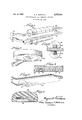
- Figure 1 is a perspective view of a hairpin coil embodying the invention
- Figure 2 is a transverse section through the coil showing a work piece associated therewith;
- Figure 3 is a perspective view of a pancake coil
- Figure 4 is a transverse section through the coil of Figure 3;
- Figure 5 is a perspective view of a single turn bus coil
- Figure 6 is a transverse section through the coil of Figure 5.
- the invention is applied to a conventional hairpin coil having tubular straight conducting portions 10 and 11 spaced parallel to each other and connected at one end by an quency current on the order of kc. or more.
- the conductors 10 and 11 are bent substantially at right angles and end in terminals 13 for connection to a source of high fre-
- the'entire coil is tubular and the terminals 13 are formed to circulate cooling fluid such as Water through the coil.
- a work piece as indicated at 14 in Figure 2, is passed between the straight conducting portions 10 and 11 in close proximity thereto.
- the high frequency current will induce heating current in the surface portions of the Work piece adjacent to the conductors to heat the work piece for tempering, annealing, or other purposes.
- the work piece may be a fiat plate which is positioned between the conductors, may be a tubularpiece which is rolled between the conductors for surface hardening, or may be any other type of work piece to be treated.
- core elements as shown at 15 are provided according to the present invention.
- Such core elements may be in the form of relatively short semi-cylindrical pieces having flat faces grooved to fit over the conductors as shown so that the flat faces of the core elements are substantially flush with the innerfaces of the conductors.
- any desired'riumber of core elements can be placed on the conductors in end-to-end relationship as seen in Figure l and for some purposes the core elements might be spaced to produce concentrated space heating spots.
- the core elements are formed of magnetic material so that they will confine the flux path around theconductors and will confine the path of the flux which intersects the work pieceto heat it. Therefore the stray fieldlosses are reduced and the area of the work piecewhichis to be heated is sharply. defined.
- the core elements were formed of conventional magnetic material, such as solid or laminated iron, the high frequency current would induce heating currents therein which would cause excessive heating of the core elements and would make them unuseable. According to the present invention this effect is eliminated by forming the core elements of fine particles of magnetic material suspended in a non-magnetic, non-conducting material.
- the particles of magnetic material are iron filings or iron dust, although any metal particles having good magnetic properties can be used.
- These particles are mixed with a non-conducting material, such as a plastic material, porcelain, or the like, which is then molded to the desired shape so that the particles are held in solid suspension therein in spaced relationship.
- the core material Due to the heating of the core material by proximity to the heated work piece, it is preferred to use a non-conducting material such as porcelain which will withstand relatively high temperatures without damage. Since the metallic particles are spaced in the core elements, the core elements themselves are non-conducting so that no current will be induced therein by flow of heating current through the conductors. Therefore the core elements will remain relatively cool except for heating due to their proximity to the heated work piece and can be used indefinitely without damage.
- a non-conducting material such as porcelain which will withstand relatively high temperatures without damage. Since the metallic particles are spaced in the core elements, the core elements themselves are non-conducting so that no current will be induced therein by flow of heating current through the conductors. Therefore the core elements will remain relatively cool except for heating due to their proximity to the heated work piece and can be used indefinitely without damage.
- the magnetic particles in the core elements must be of a fineness such that they will not be heated by the effect of the induced flux on the individual particles.
- the particles For high frequency heating current as contemplated herein having a frequency of 100 kc. or more, the particles must be on the order of microns or less in size to prevent this heating effect.
- the particles For still higher frequencies, on the order of 400 kc., the particles should be 5 microns or less in size.
- the size of the magnetic particles must be further reduced in order to avoid heating of the core elements. With core elements formed in this manner substantially no internal heating in the cores occurs and the core elements can be used over a substantially indefinite period without damage.
- FIGs 3 and 4 illustrate application of the principles of the invention to a pancake coil as used for surface heating.
- This coil is made up of a conducting tube 16 bent into an annulus and having terminals 17 projecting therefrom for connection to a source of heating current and for circulation of cooling fluid therethrough.
- the coil 16 is secured as by welding or brazing to a flat annular strip 18 which is separated between the terminals 17 to provide a greater conducting surface.
- the coil and strip 18 are received in an annular groove in a flat circular core element 19 which is formed of the same material as the core elements of Figures 1 and 2.
- the core element 19 confines the flux developed by the annular coil closely to a path around the conductors and between the annular edge and the center portion of the core element to confine the heating effect to the desired area.
- FIGS 5 and 6 illustrate application of the invention to a single turn bus coil for proximity heating.
- this coil is formed by a substantially rectangular elongated box 21 formed of conducting material connected at its ends to tubular terminals 22.
- the box 21 fits into an elongated groove in a core element 23 which is formed of the same material as the core elements 15 of Figure 1.
- the exposed face of the box 21 it to a source of current having a frequency on the order of at least kilocycles, and a core element partially encircling the conductor and having a smooth face substantially flush with one side of the conductor and at which side the conductor is exposed for positioning of a work piece close to the conductor and the core element, the core element being formed of fine particles of magnetic material suspended in spaced relationship in nonconducting material.
- a high frequency heating coil comprising an electrical conductor, terminals on the conductor to connect it to a source of high frequency heating current, and a core formed of a plurality of core elements, each core element having a smooth surface formed with a groove therein in which the conductor fits and the core elements being assembled end to end on the conductor, the core element being formed of particles of ferrous magnetic material of a size not over about ten microns suspended in spaced relationship in non-conducting material.
- a high frequency heating coil comprising an electrical conductor having an elongated substantially straight portion, terminals on the conductor to connect it to a source of high frequency heating current, and a core comprising a plurality of core elements each formed with a flat face having a groove therein in which the straight portion of the conductor fits, the core elements being assembled end to end on the straight portion of the conductor, each core element being formed of particles of magnetic material of a size not over about ten microns suspended in spaced relationship in non-conducting material.
Description
Jan. 8, 1957 H. c. DUSTMAN 2,777,041
HIGH FREQUENCY HEAT TREATING APPARATUS Filed May 21, 1955 IN V EN TOR.
mrz adm ATTORNEYS.
United States Patent HIGH FREQUENCY HEAT TREATING APPARATUS Herman C. Dustman, Northbrook, Ill., assignor to Lindberg Engineering Company, Chicago, 111., a corporation of Illinois Application May 21, 1953, Serial No. 356,359
3 Claims. (Cl. 21910.79)
to objects to be heated to induce heating current therein.
For effective operation it is desirable to confine the flux developed by passage of current through the conducting portion of the coil as closely as possible to the work so that stray field losses will be minimized and heating of the work will be confined to the desired areas.
It is impossible to use conventional solid or laminated core material for this purpose with currenbwhose frequency is in excess of about 50 kc. due to excessive heatingof .the core itself. In the high frequency rangeof 100 kc. and over, whichrange is referred to herein by the term high frequency, it has heretofore been impossible to confine the flux with the result that stray field losses occur and difficulty has been encountered in confining heating of the work pieces to the desired areas.
It is one of the objects of the present invention to provide a high frequency heat treating apparatus in which a core element is provided associated with the coil -tov confine the flux to the desired path and which is so constructed that it will not be heated by the flux.
It is a specific object of the invention to provide a high frequency heat treating, apparatus inwhich the coil conductor has associated therewith a coreelement formed of fine particles of magnetic material suspended in spaced relationship in non-conducting material. Such core elements are non-conducting and therefore will not be heated by induced current while serving to confine the flux substantially to the desired path.
Other objects relate to the provision of high frequency heat treating apparatus including coils and core elements specially shaped and associated to accommodate special heating problems.
The above and other objects and features of the invention will be more readily apparent from the following description when read in connection with the accompanying drawing, in which:
Figure 1 is a perspective view of a hairpin coil embodying the invention;
Figure 2 is a transverse section through the coil showing a work piece associated therewith;
Figure 3 is a perspective view of a pancake coil;
Figure 4 is a transverse section through the coil of Figure 3;
Figure 5 is a perspective view of a single turn bus coil; and
Figure 6 is a transverse section through the coil of Figure 5.
In the construction shown in Figures 1 and 2 the invention is applied to a conventional hairpin coil having tubular straight conducting portions 10 and 11 spaced parallel to each other and connected at one end by an quency current on the order of kc. or more.
Fee
offset loop 12. At the opposite ends the conductors 10 and 11 are bent substantially at right angles and end in terminals 13 for connection to a source of high fre- Preferably the'entire coil is tubular and the terminals 13 are formed to circulate cooling fluid such as Water through the coil.
In using a hairpin coil of the type shown, a work piece, as indicated at 14 in Figure 2, is passed between the straight conducting portions 10 and 11 in close proximity thereto. The high frequency current will induce heating current in the surface portions of the Work piece adjacent to the conductors to heat the work piece for tempering, annealing, or other purposes. It will be understood that the work piece may be a fiat plate which is positioned between the conductors, may be a tubularpiece which is rolled between the conductors for surface hardening, or may be any other type of work piece to be treated.
Inoperation of the apparatus flow of the high frequency current through the conductors produces a magnetic field around the conductors which penetrates the Work piece to induce heating'current therein. In the conventional high'frequency heat treating apparatus the magnetic field around the conductors is not confined 'so that substantially stray field'losses are encountered and so that heating of the workpiece is not sharply confined to the desired areas.
To reduce the stray field losses and to confine the heating effect on the work piece more sharply, core elements as shown at 15 are provided according to the present invention. Such core elements may be in the form of relatively short semi-cylindrical pieces having flat faces grooved to fit over the conductors as shown so that the flat faces of the core elements are substantially flush with the innerfaces of the conductors. With this construction any desired'riumber of core elements can be placed on the conductors in end-to-end relationship as seen in Figure l and for some purposes the core elements might be spaced to produce concentrated space heating spots. In any event, the core elements are formed of magnetic material so that they will confine the flux path around theconductors and will confine the path of the flux which intersects the work pieceto heat it. Therefore the stray fieldlosses are reduced and the area of the work piecewhichis to be heated is sharply. defined.
If the core elements were formed of conventional magnetic material, such as solid or laminated iron, the high frequency current would induce heating currents therein which would cause excessive heating of the core elements and would make them unuseable. According to the present invention this effect is eliminated by forming the core elements of fine particles of magnetic material suspended in a non-magnetic, non-conducting material. Preferably the particles of magnetic material are iron filings or iron dust, although any metal particles having good magnetic properties can be used. These particles are mixed with a non-conducting material, such as a plastic material, porcelain, or the like, which is then molded to the desired shape so that the particles are held in solid suspension therein in spaced relationship. Due to the heating of the core material by proximity to the heated work piece, it is preferred to use a non-conducting material such as porcelain which will withstand relatively high temperatures without damage. Since the metallic particles are spaced in the core elements, the core elements themselves are non-conducting so that no current will be induced therein by flow of heating current through the conductors. Therefore the core elements will remain relatively cool except for heating due to their proximity to the heated work piece and can be used indefinitely without damage.
I have found that the magnetic particles in the core elements must be of a fineness such that they will not be heated by the effect of the induced flux on the individual particles. For high frequency heating current as contemplated herein having a frequency of 100 kc. or more, the particles must be on the order of microns or less in size to prevent this heating effect. For still higher frequencies, on the order of 400 kc., the particles should be 5 microns or less in size. As the frequency is increased the size of the magnetic particles must be further reduced in order to avoid heating of the core elements. With core elements formed in this manner substantially no internal heating in the cores occurs and the core elements can be used over a substantially indefinite period without damage.
Figures 3 and 4 illustrate application of the principles of the invention to a pancake coil as used for surface heating. This coil is made up of a conducting tube 16 bent into an annulus and having terminals 17 projecting therefrom for connection to a source of heating current and for circulation of cooling fluid therethrough. Preferably the coil 16 is secured as by welding or brazing to a flat annular strip 18 which is separated between the terminals 17 to provide a greater conducting surface. The coil and strip 18 are received in an annular groove in a flat circular core element 19 which is formed of the same material as the core elements of Figures 1 and 2.
In using this construction the core element 19 confines the flux developed by the annular coil closely to a path around the conductors and between the annular edge and the center portion of the core element to confine the heating effect to the desired area.
Figures 5 and 6 illustrate application of the invention to a single turn bus coil for proximity heating. As shown, this coil is formed by a substantially rectangular elongated box 21 formed of conducting material connected at its ends to tubular terminals 22. The box 21 fits into an elongated groove in a core element 23 which is formed of the same material as the core elements 15 of Figure 1.
In using this construction the exposed face of the box 21 it to a source of current having a frequency on the order of at least kilocycles, and a core element partially encircling the conductor and having a smooth face substantially flush with one side of the conductor and at which side the conductor is exposed for positioning of a work piece close to the conductor and the core element, the core element being formed of fine particles of magnetic material suspended in spaced relationship in nonconducting material.
2. A high frequency heating coil comprising an electrical conductor, terminals on the conductor to connect it to a source of high frequency heating current, and a core formed of a plurality of core elements, each core element having a smooth surface formed with a groove therein in which the conductor fits and the core elements being assembled end to end on the conductor, the core element being formed of particles of ferrous magnetic material of a size not over about ten microns suspended in spaced relationship in non-conducting material.
3. A high frequency heating coil comprising an electrical conductor having an elongated substantially straight portion, terminals on the conductor to connect it to a source of high frequency heating current, and a core comprising a plurality of core elements each formed with a flat face having a groove therein in which the straight portion of the conductor fits, the core elements being assembled end to end on the straight portion of the conductor, each core element being formed of particles of magnetic material of a size not over about ten microns suspended in spaced relationship in non-conducting material.
References Cited in the file of this patent UNITED STATES PATENTS 1,981,629 Northrup Nov. 20, 1934 2,167,798 Denneen et a1. Aug. 1, 1939 2,226,871 Nicholas Dec. 31, 1940 2,240,494 Denneen et al. May 6, 1941 2,493,771 Marquardt et al. Jan. 10, 1950 2,493,950 Dow et a1 Jan. 10, 1950 2,623,081 Schorg Dec. 23, 1952 2,628,104 Shardlow Feb. 10, 1953 2,654,019 Body Sept. 29, 1953 2,671,846 Body Mar. 9, 1954 FOREIGN PATENTS 635,421 Great Britain Apr. 12, 1950 980,873 France May 18, 1951
Priority Applications (1)
| Application Number | Priority Date | Filing Date | Title |
|---|---|---|---|
| US356359A US2777041A (en) | 1953-05-21 | 1953-05-21 | High frequency heat treating apparatus |
Applications Claiming Priority (1)
| Application Number | Priority Date | Filing Date | Title |
|---|---|---|---|
| US356359A US2777041A (en) | 1953-05-21 | 1953-05-21 | High frequency heat treating apparatus |
Publications (1)
| Publication Number | Publication Date |
|---|---|
| US2777041A true US2777041A (en) | 1957-01-08 |
Family
ID=23401149
Family Applications (1)
| Application Number | Title | Priority Date | Filing Date |
|---|---|---|---|
| US356359A Expired - Lifetime US2777041A (en) | 1953-05-21 | 1953-05-21 | High frequency heat treating apparatus |
Country Status (1)
| Country | Link |
|---|---|
| US (1) | US2777041A (en) |
Cited By (17)
| Publication number | Priority date | Publication date | Assignee | Title |
|---|---|---|---|---|
| US3041434A (en) * | 1958-09-19 | 1962-06-26 | Deutsche Edelstahlwerke Ag | Method of and apparatus for inductively heating metal |
| US3119917A (en) * | 1961-01-04 | 1964-01-28 | United States Steel Corp | Induction heating device |
| US3242299A (en) * | 1963-10-17 | 1966-03-22 | Ohio Crankshaft Co | Inductor for induction heating apparatus |
| US3535481A (en) * | 1969-03-24 | 1970-10-20 | Plastics Eng Co | High frequency induction heating of semiconductive plastics |
| US3846609A (en) * | 1973-11-29 | 1974-11-05 | Park Ohio Industries Inc | Inductor for inductively heating elongated rotating workpiece |
| US3934115A (en) * | 1973-09-25 | 1976-01-20 | Peterson Gerald H | Method and apparatus for electric singe cutting |
| US4104498A (en) * | 1976-06-28 | 1978-08-01 | The Continental Group, Inc. | Apparatus for and method of induction heating of metal plates with holes |
| US4431891A (en) * | 1979-06-05 | 1984-02-14 | Siemens-Albis Ag | Arrangement for making contact between the conductor tracks of printed circuit boards with contact pins |
| US4527032A (en) * | 1982-11-08 | 1985-07-02 | Armco Inc. | Radio frequency induction heating device |
| EP0223517A2 (en) * | 1985-11-12 | 1987-05-27 | Continental Holdings Inc. | Induction heating unit for heat bonding a lid having a metallic layer to a container |
| US4698473A (en) * | 1986-05-02 | 1987-10-06 | General Motors Corporation | Refractory metal-lined induction coil |
| WO1997014547A1 (en) * | 1995-10-17 | 1997-04-24 | Tetra Laval Holdings & Finance S.A. | Inductor |
| US6153865A (en) * | 1997-10-29 | 2000-11-28 | Contour Hardening, Inc. | Induction hardening apparatus for a crankshaft |
| US6725630B2 (en) * | 2001-11-15 | 2004-04-27 | Sonoco Development, Inc. | Method for induction sealing a plastic part to a composite container |
| US20110084063A1 (en) * | 2009-10-02 | 2011-04-14 | Bollman John C | Arrangement and method for powering inductors for induction hardening |
| US20120255945A1 (en) * | 2011-04-05 | 2012-10-11 | Dey Subir K | Induction Seal Coil and Method |
| US20140007428A1 (en) * | 2010-12-15 | 2014-01-09 | Mahle International Gmbh | Heating device |
Citations (12)
| Publication number | Priority date | Publication date | Assignee | Title |
|---|---|---|---|---|
| US1981629A (en) * | 1930-10-07 | 1934-11-20 | Ajax Electrothermic Corp | Method and apparatus for inductive heating |
| US2167798A (en) * | 1935-08-19 | 1939-08-01 | Ohio Crankshaft Co | Apparatus for heat treating gears and the like |
| US2226871A (en) * | 1938-04-09 | 1940-12-31 | Hall Printing Co W F | Apparatus for drying |
| US2240494A (en) * | 1934-03-29 | 1941-05-06 | Ohio Crankshaft Co | Method of heat treating |
| US2493950A (en) * | 1944-12-01 | 1950-01-10 | Gen Motors Corp | High-frequency inductive welding apparatus |
| US2493771A (en) * | 1946-04-24 | 1950-01-10 | Ohio Crankshaft Co | Method of and apparatus for induction heating of small areas |
| GB635421A (en) * | 1948-04-06 | 1950-04-12 | Philips Nv | Improvements in or relating to high frequency induction heating apparatus |
| FR980873A (en) * | 1948-12-23 | 1951-05-18 | Csf | Improvements to high frequency induction heaters |
| US2623081A (en) * | 1948-12-14 | 1952-12-23 | Schorg Carl Christian | Induction coil mounting |
| US2628104A (en) * | 1950-03-31 | 1953-02-10 | Rca Corp | Induction heating of recording styli |
| US2654019A (en) * | 1950-10-06 | 1953-09-29 | Ohio Crankshaft Co | High-frequency induction-heating apparatus |
| US2671846A (en) * | 1950-02-28 | 1954-03-09 | Ohio Crankshaft Co | Means for inductively heating narrow elongated portions of cylindrical bodies |
-
1953
- 1953-05-21 US US356359A patent/US2777041A/en not_active Expired - Lifetime
Patent Citations (12)
| Publication number | Priority date | Publication date | Assignee | Title |
|---|---|---|---|---|
| US1981629A (en) * | 1930-10-07 | 1934-11-20 | Ajax Electrothermic Corp | Method and apparatus for inductive heating |
| US2240494A (en) * | 1934-03-29 | 1941-05-06 | Ohio Crankshaft Co | Method of heat treating |
| US2167798A (en) * | 1935-08-19 | 1939-08-01 | Ohio Crankshaft Co | Apparatus for heat treating gears and the like |
| US2226871A (en) * | 1938-04-09 | 1940-12-31 | Hall Printing Co W F | Apparatus for drying |
| US2493950A (en) * | 1944-12-01 | 1950-01-10 | Gen Motors Corp | High-frequency inductive welding apparatus |
| US2493771A (en) * | 1946-04-24 | 1950-01-10 | Ohio Crankshaft Co | Method of and apparatus for induction heating of small areas |
| GB635421A (en) * | 1948-04-06 | 1950-04-12 | Philips Nv | Improvements in or relating to high frequency induction heating apparatus |
| US2623081A (en) * | 1948-12-14 | 1952-12-23 | Schorg Carl Christian | Induction coil mounting |
| FR980873A (en) * | 1948-12-23 | 1951-05-18 | Csf | Improvements to high frequency induction heaters |
| US2671846A (en) * | 1950-02-28 | 1954-03-09 | Ohio Crankshaft Co | Means for inductively heating narrow elongated portions of cylindrical bodies |
| US2628104A (en) * | 1950-03-31 | 1953-02-10 | Rca Corp | Induction heating of recording styli |
| US2654019A (en) * | 1950-10-06 | 1953-09-29 | Ohio Crankshaft Co | High-frequency induction-heating apparatus |
Cited By (22)
| Publication number | Priority date | Publication date | Assignee | Title |
|---|---|---|---|---|
| US3041434A (en) * | 1958-09-19 | 1962-06-26 | Deutsche Edelstahlwerke Ag | Method of and apparatus for inductively heating metal |
| US3119917A (en) * | 1961-01-04 | 1964-01-28 | United States Steel Corp | Induction heating device |
| US3242299A (en) * | 1963-10-17 | 1966-03-22 | Ohio Crankshaft Co | Inductor for induction heating apparatus |
| US3535481A (en) * | 1969-03-24 | 1970-10-20 | Plastics Eng Co | High frequency induction heating of semiconductive plastics |
| US3934115A (en) * | 1973-09-25 | 1976-01-20 | Peterson Gerald H | Method and apparatus for electric singe cutting |
| US3846609A (en) * | 1973-11-29 | 1974-11-05 | Park Ohio Industries Inc | Inductor for inductively heating elongated rotating workpiece |
| US4104498A (en) * | 1976-06-28 | 1978-08-01 | The Continental Group, Inc. | Apparatus for and method of induction heating of metal plates with holes |
| US4431891A (en) * | 1979-06-05 | 1984-02-14 | Siemens-Albis Ag | Arrangement for making contact between the conductor tracks of printed circuit boards with contact pins |
| US4527032A (en) * | 1982-11-08 | 1985-07-02 | Armco Inc. | Radio frequency induction heating device |
| EP0223517A3 (en) * | 1985-11-12 | 1988-09-14 | Continental Can Company, Inc. | Induction heating unit for heat bonding a lid having a metallic layer to a container |
| EP0223517A2 (en) * | 1985-11-12 | 1987-05-27 | Continental Holdings Inc. | Induction heating unit for heat bonding a lid having a metallic layer to a container |
| US4698473A (en) * | 1986-05-02 | 1987-10-06 | General Motors Corporation | Refractory metal-lined induction coil |
| WO1997014547A1 (en) * | 1995-10-17 | 1997-04-24 | Tetra Laval Holdings & Finance S.A. | Inductor |
| AU702810B2 (en) * | 1995-10-17 | 1999-03-04 | Tetra Laval Holdings & Finance Sa | Inductor |
| US5968399A (en) * | 1995-10-17 | 1999-10-19 | Tetra Laval Holdings & Finance, S.A. | Inductor for induction sealing of packing material |
| US6153865A (en) * | 1997-10-29 | 2000-11-28 | Contour Hardening, Inc. | Induction hardening apparatus for a crankshaft |
| US6725630B2 (en) * | 2001-11-15 | 2004-04-27 | Sonoco Development, Inc. | Method for induction sealing a plastic part to a composite container |
| US20110084063A1 (en) * | 2009-10-02 | 2011-04-14 | Bollman John C | Arrangement and method for powering inductors for induction hardening |
| US8716636B2 (en) | 2009-10-02 | 2014-05-06 | John C. Bollman | Arrangement and method for powering inductors for induction hardening |
| US20140007428A1 (en) * | 2010-12-15 | 2014-01-09 | Mahle International Gmbh | Heating device |
| US9426847B2 (en) * | 2010-12-15 | 2016-08-23 | Mahle International Gmbh | Heating device |
| US20120255945A1 (en) * | 2011-04-05 | 2012-10-11 | Dey Subir K | Induction Seal Coil and Method |
Similar Documents
| Publication | Publication Date | Title |
|---|---|---|
| US2777041A (en) | High frequency heat treating apparatus | |
| US3142029A (en) | Shielding of foil wound electrical apparatus | |
| JP3181620B2 (en) | Electromagnetic device for heating metal elements | |
| US5844213A (en) | Induction heating coil assembly for prevention of circulating currents in induction heating lines for continuous-cast products | |
| US2810053A (en) | High frequency inductor for small diameter holes | |
| US3242299A (en) | Inductor for induction heating apparatus | |
| US2702004A (en) | Linear polyphase electromagnetic pump | |
| US2223970A (en) | Electric induction heating apparatus | |
| US3755644A (en) | High frequency induction heating apparatus | |
| US2005901A (en) | Induction sheet heater | |
| US2385031A (en) | Multiple-channel inductive heating apparatus | |
| US3121780A (en) | Inductor for heating a channel member | |
| US2427485A (en) | Electric induction furnace for continuously heating metal strip | |
| US2655589A (en) | High-frequency inductor | |
| US3413579A (en) | Magnetic field assembly for electro-mechanical transducers | |
| JPS57149616A (en) | Heat roll device | |
| US2513376A (en) | Induction heating coil | |
| US2879366A (en) | Electrical conductor for induction heating coils | |
| US2417029A (en) | Electric induction heating apparatus for continuously heating a plurality of metal strips | |
| GB2121260A (en) | Transverse flux induction heater | |
| US2832876A (en) | Inductor arrangement for induction heating | |
| JP2003187950A (en) | Single-turn induction heating coil | |
| JPS57205766A (en) | Induction heating and fixing roller | |
| JPS6139712B2 (en) | ||
| JPS6035985Y2 (en) | induction heating device |