US2840407A - Latch - Google Patents
Latch Download PDFInfo
- Publication number
- US2840407A US2840407A US572399A US57239956A US2840407A US 2840407 A US2840407 A US 2840407A US 572399 A US572399 A US 572399A US 57239956 A US57239956 A US 57239956A US 2840407 A US2840407 A US 2840407A
- Authority
- US
- United States
- Prior art keywords
- bolt
- slot
- housing
- wall
- spring
- Prior art date
- Legal status (The legal status is an assumption and is not a legal conclusion. Google has not performed a legal analysis and makes no representation as to the accuracy of the status listed.)
- Expired - Lifetime
Links
Images
Classifications
-
- E—FIXED CONSTRUCTIONS
- E05—LOCKS; KEYS; WINDOW OR DOOR FITTINGS; SAFES
- E05C—BOLTS OR FASTENING DEVICES FOR WINGS, SPECIALLY FOR DOORS OR WINDOWS
- E05C1/00—Fastening devices with bolts moving rectilinearly
- E05C1/08—Fastening devices with bolts moving rectilinearly with latching action
- E05C1/12—Fastening devices with bolts moving rectilinearly with latching action with operating handle or equivalent member moving otherwise than rigidly with the latch
- E05C1/14—Fastening devices with bolts moving rectilinearly with latching action with operating handle or equivalent member moving otherwise than rigidly with the latch the handle or member moving essentially towards or away from the plane of the wing or frame
- E05C1/145—Fastening devices with bolts moving rectilinearly with latching action with operating handle or equivalent member moving otherwise than rigidly with the latch the handle or member moving essentially towards or away from the plane of the wing or frame flush
-
- Y—GENERAL TAGGING OF NEW TECHNOLOGICAL DEVELOPMENTS; GENERAL TAGGING OF CROSS-SECTIONAL TECHNOLOGIES SPANNING OVER SEVERAL SECTIONS OF THE IPC; TECHNICAL SUBJECTS COVERED BY FORMER USPC CROSS-REFERENCE ART COLLECTIONS [XRACs] AND DIGESTS
- Y10—TECHNICAL SUBJECTS COVERED BY FORMER USPC
- Y10S—TECHNICAL SUBJECTS COVERED BY FORMER USPC CROSS-REFERENCE ART COLLECTIONS [XRACs] AND DIGESTS
- Y10S292/00—Closure fasteners
- Y10S292/31—Lever operator, flush
-
- Y—GENERAL TAGGING OF NEW TECHNOLOGICAL DEVELOPMENTS; GENERAL TAGGING OF CROSS-SECTIONAL TECHNOLOGIES SPANNING OVER SEVERAL SECTIONS OF THE IPC; TECHNICAL SUBJECTS COVERED BY FORMER USPC CROSS-REFERENCE ART COLLECTIONS [XRACs] AND DIGESTS
- Y10—TECHNICAL SUBJECTS COVERED BY FORMER USPC
- Y10T—TECHNICAL SUBJECTS COVERED BY FORMER US CLASSIFICATION
- Y10T292/00—Closure fasteners
- Y10T292/08—Bolts
- Y10T292/096—Sliding
- Y10T292/0969—Spring projected
- Y10T292/097—Operating means
- Y10T292/0977—Cam
-
- Y—GENERAL TAGGING OF NEW TECHNOLOGICAL DEVELOPMENTS; GENERAL TAGGING OF CROSS-SECTIONAL TECHNOLOGIES SPANNING OVER SEVERAL SECTIONS OF THE IPC; TECHNICAL SUBJECTS COVERED BY FORMER USPC CROSS-REFERENCE ART COLLECTIONS [XRACs] AND DIGESTS
- Y10—TECHNICAL SUBJECTS COVERED BY FORMER USPC
- Y10T—TECHNICAL SUBJECTS COVERED BY FORMER US CLASSIFICATION
- Y10T292/00—Closure fasteners
- Y10T292/57—Operators with knobs or handles
Landscapes
- Engineering & Computer Science (AREA)
- Mechanical Engineering (AREA)
- Chairs Characterized By Structure (AREA)
Description
`lune 24, 1958 R. N. SELLON, JR
LATCH Filed March 1.9, 1956 IN VEN TOR. E@ wwe/va /V 551. 4 0N, Je.
United States Patent 2,849,407 LATCH Application March 19,1956, Serial No. 572,399 Claims. (Cl. 292-169) This invention relatesy to a latch.
It is the object of the invention to provide a simplied andvmore smoothly operable construction. The paddle lever lits into a recessed housing andfis pivotedupon a pintle which spans the recess. The housing has a slot in its back wall a portion of the material from which is thrust rearwardly in the form of a tongue to provide a seat anchorage for a tension spring.
A bolt slides on the rear face of `the back wall of the housing and has a forwardly embossed portion Vwhich lits into the slot of the housing yto guide the bolt in the course of its reciprocation. The spring anchorage tongue of the housing projects 'through an aperture in `the bolt. The bolt has the form of a channel in which its tension spring is disposed, the endv of the spring other than, that connected with the housing being connected with another tongue whichis a part of the bolt.
In order to hold the bolt to the housing and at the same time to transmit motion ofl the paddleV lever thereto, a plate is spot welded Aor otherwise `connectedto the torwardly embossedportion of the bolt and is provided with upstandingA ears engaged, bythe closedffront end of the paddle lever. Thus, the raising of :the paddle lever cams these uptanding ears in abolt-retraeting direction against tension of the spring. Upon release of the paddle lever, the spring not only returns the bolt vbut the lever to the original position.
In the drawings: Y
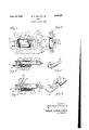
Fig. l is a view in front elevation of a paddle latch organization as assembled on the face of a door which is fragmentarily illustrated.
Fig. 2 is a view of the paddle latch assembly in rear elevation, the door being shown in section.
Fig. 3 is a detail View taken in section on line 3 3 of Fig. l.
Fig. 4 is a view similar to Fig. 3 showing the paddle lever raised to retract the bolt.
Fig. 5 is a detail view in perspective of the plate which contains the bolt to the housing.
Fig. 6 is a fragmentary detail View of the bolt in perspective, portions being broken away to show it in cross section.
The housing 7 is pan-shaped and is placed in openin 8 in door 9 in the usual way. lts rear wall 10 is provided with a slot 11 extending longitudinally of the housing.
The bolt 12 is channel-shaped, having sides 13 and 14 which are beveled at 15.` The web of the channelledbolt 12 spans slot 11 of the housing and has an intermediate outwardly embossed area at 16 which is elongated longi. tudinally of the bolt and corresponds in width to the slot 11. The embossed portion 16 of the bolt is less long than the slot to permit of movement of the bolt between its advanced and retracted positions, the embossed portion 16 of the bolt bearing on the housing at the sides of the slot and serving to guide the bolt with respect to the housing.
A tongue 17 formed of the material of the housing and sono? 2. extending rearwardly from the forward end ofslot 11 provides an anchorage for the eye 18 at one end of tension spring 20. The tongue 17 extends through anopening 19 in the bolt, the spring being housed withinthe bolt channel. The other end ofthe spring is anchored to tongue 21 of the bolt 12. Y
In order to hold the bolt in place for reciprocation. of its embossed portion 16 in the slot 11, a retaining and carrying plate 25 is disposed within the pan-shaped housing 7 to span the slot 11 and to slide longitudinally of the rear wall 10 of the housing. lThe plate 25 is connected with the embossed'portion 16 of the boltby spot welding 27 or otherwise. This connection ismadethrough the slot 11 to hold the bolt in sliding engagement with the outside of wall 26. Slide plate 25 reciprocaes with the vbolt in bearing engagement with the inner surface of that Wall.
The plate 25 has upstanding laterally spaced ears 23 which are engaged by the forward. ends 29 of paddle lever 30. The paddle lever is pivoted on a pintle 31 which spans the pan-shaped housing 7. The pintle passes through the side flanges 32 of the paddle lever which are connected with the end wall 29 and the top web 33 thereof. The extreme rear portion 34 of the top web 33 may be turned upwardly to receive the operators ngers if desired. l
The `device is practically rattleffree, since the forward Y ends of the cam lianges 23 are engaged under tension of `spring 20 at all times with the forward wall 29 of the ,paddle lever.
Vlever to cam the anges 28 rearwardlyfthus imparting rearward movement to bolt 12 in opposition to the tension spring 20. Fig. 4 shows the bolt in its fully retracted position from which it is returned by spring 2t? to the position of Fig. 3 as soon as thrust from the paddle lever is released.
I claim:
l. In a latch, the combination with a mounting member having a slotted wall, of a bolt wider than the slot in said wall and reciprocable on the outer face of the wall and provided with an embossed portion narrower than the bolt and corresponding in width to the slot of said member and disposed therein to guide the bolt in the course ot' its reciprocation with respect to the member, a slide wider than the bolt and fastened to the embossed portion of the bolt and spanning the slot along the inner face of the wall to retain the bolt on said wall, and means for reciprocating the bolt.
2. In a latch, the combination with a mounting member having a slotted wall, Vof a bolt reciprocable on the outer face of the wall and provided with an embossed portion corresponding in width to the slot of said member and disposed therein to guide the bolt in the course of its reciprocation respecting the member, means for retaining the bolt to the wall of the member, and means for reciprocating the bolt, the means for retaining the bolt comprising a plate having bearing contact with the inner Vface of the housing and spanning the slot therein, said plate having connection with the embossed portion of the bolt.
3. The device of claim 2 in which the means for reciprocating the bolt comprises a spring biasing the bolt toward an extended position and a lever having camming engagement with said plate and pivoted to the member for retracting the bolt.
Patented June 24, 1958 n 4. In a device of the character described, the combination with a mounting plate provided with a longitudinal slot, of a channel-shaped bolt comprisinga web and side anges, the web being in bearing `engagement with the mounting plate beside the slot and having an embossed portionsubstantially corresponding in width to theslot and extending intothe slot to bear on the marginsof` the mounting plate at opposite sides of the slot for the guidance of the bolt,` the `slot being longer than the embossed portion of the bolt web whereby to accommodate reciprocation of the bolt respecting the mounting plate, a spring housed within thechannel of the bolt,Y the mounting plate and bolt" being provided with spring anchorages with which theends of the spring are engaged, and a slide `spanning the slot of the mounting plate and connected with the embossed portion of the bolt web for maintaining bination for association with' a slotted mounting "plate,
the sub-combination comprising a bolt having an integral spanning the housing from one side wall to the other, a lever having a top web and side and end portions, the side portions being mounted on the pintle, a plate spanning the slot of the housing and provided with upstanding ear means disposed between the side portions of the lever and engaged bythe end portion thereof, and a bolt slidable upon the rear faceof the housing and spanning the slot of the housing, said `bolt having integral means extending through the housing slot and connected with said plate to receive motion therefrom, and a spring having anchoragesonthe housing of the bolt andV biasing the bolt in oppositionV to the displacement thereof eifected by engagement of the lever with said ear means.
9. The combination recited in claim 8 in which the bolt has the form of a channel with its web portion slidable on the rear face of the housing and ilanges projecting therefrom, the said spring being housed between said flanges. l
l0. In a device `of the character described vthe combination with `two relatively reciprocable members, one of which is provided with a wall having a slot, and the i other of which comprises spaced slides wider than the slot embossed portion substantially corresponding inwidth to the slot and of less width than the bolt theside surfaces of said embossed portion being facially continuous with the top oftsaid bolt to'engage the sides of the mounting plate at said slot, and a retaining slide in connection and Spanning the slot at opposite sides of the rst member,` said slides being connected through the slot by a boss substantially equal to the slot in width and of a length less than that of the slot, the boss being disposed in the slot in` bearing engagement with the margins of said wall of the tirst member at the opposite sides of the slot for guiding` relative reciprocation between said members, the Vsaid boss being integral with one of said members and having laterally unbroken facial continuity with said one member, whereby to provide a finished surface bearing on said margins of said slotted wall.
7. The sub-combination recited in claim in which the retaining slide has outstandingcam ange means.`
8. In a device of the character described, the combina- References Cited in the tile of this patent UNITED STATES PATENTS Tasch et a1 Sept. 18,
Priority Applications (1)
| Application Number | Priority Date | Filing Date | Title |
|---|---|---|---|
| US572399A US2840407A (en) | 1956-03-19 | 1956-03-19 | Latch |
Applications Claiming Priority (1)
| Application Number | Priority Date | Filing Date | Title |
|---|---|---|---|
| US572399A US2840407A (en) | 1956-03-19 | 1956-03-19 | Latch |
Publications (1)
| Publication Number | Publication Date |
|---|---|
| US2840407A true US2840407A (en) | 1958-06-24 |
Family
ID=24287633
Family Applications (1)
| Application Number | Title | Priority Date | Filing Date |
|---|---|---|---|
| US572399A Expired - Lifetime US2840407A (en) | 1956-03-19 | 1956-03-19 | Latch |
Country Status (1)
| Country | Link |
|---|---|
| US (1) | US2840407A (en) |
Cited By (11)
| Publication number | Priority date | Publication date | Assignee | Title |
|---|---|---|---|---|
| US4470624A (en) * | 1982-06-01 | 1984-09-11 | Southco, Inc. | Tool operated flush slam latch |
| US4838056A (en) * | 1984-04-18 | 1989-06-13 | The Eastern Company | Latch and lock assemblies with expansible latch elements |
| US4838054A (en) * | 1984-04-18 | 1989-06-13 | The Eastern Company | Latch and lock assemblies with lift and turn handles |
| US4841755A (en) * | 1984-04-18 | 1989-06-27 | The Eastern Company | Latch and lock assemblies with spring-biased slide bolts |
| US4850209A (en) * | 1986-04-28 | 1989-07-25 | The Eastern Company | Latch and lock housings, handles and mounting brackets |
| USD314131S (en) | 1989-07-24 | 1991-01-29 | The Eastern Company | Housings for latches and locks |
| US5046340A (en) * | 1984-04-18 | 1991-09-10 | The Eastern Company | Latch and lock assemblies with spring-biased pivot bolts |
| WO2000019050A1 (en) * | 1998-09-30 | 2000-04-06 | Southco, Inc. | Load floor slam-action pawl latch |
| US6109669A (en) * | 1998-09-30 | 2000-08-29 | Southco, Inc. | Load floor slam-action paw latch |
| US20040119294A1 (en) * | 2002-12-20 | 2004-06-24 | Yong Tai Loong (Pte) Ltd. | Locking mechanism |
| USD981819S1 (en) * | 2020-10-30 | 2023-03-28 | Zoox, Inc. | Vehicle with a door opening lever |
Citations (5)
| Publication number | Priority date | Publication date | Assignee | Title |
|---|---|---|---|---|
| US2236391A (en) * | 1940-04-03 | 1941-03-25 | Frederick R Zabel | Locking device |
| US2642300A (en) * | 1951-03-14 | 1953-06-16 | Eastern Malleable Iron Company | Flush type door lock |
| US2668076A (en) * | 1951-10-17 | 1954-02-02 | J H Holan Corp | Locking-bolt operating structure |
| US2746784A (en) * | 1953-10-30 | 1956-05-22 | Edward W Holritz | Latch |
| US2763503A (en) * | 1954-07-12 | 1956-09-18 | Mccabe Powers Auto Body Co | Door lock |
-
1956
- 1956-03-19 US US572399A patent/US2840407A/en not_active Expired - Lifetime
Patent Citations (5)
| Publication number | Priority date | Publication date | Assignee | Title |
|---|---|---|---|---|
| US2236391A (en) * | 1940-04-03 | 1941-03-25 | Frederick R Zabel | Locking device |
| US2642300A (en) * | 1951-03-14 | 1953-06-16 | Eastern Malleable Iron Company | Flush type door lock |
| US2668076A (en) * | 1951-10-17 | 1954-02-02 | J H Holan Corp | Locking-bolt operating structure |
| US2746784A (en) * | 1953-10-30 | 1956-05-22 | Edward W Holritz | Latch |
| US2763503A (en) * | 1954-07-12 | 1956-09-18 | Mccabe Powers Auto Body Co | Door lock |
Cited By (13)
| Publication number | Priority date | Publication date | Assignee | Title |
|---|---|---|---|---|
| US4470624A (en) * | 1982-06-01 | 1984-09-11 | Southco, Inc. | Tool operated flush slam latch |
| US4969916A (en) * | 1984-04-18 | 1990-11-13 | The Eastern Company | Latch and lock assemblies with spring-biased pivot bolts |
| US4838054A (en) * | 1984-04-18 | 1989-06-13 | The Eastern Company | Latch and lock assemblies with lift and turn handles |
| US4841755A (en) * | 1984-04-18 | 1989-06-27 | The Eastern Company | Latch and lock assemblies with spring-biased slide bolts |
| US4838056A (en) * | 1984-04-18 | 1989-06-13 | The Eastern Company | Latch and lock assemblies with expansible latch elements |
| US5046340A (en) * | 1984-04-18 | 1991-09-10 | The Eastern Company | Latch and lock assemblies with spring-biased pivot bolts |
| US4850209A (en) * | 1986-04-28 | 1989-07-25 | The Eastern Company | Latch and lock housings, handles and mounting brackets |
| US4850208A (en) * | 1986-04-28 | 1989-07-25 | The Eastern Company | Latch and lock assemblies with spring-biased pivot bolts |
| USD314131S (en) | 1989-07-24 | 1991-01-29 | The Eastern Company | Housings for latches and locks |
| WO2000019050A1 (en) * | 1998-09-30 | 2000-04-06 | Southco, Inc. | Load floor slam-action pawl latch |
| US6109669A (en) * | 1998-09-30 | 2000-08-29 | Southco, Inc. | Load floor slam-action paw latch |
| US20040119294A1 (en) * | 2002-12-20 | 2004-06-24 | Yong Tai Loong (Pte) Ltd. | Locking mechanism |
| USD981819S1 (en) * | 2020-10-30 | 2023-03-28 | Zoox, Inc. | Vehicle with a door opening lever |
Similar Documents
| Publication | Publication Date | Title |
|---|---|---|
| US2840407A (en) | Latch | |
| US4153996A (en) | Coilable rule with combination blade lock and shock absorber mechanism | |
| US7201409B2 (en) | Retracting locking mechanism for operable unit in stop position | |
| US2642300A (en) | Flush type door lock | |
| US2805106A (en) | Double extension slides | |
| WO2007122831A1 (en) | Self-propelled forward movement mechanism of movable body, sliding door, and spacer device | |
| JP4291427B2 (en) | Sliding door structure and sliding door closing device | |
| JP5726556B2 (en) | Opening and closing body closing device | |
| DE3415613A1 (en) | CAMERA WITH BUILT-IN FLASH DEVICE | |
| CN107542326B (en) | Sliding key | |
| US2078651A (en) | Belt buckle | |
| US5071180A (en) | Arresting device for a hinged component | |
| US4135434A (en) | Breechblock for an automatic firing weapon | |
| US4413489A (en) | Furniture lock | |
| US3441269A (en) | Latch bolt mechanism | |
| US4101161A (en) | Opening roof assemblies for vehicles | |
| EP1199428B1 (en) | Espagnolette locking device | |
| US4630365A (en) | Blade replaceable type barber razor | |
| JP3925887B2 (en) | Drawer closing device | |
| JPH05133157A (en) | Sliding door | |
| JPH1130033A (en) | Scaffolding board | |
| JPH0941770A (en) | Window stay | |
| JP2018013011A (en) | Slide type automatic closing apparatus | |
| US5417253A (en) | Tool for binding an object by means of a strip | |
| US3777522A (en) | Closure for cylinder lock mechanism |