US2887599A - Electron acceleration tube - Google Patents
Electron acceleration tube Download PDFInfo
- Publication number
- US2887599A US2887599A US666110A US66611057A US2887599A US 2887599 A US2887599 A US 2887599A US 666110 A US666110 A US 666110A US 66611057 A US66611057 A US 66611057A US 2887599 A US2887599 A US 2887599A
- Authority
- US
- United States
- Prior art keywords
- electron
- cathode
- enclosure
- electrons
- extended
- Prior art date
- Legal status (The legal status is an assumption and is not a legal conclusion. Google has not performed a legal analysis and makes no representation as to the accuracy of the status listed.)
- Expired - Lifetime
Links
Images


Classifications
-
- H—ELECTRICITY
- H01—ELECTRIC ELEMENTS
- H01J—ELECTRIC DISCHARGE TUBES OR DISCHARGE LAMPS
- H01J33/00—Discharge tubes with provision for emergence of electrons or ions from the vessel; Lenard tubes
Definitions
- the invention relates to electron acceleration tubes, and in particular to a construction for electron acceleration tubes which has special utility for the radiation processing of thin. films at high speed, such as irradiating layers of paint on automobiles, irradiating layers of ink in magazine printing, etc.
- the acceleration tube of the invention requiresno scanning method to irradiate a substantial width and should be capable of handling output currents of atleast 20 milliamperes and output electron powers of. at least 10 kilowatts.
- the tube is totally enclosed in a grounded metal container which constitutes its own onvelope an-dis relatively compact. This type of construction would be suitable for voltages up to and in excess of 1 million volts; its probable voltageregion of use lies in the region from 200 kilovolts to 1,000"kilovolts.
- the invention comprehends an acceleration tube which consists basically of an extended high-voltage cathode structure within which an electron-emitting filament is positioned, a grounded metallic structurewhich encloses the vacuum and which has an extended thin window to permit electrons to emerge into air, and one or more equipotential shields maintained at intermediate voltages to divide the total potential difference between cathode and ahode in a regular fashion to avoid the total voltage eifect;
- an evacuated acceleration tube is enclosed within a grounded tank which is filled with insulating gas under pressure, and therefore the walls of the acceleration tube have to support the pressure difference.
- the grounded enclosure is entirely evacuated, there is no pressure diflerential within it, and so the insulating members of the acceleration tube need not be in contact with metal over so large an area as in the conventional high voltage accelerator.
- the metal parts of the device may be thinner, so that the high voltage terminal may be extruded and theintermediate electrodes may be sheet metal.
- the electron accelerating region does not itself contain any solid insulation, and the arrangement of metallic electrodes has many advantages in simplicity and compactness. Since the device employs vacuum insulation, one encounters the total voltage? effect.
- the power supply for this tube may be of any suitable type. This power source would supply both the power required to accelerate the electrons to high "energy and to heat the electron-emitting elements. There is no particular point in putting the high-voltage generator within this same structure, and accordingly high voltage power is introduced from any suitable high-voltage generator via a suitable cable. Alternatively), the high-voltage 2,887,599. Patented May 19, 1959 generator may be placed adjacent the evacuated structure so as to eliminate thefcable.
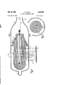
- Fig. l is a longitudinal central section through an electron acceleration tube embodying the invention.
- Fig. 2 is a section along the line 22 of Fig. 1;
- Fig. 3 is a longitudinal central section showing a modificationof the apparatus of Fig. 1.
- Fig. 4 is a view'along the line 44 of Fig. 3;
- Fig. 5 is a view similar to that of Fig. 4 but showing a modified arrangement of vthe cathode filaments;
- Fig. 6 is a view similar. to that of Fig. 2, but showing a modification in which two electron ports are provided;
- Fig. 7 is a longitudinal central section showing still another modification of the apparatus of Fig. 1;
- Fig. Si a section along the line 88-of Fig. 7.
- a grounded container 1 which may be of steel, is evacuated by any conventional vacuum pump and a high vacuum is maintained therein by any suitable device such as a barium getter ion pump 2.
- hire 3 is supported centrally within said grounded container 1 and is maintained at a high negative potential.
- Electrons are released from a filament 4 within the oathode structure 3 and are accelerated radially outward towards the grounded container 1.
- An electron window 5 forming part ofthe wall .of the container 1 permits the accelerated electrons to emerge from within the grounded container 1 into the atmosphere in the form of a sheetlike stream 6 and onto the thin film 7 which isto be irradiated and which is conveyed through the electron beam 6 by a conveyor belt 8 or other suitable support. Since the source of electrons is an extended line filament 4, the electrons are accelerated in sheet form, so that the electron window system for this type of tube is extended in at least one. dimension and is therefore able to handle a larger total electron current. If
- forced air cooling may be provided on the outside to further increase the current margin.
- the cathode'structure 3 is maintained at high voltage by a-voltage generator (not shown) which in general will be outside the'grounded container 1.
- the high voltage power is fed from the generator to the cathode structure I 3 by a suitable highvoltage cable 9 which may include a central high voltage conductor 10 enclosed in a grounded casing 11 and insulating therefrom by a gaseous or-liquid insulated medium, such as an insulating gas under 5 pressure.
- the casing 11 is connected to the grounded container 1 and the high voltage conductor 10 is connected to the high voltage cathode structure 3.
- the high voltage cable 9 may also serve to introduce electric power for heating the filament 4.
- the high voltage conductor l0 may comprise two wires both at high negative potential but between which a small potential difference is maintained and across which the filament 4 is connected.
- FIG. 1 An important part of this embodiment of the invention is the high voltage bushing 12 in the wall of the container 1; which separates the vacuum within the container 1 from the gaseous or liquid medium in the cable 9 and which insulates the high voltage parts of the apparatus from the grounded container l-and casing 11.
- This problem is a difficult one because the surface of the solid 1nsulat1on which is required for'mechanical support will not support as high a voltage gradient as vacuum or pressure insulation, so that the length of solid insulation intervening between the high voltage central electrode 7 and the grounded container must be greater than the corresponding length within the vacuum or within the cable.
- This difliculty is solved in a relatively straightforward and compact fashion in accordance with the invention by means of the apparatus shown in Figs. 1 and 3. Referring to Fig.
- the high voltage bushing 12 comprises alternating insulator rings 13 and annular electrodes 14.
- the insulating rings 13 are of diminishing diameter and are axially spaced from one another by the electrodes 14. In this way the insulating paths through the solid insulator and along its surface are rendered longer than the insulating path through the vacuum or the pressurized insulating medium.
- the rings 13 may be made of glass or porcelain or other appropriate insulator.
- the rings 13 may be of constant diameter, in which event it is necessary that the diameter of the grounded casing 11 be enlarged in the vicinity of the high voltage bushing 12.
- the evacuated region within the container 1 is subject to electrical breakdown produced by the total voltage effeet.
- one or more intermediate conductive shields 15 may be provided between the cathode structure 3 and the grounded container 1.
- Each of these shields 15 may conveniently be connected to and supported by one of the electrodes 14, and in general it will be necessary to have only as many electrodes 14 as there are intermediate shields, since the insulators 13 may be as thick as desired in the axial direction.
- the structural members must support high pressure against high vacuum, and so the metal members within the evacuated region may be relatively thin.
- the intermediate shields 15 may comprise sheet metal about A of an inch thick or possibly of an inch thick. Assuming that vacuum insulation can support 50 kilovolts across a quarter-inch gap, the embodiments of the invention shown in Figs. 1 through 3, in which the electrodes take the form of concentric circles, permit the overall diameter of a ZOO-kilovolt device to be as small as 6 inches if the total gap in the evacuated region is subdivided into 4 subgaps.
- each of the intermediate shields be provided with apertures 16 corresponding to the electron window to permit passage of the electron stream.
- the electron emitter within the cathode structure 3 releases electrons over an extended area.
- the electron emitter is a single filament 4 which may be made of tungsten, molybdenum, or other material.
- the location of the filament 4 with respect to the cathode struc ture 3 should preferably be such that the current in the electron beam be space-charge limited. This would have the effect of insuring that approximate uniformity exists in the current density along the extended beam relatively independent of local variations in the filament emission.
- the electron emitter may comprise a series of relatively short lengths 17 of such filaments positioned either in line with one another, as shown in Figs. 3 and 4. or so skewed with respect to each other that no gaps exist in the electron pattern which finally emerges from the tube, as shown in Fig. 5.
- the intermediate shields 15 would have multiple apertures 18, and the grounded container 1 would have multiple electron windows 19, the pattern whereof would correspond to that of the filament segments 17 as shown in Figs. 4 and 5.
- filament segments 17 are used, they are preferably connected in parallel so that the failure of one filament will not effect the entire radiation process.
- FIG. 6 A modification of the electron acceleration tube of Figs. 1 through 3 is shown in Fig. 6, wherein a tube is shown having two opposite ports or electron windows 20, 21, with the film 7 to be irradiated going by one port 20 and going back by the other 21.
- the electrodes are arranged concentrically.
- An alternative construction is shown in Figs. 7 and 8.
- the cathode structure 22 is supported upon a column comprising a series of extended electrodes 23 separated by one or more corresponding series of insulators 24.
- Preferably only four such series of insulators 24 are employed, one at each corner of the rectangular colum, in order to minimize the deleterious effect of radiation on the insulators 24.
- Intermediate shields 25 connected to the electrodes 23 extend around the cathode structure 22 so as to avoid the total voltage effect.
- the vacuum-insulated gap between the cathode structure 22 and the tank 26 may be as small as 3 inches, as in the corresponding gap of the apparatus of Fig. 1, but the length of the column must be 6 inches because of the solid insulation, which can support only about 30 kilovolts over a three-quarterinch gap. Assuming the cathode structure 22 to be 3 inches in height, the overall diameter of the device of Figs. 7 and 8 would be about one foot. Any of the embodiments of the invention shown in the drawings is especially adapted to very long electron sheets, and might provide a stream of 200-kilovolt electrons one yard in length at one milliampere per inch.
- the function of the subdivided high-voltage bushing 12 of Fig. l is performed by the solid insulation 27 in the cable 28.
- the length of the insulating path between the grounded tank 26, to which the outer casing 29 of the cable 28 is connected, and the high-voltage conductor 30 along the surface of the solid insulator 27 is increased by having the solid insulator 27 protrude into the evacuated region for some distance. This prevents fiashover along the surface of the solid insulation, which would otherwise occur at voltages much lower than the voltage at which breakdown through the solid insulation might occur.
- An acceleration tube capable of delivering simultaneously an electron beam of extended cross-section to the region outside said tube, comprising in combination: an evacuated metallic enclosure at ground potential, an elongated metallic cathode provided with an extended line source of electrons and maintained at high negative potential within said enclosure by an external power source, an electron-permeable anode electrode at ground potential adapted to accelerate in mutually parallel paths electrons emitted by said line source of electrons, and an extended electron window in the wall of said enclosure adapted to permit the emergence of the accelerated electrons out of said evacuated enclosure.
- An acceleration tube capable of delivering simultaneously an electron beam of extended cross-section to the region outside said tube, comprising in combination: an evacuated metallic enclosure at ground potential, an elongated metallic cathode provided with an extended line source of electrons and maintained at high negative potential within said enclosure by an external power source, an electron-permeable anode electrode at ground potential adapted to accelerate in mutually parallel paths electrons emitted by said line source of electrons, an extended electron window in the wall of said enclosure adapted to permit the emergence of the accelerated electrons out of said evacuated enclosure, and a metallic electrode between said cathode and said anode maintained at an intermediate potential and adapted to permit the passage of said electron beam and to divide the total voltage between cathode and anode.
- An acceleration tube capable of delivering simultaneously an electron beam of extended cross-section to the region outside said tube, comprising in combination: an evacuated metallic enclosure at ground potential, an elongated metallic cathode provided with an extended line source of electrons and maintained at high negative potential within said enclosure by an external power source an electron-permeable anode electrode at ground potential adapted to accelerate in mutually parallel paths electrons emitted by said line source of electrons, an extended electron window in the wall of said enclosure adapted to per mit the emergence of the accelerated electrons out of said evacuated enclosure, and a series of spaced metallic electrodes between said cathode and said anode maintained at progressively more negative potential the nearer their position to said cathode and adapted to assist the passage of said electron beam and to divide the total voltage between cathode and anode.
- An acceleration tube capable of delivering simultaneously an electron beam of extended cross-section to the region outside said tube, comprising in combination: an evacuated metallic enclosure at ground potential, an elongated metallic cathode provided with an extended line source of electrons and maintained at high negative potential within said enclosure by an external power source, a plurality of electron-permeable anode electrodes at ground potential adapted to accelerate, in a plurality-of azimuthially spaced streams each comprising mutually parallel paths, electrons emitted by said line source of electrons, a corresponding plurality of extended electron windows in the wall of said enclosure adapted to permit the emergence of the accelerated electrons out of said evacuated enclosure, and at least one metallic electrode between said cathode and said anode maintained at an intermediate potential and adapted to permit the passage of said plurality of azimuthially spaced streams and to divide the total voltage between cathode and anode.
- An acceleration tube capable of delivering simultaneously an electron beam of extended cross-section to the region outside said tube, comprising in combination:
- an evacuated metallic enclosure at ground potential an elongated metallic cathode provided with an extended line source of electrons and maintained at high negative potential within said enclosure by an external power source, an electron-permeable anode electrode at ground potential adapted to accelerate in mutually parallel paths electrons emitted by said line source of electrons, an extended electron window in the wall of said enclosure adapted to permit the emergence of the accelerated electrons out of said evacuated enclosure, and a high voltage bushing in the wall of said enclosure adapted to provide the mechanical support for said cathode in addition to introduceing the high voltage power.
- An acceleration tube capable of delivering simultaneously an electron beam of extended cross-section to the region outside said tube, comprising in combination: an evacuated metallic enclosure at ground potential, an elongated metallic cathode provided with an extended line source of electrons and maintained at high negative potential within said enclosure by an external power source which is enclosed within a second grounded enclosure containing an insulating gas under pressure, an electronpermeable anode electrode at ground potential adapted to accelerate in mutually parallel paths electrons emitted by said line source of electrons, an extended electron window in the wall of said enclosure adapted to permit the emergence of the accelerated electrons out of said evacuated enclosure, and a high voltage bushing in the Wall of said enclosure adapted to provide the mechanical support for said cathode in addition to introducing the high voltage power, said bushing being insulated on the outside by the gas under pressure enclosed within said second enclosure.
- An acceleration tube capable of delivering simultaneously an electron beam of extended cross-section to the region outside said tube, comprising in combination: an evacuated metallic enclosure at ground potential, an elongated metallic cathode provided with an extended line source of electrons and maintained at high negative potential within said enclosure by an external power source, an electron-permeable anode electrode at ground potential adapted to accelerate in mutually parallel paths electrons emitted by said line source of electrons, an extended electron window in the wall of said enclosure adapted to permit the emergence of the accelerated electrons out of said evacuated enclosure, at least one metallic electrode between said cathode and said anode maintained at intermediate potential and adapted to permit the passage of said electron beam and to divide the total voltage between cathode and anode, and a high voltage bushing in the wall of said enclosure adapted to provide the mechanical support for said cathode and for said intermediate electrons in addition to introducing the high voltage power, said bushing comprising a plurality of annular insulating members axially separated by conductive members, said intermediate electrodes
Description
May 19, 1950;
3 Sheets- Sheet 1 Filed June 17, 195'! May 19, 1959 J. G. TRUMP ELECTRON ACCELERAHION TUBE s Sheets-Sheet Fild June 17, 1957 y 19,1959 "Ifs. TRUMP 2,887,599
v ELECTRON ACCELERATION TUBE l Filed June 17, 1957 s Sheets-Sheet s United States Patent" ce ELECTRON ACCELERATION TUBE John G. Trump, Winchester, Mass, assign'or to High Voltage Engineerin Corporation, Burlington, Mass., a corporation of Massachusetts Application June 17,1957, Serial No. 666,110
11 Claims. (Cl. 31374) The invention relates to electron acceleration tubes, and in particular to a construction for electron acceleration tubes which has special utility for the radiation processing of thin. films at high speed, such as irradiating layers of paint on automobiles, irradiating layers of ink in magazine printing, etc. The acceleration tube of the invention requiresno scanning method to irradiate a substantial width and should be capable of handling output currents of atleast 20 milliamperes and output electron powers of. at least 10 kilowatts. The tube is totally enclosed in a grounded metal container which constitutes its own onvelope an-dis relatively compact. This type of construction would be suitable for voltages up to and in excess of 1 million volts; its probable voltageregion of use lies in the region from 200 kilovolts to 1,000"kilovolts.
The invention comprehends an acceleration tube which consists basically of an extended high-voltage cathode structure within which an electron-emitting filament is positioned, a grounded metallic structurewhich encloses the vacuum and which has an extended thin window to permit electrons to emerge into air, and one or more equipotential shields maintained at intermediate voltages to divide the total potential difference between cathode and ahode in a regular fashion to avoid the total voltage eifect; In the conventional high voltage accelerator, an evacuated acceleration tube is enclosed within a grounded tank which is filled with insulating gas under pressure, and therefore the walls of the acceleration tube have to support the pressure difference. In accordance with the invention, since the grounded enclosure is entirely evacuated, there is no pressure diflerential within it, and so the insulating members of the acceleration tube need not be in contact with metal over so large an area as in the conventional high voltage accelerator. As a result, the metal parts of the device may be thinner, so that the high voltage terminal may be extruded and theintermediate electrodes may be sheet metal. In fact, inthe preferred embodiment of the invention, the electron accelerating region does not itself contain any solid insulation, and the arrangement of metallic electrodes has many advantages in simplicity and compactness. Since the device employs vacuum insulation, one encounters the total voltage? effect. This eflectis due to accelerated particles and intposes a voltage limit of near 200 to 300 kilovolts; The effect depends only slightly on the total distance of separation between the electrodes. To avoid the total voltage elfect, the total gap between the high-voltage terminal and the grounded enclosure is broken up'by means of the intervening shields.
The power supply for this tube may be of any suitable type. This power source would supply both the power required to accelerate the electrons to high "energy and to heat the electron-emitting elements. There is no particular point in putting the high-voltage generator within this same structure, and accordingly high voltage power is introduced from any suitable high-voltage generator via a suitable cable. Alternatively), the high-voltage 2,887,599. Patented May 19, 1959 generator may be placed adjacent the evacuated structure so as to eliminate thefcable.
The invention may best be understood from the following detailed'desciiption thereof having reference to the accompanying drawings in which:
Fig. l is a longitudinal central section through an electron acceleration tube embodying the invention;
Fig. 2 is a section along the line 22 of Fig. 1; Fig. 3 is a longitudinal central section showing a modificationof the apparatus of Fig. 1.
Fig. 4 is a view'along the line 44 of Fig. 3; Fig. 5 is a view similar to that of Fig. 4 but showing a modified arrangement of vthe cathode filaments;
Fig. 6 is a view similar. to that of Fig. 2, but showing a modification in which two electron ports are provided;
Fig. 7 is a longitudinal central section showing still another modification of the apparatus of Fig. 1; and
Fig. Sis a section along the line 88-of Fig. 7. Referring tothe drawings and first to Figs. 1 and 2 thereof, a grounded container 1, which may be of steel, is evacuated by any conventional vacuum pump and a high vacuum is maintained therein by any suitable device such as a barium getter ion pump 2. A cathode struc-.
hire 3 is supported centrally within said grounded container 1 and is maintained at a high negative potential.
Electrons are released from a filament 4 within the oathode structure 3 and are accelerated radially outward towards the grounded container 1. An electron window 5 forming part ofthe wall .of the container 1 permits the accelerated electrons to emerge from within the grounded container 1 into the atmosphere in the form of a sheetlike stream 6 and onto the thin film 7 which isto be irradiated and which is conveyed through the electron beam 6 by a conveyor belt 8 or other suitable support. Since the source of electrons is an extended line filament 4, the electrons are accelerated in sheet form, so that the electron window system for this type of tube is extended in at least one. dimension and is therefore able to handle a larger total electron current. If
necessary, forced air cooling may be provided on the outside to further increase the current margin.
The cathode'structure 3 is maintained at high voltage by a-voltage generator (not shown) which in general will be outside the'grounded container 1. The high voltage power is fed from the generator to the cathode structure I 3 by a suitable highvoltage cable 9 which may include a central high voltage conductor 10 enclosed in a grounded casing 11 and insulating therefrom by a gaseous or-liquid insulated medium, such as an insulating gas under 5 pressure. The casing 11 is connected to the grounded container 1 and the high voltage conductor 10 is connected to the high voltage cathode structure 3. The high voltage cable 9 may also serve to introduce electric power for heating the filament 4. For example, the high voltage conductor l0 may comprise two wires both at high negative potential but between which a small potential difference is maintained and across which the filament 4 is connected. a
An important part of this embodiment of the invention is the high voltage bushing 12 in the wall of the container 1; which separates the vacuum within the container 1 from the gaseous or liquid medium in the cable 9 and which insulates the high voltage parts of the apparatus from the grounded container l-and casing 11. This problem is a difficult one because the surface of the solid 1nsulat1on which is required for'mechanical support will not support as high a voltage gradient as vacuum or pressure insulation, so that the length of solid insulation intervening between the high voltage central electrode 7 and the grounded container must be greater than the corresponding length within the vacuum or within the cable. This difliculty is solved in a relatively straightforward and compact fashion in accordance with the invention by means of the apparatus shown in Figs. 1 and 3. Referring to Fig. 1 the high voltage bushing 12 comprises alternating insulator rings 13 and annular electrodes 14. The insulating rings 13 are of diminishing diameter and are axially spaced from one another by the electrodes 14. In this way the insulating paths through the solid insulator and along its surface are rendered longer than the insulating path through the vacuum or the pressurized insulating medium. The rings 13 may be made of glass or porcelain or other appropriate insulator.
Alternatively, as shown in Fig. 3, the rings 13 may be of constant diameter, in which event it is necessary that the diameter of the grounded casing 11 be enlarged in the vicinity of the high voltage bushing 12.
Unlike the situation within the high voltage cable 9 which contains an insulating medium under pressure, the evacuated region within the container 1 is subject to electrical breakdown produced by the total voltage effeet. In order to increase the voltage which the vacuum can support, one or more intermediate conductive shields 15 may be provided between the cathode structure 3 and the grounded container 1. Each of these shields 15 may conveniently be connected to and supported by one of the electrodes 14, and in general it will be necessary to have only as many electrodes 14 as there are intermediate shields, since the insulators 13 may be as thick as desired in the axial direction.
It is only in the high "oltage bushing 12 that the structural members must support high pressure against high vacuum, and so the metal members within the evacuated region may be relatively thin. Thus the intermediate shields 15 may comprise sheet metal about A of an inch thick or possibly of an inch thick. Assuming that vacuum insulation can support 50 kilovolts across a quarter-inch gap, the embodiments of the invention shown in Figs. 1 through 3, in which the electrodes take the form of concentric circles, permit the overall diameter of a ZOO-kilovolt device to be as small as 6 inches if the total gap in the evacuated region is subdivided into 4 subgaps. This estimate is based on the assumption that the cathode structure 3 has a 3-inch diameter and the grounded container 1 a Az-inch thickness, so that the total diameter is the sum of 8 quarter-inch gaps (2 inches) a 3-inch cathode structure (3 inches) 6 thicknesses of intermediate shield (about /2 inch) and 2 thicknesses of container /2 inch). In the apparatus of Figs. 1 through 4, an additional subgap is provided to ensure reliability. Of course, it should be noted that the actual output energy of a 200-kilovolt device would be only 140 kilvolts due to losses in the window 5.
Of course, it is necessary that each of the intermediate shields be provided with apertures 16 corresponding to the electron window to permit passage of the electron stream. The electron emitter within the cathode structure 3 releases electrons over an extended area. In the embodiment of the invention shown in Figs. 1 and 2 the electron emitter is a single filament 4 which may be made of tungsten, molybdenum, or other material. The location of the filament 4 with respect to the cathode struc ture 3 should preferably be such that the current in the electron beam be space-charge limited. This would have the effect of insuring that approximate uniformity exists in the current density along the extended beam relatively independent of local variations in the filament emission.
In order to provide extended-line beams and yet permit mechanical connections across the apertures 16 in the intermediate shields 15 and across the electron window 5 for strength, the electron emitter may comprise a series of relatively short lengths 17 of such filaments positioned either in line with one another, as shown in Figs. 3 and 4. or so skewed with respect to each other that no gaps exist in the electron pattern which finally emerges from the tube, as shown in Fig. 5. In the case of such multiple filaments 17, the intermediate shields 15 would have multiple apertures 18, and the grounded container 1 would have multiple electron windows 19, the pattern whereof would correspond to that of the filament segments 17 as shown in Figs. 4 and 5. Where filament segments 17 are used, they are preferably connected in parallel so that the failure of one filament will not effect the entire radiation process. Moreover, it is possible to hook up several electron acceleration tubes, as described herein, to the same high voltage cable, so that if one unit fails, the entire unit could be replaced.
As will appear hereinafter, it is not essential that the cathode structure be centrally located within the grounded container, but such a geometry, in addition to providing greater compactness, readily permits the use of multiple ports so that the product could travel around the unit. A modification of the electron acceleration tube of Figs. 1 through 3 is shown in Fig. 6, wherein a tube is shown having two opposite ports or electron windows 20, 21, with the film 7 to be irradiated going by one port 20 and going back by the other 21.
In the electron acceleration tubes hereinbefore described the electrodes are arranged concentrically. An alternative construction is shown in Figs. 7 and 8. Referring thereto, the cathode structure 22 is supported upon a column comprising a series of extended electrodes 23 separated by one or more corresponding series of insulators 24. Preferably only four such series of insulators 24 are employed, one at each corner of the rectangular colum, in order to minimize the deleterious effect of radiation on the insulators 24. Intermediate shields 25 connected to the electrodes 23 extend around the cathode structure 22 so as to avoid the total voltage effect. In the device of Figs. 7 and 8, the vacuum-insulated gap between the cathode structure 22 and the tank 26 may be as small as 3 inches, as in the corresponding gap of the apparatus of Fig. 1, but the length of the column must be 6 inches because of the solid insulation, which can support only about 30 kilovolts over a three-quarterinch gap. Assuming the cathode structure 22 to be 3 inches in height, the overall diameter of the device of Figs. 7 and 8 would be about one foot. Any of the embodiments of the invention shown in the drawings is especially adapted to very long electron sheets, and might provide a stream of 200-kilovolt electrons one yard in length at one milliampere per inch.
In the device of Figs. 7 and 8, the function of the subdivided high-voltage bushing 12 of Fig. l is performed by the solid insulation 27 in the cable 28. The length of the insulating path between the grounded tank 26, to which the outer casing 29 of the cable 28 is connected, and the high-voltage conductor 30 along the surface of the solid insulator 27 is increased by having the solid insulator 27 protrude into the evacuated region for some distance. This prevents fiashover along the surface of the solid insulation, which would otherwise occur at voltages much lower than the voltage at which breakdown through the solid insulation might occur.
Having thus described the principles of the invention together with several illustrative embodiments thereof, it is to be understood that although specific terms are employed, they are used in a generic and descriptive sense and not for purposes of limitation, the scope of the invention being set forth in the following claims:
I claim:
1. An acceleration tube capable of delivering simultaneously an electron beam of extended cross-section to the region outside said tube, comprising in combination: an evacuated metallic enclosure at ground potential, an elongated metallic cathode provided with an extended line source of electrons and maintained at high negative potential within said enclosure by an external power source, an electron-permeable anode electrode at ground potential adapted to accelerate in mutually parallel paths electrons emitted by said line source of electrons, and an extended electron window in the wall of said enclosure adapted to permit the emergence of the accelerated electrons out of said evacuated enclosure.
2. An acceleration tube in accordance with claim 1, wherein said cathode includes a linear array of electronemitting areas.
3. An acceleration tube capable of delivering simultaneously an electron beam of extended cross-section to the region outside said tube, comprising in combination: an evacuated metallic enclosure at ground potential, an elongated metallic cathode provided with an extended line source of electrons and maintained at high negative potential within said enclosure by an external power source, an electron-permeable anode electrode at ground potential adapted to accelerate in mutually parallel paths electrons emitted by said line source of electrons, an extended electron window in the wall of said enclosure adapted to permit the emergence of the accelerated electrons out of said evacuated enclosure, and a metallic electrode between said cathode and said anode maintained at an intermediate potential and adapted to permit the passage of said electron beam and to divide the total voltage between cathode and anode.
4. An acceleration tube in accordance with claim 3, wherein said electrode at intermediate potential substantially surrounds the cathode.
5. An acceleration tube capable of delivering simultaneously an electron beam of extended cross-section to the region outside said tube, comprising in combination: an evacuated metallic enclosure at ground potential, an elongated metallic cathode provided with an extended line source of electrons and maintained at high negative potential within said enclosure by an external power source an electron-permeable anode electrode at ground potential adapted to accelerate in mutually parallel paths electrons emitted by said line source of electrons, an extended electron window in the wall of said enclosure adapted to per mit the emergence of the accelerated electrons out of said evacuated enclosure, and a series of spaced metallic electrodes between said cathode and said anode maintained at progressively more negative potential the nearer their position to said cathode and adapted to assist the passage of said electron beam and to divide the total voltage between cathode and anode.
6. An acceleration tube in accordance with claim wherein one or more of said metallic electrodes between said cathode and said anode substantially surrounds the cathode.
7. An acceleration tube capable of delivering simultaneously an electron beam of extended cross-section to the region outside said tube, comprising in combination: an evacuated metallic enclosure at ground potential, an elongated metallic cathode provided with an extended line source of electrons and maintained at high negative potential within said enclosure by an external power source, a plurality of electron-permeable anode electrodes at ground potential adapted to accelerate, in a plurality-of azimuthially spaced streams each comprising mutually parallel paths, electrons emitted by said line source of electrons, a corresponding plurality of extended electron windows in the wall of said enclosure adapted to permit the emergence of the accelerated electrons out of said evacuated enclosure, and at least one metallic electrode between said cathode and said anode maintained at an intermediate potential and adapted to permit the passage of said plurality of azimuthially spaced streams and to divide the total voltage between cathode and anode.
8. An acceleration tube capable of delivering simultaneously an electron beam of extended cross-section to the region outside said tube, comprising in combination:
an evacuated metallic enclosure at ground potential, an elongated metallic cathode provided with an extended line source of electrons and maintained at high negative potential within said enclosure by an external power source, an electron-permeable anode electrode at ground potential adapted to accelerate in mutually parallel paths electrons emitted by said line source of electrons, an extended electron window in the wall of said enclosure adapted to permit the emergence of the accelerated electrons out of said evacuated enclosure, and a high voltage bushing in the wall of said enclosure adapted to provide the mechanical support for said cathode in addition to introduceing the high voltage power.
9. An acceleration tube capable of delivering simultaneously an electron beam of extended cross-section to the region outside said tube, comprising in combination: an evacuated metallic enclosure at ground potential, an elongated metallic cathode provided with an extended line source of electrons and maintained at high negative potential within said enclosure by an external power source which is enclosed within a second grounded enclosure containing an insulating gas under pressure, an electronpermeable anode electrode at ground potential adapted to accelerate in mutually parallel paths electrons emitted by said line source of electrons, an extended electron window in the wall of said enclosure adapted to permit the emergence of the accelerated electrons out of said evacuated enclosure, and a high voltage bushing in the Wall of said enclosure adapted to provide the mechanical support for said cathode in addition to introducing the high voltage power, said bushing being insulated on the outside by the gas under pressure enclosed within said second enclosure.
10. An acceleration tube capable of delivering simultaneously an electron beam of extended cross-section to the region outside said tube, comprising in combination: an evacuated metallic enclosure at ground potential, an elongated metallic cathode provided with an extended line source of electrons and maintained at high negative potential within said enclosure by an external power source, an electron-permeable anode electrode at ground potential adapted to accelerate in mutually parallel paths electrons emitted by said line source of electrons, an extended electron window in the wall of said enclosure adapted to permit the emergence of the accelerated electrons out of said evacuated enclosure, at least one metallic electrode between said cathode and said anode maintained at intermediate potential and adapted to permit the passage of said electron beam and to divide the total voltage between cathode and anode, and a high voltage bushing in the wall of said enclosure adapted to provide the mechanical support for said cathode and for said intermediate electrons in addition to introducing the high voltage power, said bushing comprising a plurality of annular insulating members axially separated by conductive members, said intermediate electrodes being connected to and supported by corresponding conductive members of said high voltage bushing.
11. An acceleration tube in accordance with claim 10 wherein said insulating members are of different diameters and are so arranged that the diameter decreases with increasing negative voltage.
References Cited in the file of this patent UNITED STATES PATENTS 2,680,814 Robinson June 8, 1954 2,721,955 Fan et a1. Oct. 25, 1955 2,785,313 Trump Mar. 12, 1957
Priority Applications (1)
| Application Number | Priority Date | Filing Date | Title |
|---|---|---|---|
| US666110A US2887599A (en) | 1957-06-17 | 1957-06-17 | Electron acceleration tube |
Applications Claiming Priority (1)
| Application Number | Priority Date | Filing Date | Title |
|---|---|---|---|
| US666110A US2887599A (en) | 1957-06-17 | 1957-06-17 | Electron acceleration tube |
Publications (1)
| Publication Number | Publication Date |
|---|---|
| US2887599A true US2887599A (en) | 1959-05-19 |
Family
ID=24672866
Family Applications (1)
| Application Number | Title | Priority Date | Filing Date |
|---|---|---|---|
| US666110A Expired - Lifetime US2887599A (en) | 1957-06-17 | 1957-06-17 | Electron acceleration tube |
Country Status (1)
| Country | Link |
|---|---|
| US (1) | US2887599A (en) |
Cited By (21)
| Publication number | Priority date | Publication date | Assignee | Title |
|---|---|---|---|---|
| US2990493A (en) * | 1957-12-23 | 1961-06-27 | Ncr Co | Thin-film window device |
| US3138736A (en) * | 1960-04-16 | 1964-06-23 | United Aircraft Corp | Electron beam generator system |
| US3144552A (en) * | 1960-08-24 | 1964-08-11 | Varian Associates | Apparatus for the iradiation of materials with a pulsed strip beam of electrons |
| US3702412A (en) * | 1971-06-16 | 1972-11-07 | Energy Sciences Inc | Apparatus for and method of producing an energetic electron curtain |
| FR2177793A1 (en) * | 1972-03-24 | 1973-11-09 | Energy Sciences Inc | |
| US3816790A (en) * | 1970-06-08 | 1974-06-11 | Matsushita Electric Ind Co Ltd | Linear cathode high-energy electron beam apparatus |
| US3833814A (en) * | 1973-06-20 | 1974-09-03 | Energy Sciences Inc | Apparatus for simultaneously uniformly irradiating a region using plural grid controlled electron guns |
| US3863163A (en) * | 1973-04-20 | 1975-01-28 | Sherman R Farrell | Broad beam electron gun |
| US4079328A (en) * | 1976-09-21 | 1978-03-14 | Radiation Dynamics, Inc. | Area beam electron accelerator having plural discrete cathodes |
| FR2428913A1 (en) * | 1978-06-15 | 1980-01-11 | Energy Sciences Inc | Appts. generating longitudinal strips of energetic electron beams - has slotted conductive cylinders concentrically mounted around cathode for electrostatic shielding and aperture lens focusing |
| US4246297A (en) * | 1978-09-06 | 1981-01-20 | Energy Sciences Inc. | Process and apparatus for the curing of coatings on sensitive substrates by electron irradiation |
| DE4234740A1 (en) * | 1992-10-15 | 1994-04-21 | Joachim Hentze | Method and device for producing optical lenses or the like |
| EP0704102A1 (en) * | 1993-05-26 | 1996-04-03 | American International Technologies, Inc | Electron beam array for surface treatment |
| DE102009023305A1 (en) * | 2009-05-29 | 2010-12-02 | Siemens Aktiengesellschaft | cascade accelerator |
| DE102010008991A1 (en) * | 2010-02-24 | 2011-08-25 | Siemens Aktiengesellschaft, 80333 | Accelerator for charged particles |
| DE102010008996A1 (en) * | 2010-02-24 | 2011-08-25 | Siemens Aktiengesellschaft, 80333 | DC high voltage source and particle accelerator |
| DE102010008993A1 (en) * | 2010-02-24 | 2011-08-25 | Siemens Aktiengesellschaft, 80333 | Accelerator for charged particles |
| DE102010008992A1 (en) * | 2010-02-24 | 2011-08-25 | Siemens Aktiengesellschaft, 80333 | DC high voltage source and particle accelerator |
| DE102010008995A1 (en) * | 2010-02-24 | 2011-08-25 | Siemens Aktiengesellschaft, 80333 | DC high voltage source and particle accelerator |
| WO2012049004A3 (en) * | 2010-10-15 | 2012-07-05 | Siemens Aktiengesellschaft | Improved spect method |
| US20130181599A1 (en) * | 2010-09-16 | 2013-07-18 | Oliver Heid | DC Voltage-Operated Particle Accelerator |
Citations (3)
| Publication number | Priority date | Publication date | Assignee | Title |
|---|---|---|---|---|
| US2680814A (en) * | 1950-09-14 | 1954-06-08 | High Voltage Engineering Corp | Method of and apparatus for sterilizing streams of fluent material |
| US2721955A (en) * | 1953-07-24 | 1955-10-25 | Burroughs Corp | Multi-position beam tube |
| US2785313A (en) * | 1952-07-26 | 1957-03-12 | High Voltage Engineering Corp | Method and apparatus for sterilizing by electron bombardment |
-
1957
- 1957-06-17 US US666110A patent/US2887599A/en not_active Expired - Lifetime
Patent Citations (3)
| Publication number | Priority date | Publication date | Assignee | Title |
|---|---|---|---|---|
| US2680814A (en) * | 1950-09-14 | 1954-06-08 | High Voltage Engineering Corp | Method of and apparatus for sterilizing streams of fluent material |
| US2785313A (en) * | 1952-07-26 | 1957-03-12 | High Voltage Engineering Corp | Method and apparatus for sterilizing by electron bombardment |
| US2721955A (en) * | 1953-07-24 | 1955-10-25 | Burroughs Corp | Multi-position beam tube |
Cited By (35)
| Publication number | Priority date | Publication date | Assignee | Title |
|---|---|---|---|---|
| US2990493A (en) * | 1957-12-23 | 1961-06-27 | Ncr Co | Thin-film window device |
| US3138736A (en) * | 1960-04-16 | 1964-06-23 | United Aircraft Corp | Electron beam generator system |
| US3144552A (en) * | 1960-08-24 | 1964-08-11 | Varian Associates | Apparatus for the iradiation of materials with a pulsed strip beam of electrons |
| DE1247498B (en) * | 1960-08-24 | 1967-08-17 | Varian Associates | Irradiation arrangement for generating a bundle of rays consisting of highly accelerated charged particles |
| US3816790A (en) * | 1970-06-08 | 1974-06-11 | Matsushita Electric Ind Co Ltd | Linear cathode high-energy electron beam apparatus |
| US3702412A (en) * | 1971-06-16 | 1972-11-07 | Energy Sciences Inc | Apparatus for and method of producing an energetic electron curtain |
| FR2177793A1 (en) * | 1972-03-24 | 1973-11-09 | Energy Sciences Inc | |
| US3863163A (en) * | 1973-04-20 | 1975-01-28 | Sherman R Farrell | Broad beam electron gun |
| US3833814A (en) * | 1973-06-20 | 1974-09-03 | Energy Sciences Inc | Apparatus for simultaneously uniformly irradiating a region using plural grid controlled electron guns |
| US4079328A (en) * | 1976-09-21 | 1978-03-14 | Radiation Dynamics, Inc. | Area beam electron accelerator having plural discrete cathodes |
| FR2428913A1 (en) * | 1978-06-15 | 1980-01-11 | Energy Sciences Inc | Appts. generating longitudinal strips of energetic electron beams - has slotted conductive cylinders concentrically mounted around cathode for electrostatic shielding and aperture lens focusing |
| US4246297A (en) * | 1978-09-06 | 1981-01-20 | Energy Sciences Inc. | Process and apparatus for the curing of coatings on sensitive substrates by electron irradiation |
| DE4234740A1 (en) * | 1992-10-15 | 1994-04-21 | Joachim Hentze | Method and device for producing optical lenses or the like |
| DE4234740C2 (en) * | 1992-10-15 | 1997-12-11 | Joachim Hentze | Process for the production of optical elements |
| EP0704102A1 (en) * | 1993-05-26 | 1996-04-03 | American International Technologies, Inc | Electron beam array for surface treatment |
| EP0704102A4 (en) * | 1993-05-26 | 1996-06-12 | American Int Tech | Electron beam array for surface treatment |
| DE102009023305A1 (en) * | 2009-05-29 | 2010-12-02 | Siemens Aktiengesellschaft | cascade accelerator |
| US8653761B2 (en) | 2009-05-29 | 2014-02-18 | Siemens Aktiengesellschaft | Cascade accelerator |
| DE102009023305B4 (en) | 2009-05-29 | 2019-05-16 | Siemens Aktiengesellschaft | cascade accelerator |
| DE102010008995A1 (en) * | 2010-02-24 | 2011-08-25 | Siemens Aktiengesellschaft, 80333 | DC high voltage source and particle accelerator |
| CN102771195A (en) * | 2010-02-24 | 2012-11-07 | 西门子公司 | DC high voltage source and particle accelerator |
| DE102010008991A1 (en) * | 2010-02-24 | 2011-08-25 | Siemens Aktiengesellschaft, 80333 | Accelerator for charged particles |
| WO2011104078A1 (en) * | 2010-02-24 | 2011-09-01 | Siemens Aktiengesellschaft | Dc high voltage source and particle accelerator |
| WO2011104081A1 (en) * | 2010-02-24 | 2011-09-01 | Siemens Aktiengesellschaft | Dc high voltage source and particle accelerator |
| WO2011104082A1 (en) * | 2010-02-24 | 2011-09-01 | Siemens Aktiengesellschaft | Dc high voltage source and particle accelerator |
| DE102010008996A1 (en) * | 2010-02-24 | 2011-08-25 | Siemens Aktiengesellschaft, 80333 | DC high voltage source and particle accelerator |
| DE102010008992A1 (en) * | 2010-02-24 | 2011-08-25 | Siemens Aktiengesellschaft, 80333 | DC high voltage source and particle accelerator |
| CN102771195B (en) * | 2010-02-24 | 2015-02-11 | 西门子公司 | DC high voltage source and particle accelerator |
| US8629633B2 (en) | 2010-02-24 | 2014-01-14 | Siemens Aktiengesellschaft | DC high voltage source and particle accelerator |
| DE102010008993A1 (en) * | 2010-02-24 | 2011-08-25 | Siemens Aktiengesellschaft, 80333 | Accelerator for charged particles |
| US8723451B2 (en) | 2010-02-24 | 2014-05-13 | Siemens Aktiengesellschaft | Accelerator for charged particles |
| US8754596B2 (en) | 2010-02-24 | 2014-06-17 | Siemens Aktiengesellschaft | DC high voltage source and particle accelerator |
| US20130181599A1 (en) * | 2010-09-16 | 2013-07-18 | Oliver Heid | DC Voltage-Operated Particle Accelerator |
| US9101040B2 (en) * | 2010-09-16 | 2015-08-04 | Siemens Aktiengesellschaft | DC voltage-operated particle accelerator |
| WO2012049004A3 (en) * | 2010-10-15 | 2012-07-05 | Siemens Aktiengesellschaft | Improved spect method |
Similar Documents
| Publication | Publication Date | Title |
|---|---|---|
| US2887599A (en) | Electron acceleration tube | |
| US3949265A (en) | Multistage charged particle accelerator, with high-vacuum insulation | |
| US4061944A (en) | Electron beam window structure for broad area electron beam generators | |
| US5414267A (en) | Electron beam array for surface treatment | |
| US5259014A (en) | X-ray tube | |
| US3702412A (en) | Apparatus for and method of producing an energetic electron curtain | |
| US4886971A (en) | Ion beam irradiating apparatus including ion neutralizer | |
| US3863163A (en) | Broad beam electron gun | |
| US3833814A (en) | Apparatus for simultaneously uniformly irradiating a region using plural grid controlled electron guns | |
| US3780334A (en) | Vacuum tube for generating a wide beam of fast electrons | |
| US3138729A (en) | Ultra-soft X-ray source | |
| US3308323A (en) | Inclined-field high-voltage vacuum tubes | |
| US2501882A (en) | High-voltage high-vacuum acceleration tube | |
| US2261569A (en) | Device for producting rapidly flying ions | |
| US3588565A (en) | Low dose rate high output electron beam tube | |
| US3816790A (en) | Linear cathode high-energy electron beam apparatus | |
| US3473064A (en) | High voltage accelerator and accelerating tube therefor | |
| US4095132A (en) | Electron multiplier | |
| US3983423A (en) | Thermionic converter | |
| US3126439A (en) | High-voltage electrical insulating bushing | |
| US2216210A (en) | X-ray unit | |
| US3114070A (en) | Electron emitters | |
| US3551677A (en) | Field reversal type pulse generator having a shorting switch in the form of a plurality of parallel spark gaps | |
| US2931903A (en) | Acceleration and application of high intensity electron beams for radiation processing | |
| US2563573A (en) | Hot cathode electron tube which re |