US2953179A - Meat comminuting apparatus - Google Patents
Meat comminuting apparatus Download PDFInfo
- Publication number
- US2953179A US2953179A US689354A US68935457A US2953179A US 2953179 A US2953179 A US 2953179A US 689354 A US689354 A US 689354A US 68935457 A US68935457 A US 68935457A US 2953179 A US2953179 A US 2953179A
- Authority
- US
- United States
- Prior art keywords
- plate
- knife
- shaft
- scraper
- hub
- Prior art date
- Legal status (The legal status is an assumption and is not a legal conclusion. Google has not performed a legal analysis and makes no representation as to the accuracy of the status listed.)
- Expired - Lifetime
Links
Images

Classifications
-
- B—PERFORMING OPERATIONS; TRANSPORTING
- B02—CRUSHING, PULVERISING, OR DISINTEGRATING; PREPARATORY TREATMENT OF GRAIN FOR MILLING
- B02C—CRUSHING, PULVERISING, OR DISINTEGRATING IN GENERAL; MILLING GRAIN
- B02C18/00—Disintegrating by knives or other cutting or tearing members which chop material into fragments
- B02C18/30—Mincing machines with perforated discs and feeding worms
Landscapes
- Engineering & Computer Science (AREA)
- Food Science & Technology (AREA)
- Crushing And Pulverization Processes (AREA)
Description
Sept. 20, 1960 R. FRlESS 2,953,179
MEAT COMMINUTING APPARATUS Filed Oct. 10. 1957 2 Sheets-Sheet 1 Sept. 20, 1960 R. FRlEss MEAT COMMINUTING APPARATUS Filed Oct. 10, 1957 2 Sheets-Sheet 2 [410 GIHAHHIBY 7 jig5 8 INVENTOR. I #055177 F/P/[JJ BY 6 W Unite tates atent MEAT COMNHNUTING APPARATUS Robert Friess, Malmsheim Kreis Leonberg, Germany Filed Oct. 10, 1957, Ser. No. 689,354 Claims priority, application Germany Feb. 20, 1957 8 Claims. (Cl. 146-492) This invention relates to apparatus for comminuting meat, animal fodder and like materials, and especially to a cutter head for such apparatus.
More particularly, the invention contemplates provision of means facilitating great flexibility and adjustability in meat comminutingand like apparatus to thereby greatly protect the cutting knife or blade against undue wear and dullness and to chop up and prepare said meat or like alimentary product, so that it improves its sales appeal and is of desired fineness.
A further aim of the invention is to provide means conducive to the construction of a rotary multi-bladed cutting tool or knife having both coarsepre-cutting edges and fine cutting edges whereby the latter may rotate at a pre-controlled distance above a stationary perforated plate through which the ground material is forced and disposed onto a multi-armed scraper carried and rotatable by the same shaft which supports and rotates the aforesaid knife.
In order tov render the range of uses of such an apparatus as wide as possible, it has already been proposed to equip the same with interchangeable perforated plates and, apart from this, to construct the apparatus in such a manner that the distance between the rotating knife and the perforated plate may be adjusted. By virtue of this adjustability, it is possible to compensate for wear of the knife caused by extensive use and to correct at any desired time the distance between the knife and the plate.
In a known apparatus of this type, the shaft on which the knife is mounted and which simultaneously serves as the output shaft of the drive motor is arranged for axial displacement in the housing of the apparatus and can be adjusted by means of a handwheel arranged beneath the motor.
This type of adjustment, however, suffers from the considerable disadvantage that the handwheel is located interiorly of the apparatus housing and thus is not easily accessible, while furthermore the scraper is always shifted whenever the spacing between the knife and the perforated plate is adjusted. This last-named condition entails the restrictive consequence that adjustment of the knife can be effected only within very narrow limits.
It is, therefore, an object of the present invention to provide means facilitating comminuting or grinding of meat and other materials of a similar nature in an eflicient and highly eflicacious manner.
Another object of the present invention is to provide a cutter head formeat grinders which is equipped with means affording easy and rapid adjustment of a rotatable cutting tool relative to a stationary perforated plate While enabling a scraper rotatable adjacent that surface of said plate remote from the cutting tool to remain at a constant spacing from the plate.
Still another object of the invention is the provision of means contributing to ready access to the interior of apparatus of the aforesaid'type for the purpose of adjusting the cutting tool and removing and/ or replacing the same as Well as the plate and scraper for the purpose of inspection, repair, cleaning and similar operations.
More specifically, the present invention enables the hereinabove referred to disadvantages of known comminuting apparatus to be overcome by virtue of the fact that the knife is axially displaceably mounted on the knife-carrying shaft adjacent one end thereof for adjustment therealong by means of an adjusting nut threaded onto the shaft end and secured thereon by a lock nut. In order to render this adjustment as simple as possible, the present invention contemplates the provision of one or more springs supported by the scraper and bearing against the knife so as to bias the knife against the adjusting nut. In accordance with a preferred embodiment of the invention, the upper surface of the scraper supports a plurality of pairs of plate springs which contact the knife from below and thus bring the hub of the latter into engagement with the adjusting nut.
As intimated hereinabove, a construction according to the invention is greatly simplified and efficacious and renders possible easy replacement of the knife as well as of the perforated cutter plate, and has the further advantage that any pre-set spacing of the scraper assembly from the perforated cutter plate remains undisturbed during adjustment of the knif Yet a very important object of the invention resides in the provision of means purposing the performance of a single comminuting operation for the meat or like product and an easy and ready interchangeability of perforated cutting plates relative to the knife and also to a support plate having apertures Which'may be arranged in varying relationship with respect to the number of perforations of the plate the configuration of said perforations and grouping thereof in said cutting plate, the latter being coupled without any difiiculty with said apertured support plate during said 'comminuting operation.
Still another object of the present invention is to provide means affording a novel construction of composite ejector plate means, whereby the apparatus may be employed for the manufacture of sausage, as well as for hamburger products.
The foregoing and other objects and advantages of the present invention will be more readily manifest from a consideration of the following detailed description when taken in conjunction with the accompanying drawings, in which:
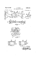
Fig. 1 is a sectional elevational view of the upper part or cutter head of a comminuting apparatus constructed in accordance with the present invention;
Fig. 2 is a top plan view of the knife or cutting tool;
Fig. 3 is a top view of the scraper;
Fig. 3a is an enlarged section taken along lines 3a'3a of Fig. 1 showing in exploded stage upper and lower scraper portions.
Fig. 4 is a top plan view, partly in section of a modified knife employable in this invention;
'Fig. 5 is an enlarged sectional view taken along lines 5-5 of Fig. 4;
Fig. 6 shows a cross-sectional view of a perforated plate and apertured support assembly employable in the invention;
Fig. 7 is a fragmentary top plan view of the perforated plate and apertured support therefor as seen in Fig. 6, the plate and support being partly broken away to indicate their relationship when placed in superposed position.
Fig. 8 is a fragmentary and enlarged detail view in section of the plate-support assembly seen in Fig. 6; and
Fig. 9 shows a fragmentary sectional view of the perforated plate and support assembly in modified form.
Referring now more particularly to the drawings, it Will be seen that the upper part of the comminuting apparatus is constructed for bodily removal from the 3 V 7 drive part of theapparatus (not'shown) which contains suitable drive means, usually an electric motor. The
cutter head proper comprises a housing 1 provided with engaging correspondingly shaped grooves 7b' and 'ltlain;
the hubs 7a' and 10 respectively. I 1 V Both the -scraper 4 and knife 7 are providedwith a plurality of arms, two such arms beingfshowninthe" drawing, and the knife '7 is provided on each of its arms 7 or blades with 'a coarse pre-cutting edge 5, serrated to provide a greater cutting surface, and with a smooth,
fine cutting edged. The blade surfaces are slanted, so thateach coarse edge 5 is disposed in a higher plane than the associated'fine edge 6. V r V I Scraper 4 proper is" of relatively reduced'height, is curved and-ascending toward'its hub At the outer surface of'hubflt) there are provided keyways 412 for removably receiving upper seraper portion or portions the toughness or other cutting characteristics of the material to be comminuated. 1
The blades of the scraper 4 ensure continuous removal of cornminuted material from the plate 11, this material being moved radially outwardly in the scraper chamber due to centrifugal force effects and leaving the chamber when brought by one'ofthe scraper blades to the outlet duct 1a from which it may be collected in any suitable receptacle. 7 7
4a 'for secure connection with the base, scraper 4 for a pur'pose'later referred to.
Supported on a shoulder 1c of the housing 1 is an annular plate or disc 11 provided with a plurality of small sharp-edged perforations 11a, and itrwill be seen that the perforated plate 1 1 is disposed a predetermined distance above the upper scraper portion 4a and directly below the knife 7, suiiicient clearance being left between the plate 11, and thetblades or arms 70 of thetknife to permit unimpeded rotation of the latter. The hub 10 of the scraper proper 4 is extended upwardly beyond the scraperparts 4, 4a and through the central aperture 11b of the perforated plate and is provided with a plurality of recesses 10b in eachiof which is seated a pair of curved plate springs15, which may .take the formv of Belleville washers, bearing against the bottom surface of the knife hub 7a. ,fIhe shaft 3 is provided with a further exter nally threaded extension 14 onto which are screwed an adjusting nut 12 and a lock nut 13, which are employed to determine the axial position oftthe knife7 relative to the plate ll as well asto ensure. retention of, the knife onthe shaft .35 The knife is, of course, subjected to i the resilient pressure exerted by the springs or Belleville Washers 15 whichbias itltoward and against the nut 12. The'lower surface of the hub 10 of the scraper 4 isprovided with an annular groove 16' into which extends an annular ledge 17 located concentricallyabout shaft 3 on a partition 18'arranged transversely acrossthe housing. 1 and defining the bottom ofthe chamber in which the scraper movesand into which'the food or other material in relativelyfinely ground and come minuted state falls from the perforated plate 11; The
.can'be seeir'from Fig. 1, since thekn'ife'shaft 3 is conventionallyreleasably" connected with the motor output shaft, the entire upper part ,of; the apparatus may be lifted from the drive part thereof whenever necessa y, to facilitate transportation, repair of the nrotor or any other operation dependent on, access, to the drive part of the apparatus. r
Referring now more particularly to Figs. 4'to 6 there isdisclosed' a curved knife ,20 having-a hubj.20a and a hub groove 20b. Knife blades 200 are curved in opposed relation, as shown and are provided with respective. serrated upper cutting edges21- for rotation normally in the direction of arrow 22'. The lower cuttingedges 21aaresubstantially inelined '(Fig. 5) and are disposed a predetermined, but regulatable distance from perforated cutting plate 11. Plate 11 is. provided with perforations 11a ofpredetermined diameter which are grouped, for instance, as indicated iu'Fig; 7. Plate 11 is coupled by means of groove and. key, as at 23, 24, to a heavy lower steel support plate 11b provided with apertures 11c grouped andspaced from each'other in a predetermined fashion, so that respectively grouped perforations 11a come to lie over and extend in accordance with the corresponding single apertures 11c of said support plate 11b. However, .the total cross-section of the perforations 11a is kept somewhat smaller than that-of the respective aperture 110.
It is, of course, possible to interchange perforated cutter plate 11 with another plate having difierently grouped perforations of various diameters relative to each other and to the apertures provided in the support plate 11b (see Figs. Sand 9). Fig. 8 indicates a perforated cutter plate 24 with a number of relatively large perforations 24a and a support plate 25 with aperture 25a, whereas in Fig. 9 there is depicted a perforated cutter plate 26- with a relatively large perforation 26a resting on support plate 25.
Reverting further to Fig. 6 it will be noted that spacings 11d locatedfbetween the respective groups of perforations. 11a approximately coincide with respective changeability of the perforated plates) inregards to the meat grinding or comminuting' apparatus A further novel feature hereinabove mentioned 'is that the .meatcomminuting apparatus may be used-in the fabrication of sausages by applying the ejector or scraper bladeconstructio'n as shown in Fig. '1 so thatthe ground meat will be-thoroughlymixed, whereas for production of: hamburgers or beefsteak tartar? the upper scraper portion-' lemay be-rcadily separated'fromthe hub 10' at 4b which is integrally connected to the base ejector 4. Thus ground or minced meat strings passing through the perforated cutter plate with predetermined fineness are unimpededly guided through the apertures of the respective support-plate resting on shoulder (Fig. 1), through a free space (upon removal of portion 4a) onto the curved upper surface 40 of scraper blade or blades 4, whence said minced meat strings are deviated toward the outlet 1a without being further subjected to crushing or like action as it would be the case, if the complementary scraper portion 4a were coupled with the scraper blades 4 as hereinabove explained.
Although Fig. 1 shows biasing or spring means accommodated in suitable recess 10b of hub 10, it is well understood that the arrangement of said spring means 15 may be had in a different manner and position, such as below the scraper or ejector means 4, 4a and between wall 18 and a collar (not shown) of shaft 3. The aforesaid spring means 15 may also be in the form of two or more superposed or juxtapositioned spring elements permitting accurate adjustment and positioning of knife cutting edge 6 relative to the selected perforated cutting plate 11 with predetermined number of sharpedged perforations.
Various changes and modifications may be made without departing from the spirit and scope of the present invention and it is intended that such obvious changes and modifications be embraced by the annexed claims.
Having thus described the invention, what is claimed as new and desired to be secured by Letters Patent, is:
l.A cutter head comprising a shaft rotatable about its axis and having opposite ends, a stationary annular plate provided with a plurality of small, sharp-edged perforations extending from one of the surfaces of said plate to the other, said plate being positioned coaxially with said shaft intermediate said ends thereof, a scraper provided with a central hub and carried at said hub thereof by said shaft for rotation with the latter adjacent said one surface of said plate and including a plurality of arms each having an edge fixedly spaced a small predetermined distance from said one surface of said plate, a multi-bladed cutting tool provided with a central hub and carried at said hub thereof by said shaft for rotation therewith adjacent said other surface of said plate and for axial displacement along said shaft, each of said blades being provided with a coarse cutting edge and a fine cutting edge, with the fine cutting edges being disposed closer to said other surface of said plate than the coarse cutting edges, said shaft being threaded at one of said ends thereof, an adjusting nut screwed onto said threaded end of said shaft and engageable with said hub of said cutting tool at that side thereof facing away from said plate and scraper, a lock nut screwed onto said threaded end of said shaft for securing said adjusting nut in position, and spring means interposed between said hub of said scraper and said hub of said cutting tool and bearing against said hub of the latter to bias the same toward and against said adjusting nut so as to maintain said hub of said cutting tool always in engagement with said adjusting nut, to thereby maintain the distance between said fine cutting edges of said blades and said other surface of said plate at the preset adjusted value.
A cutter head comprising a shaft rotatable about its axis and having opposite ends, a stationary annular plate provided with a plurality of small perforations extending from one of the surfaces of said plate to the other, said plate being positioned coaxially with said shaft intermediate said ends thereof, scraper means carried by said shaft for rotation with the latter adjacent and fixedly spaced from said one surface of said plate and including a plurality of scraper arms to remove comminuted material from said one surface of said plate, a multi-bladed cutting tool carried by said shaft for rotation therewith adjacent said other surface of said plate, each of said blades being provided with a coarse cutting edge and a fine cutting edge, with the latter being disposed closer to said other surface of said plate than said coarse cutting edge, a threaded extension arranged at one of said ends of said shaft, an adjusting nut screwed onto said threaded end of said shaft and engageable with said cutting :tool at that side thereof facing away from said plate and scraper means, a lock nut screwed onto said threaded end of said shaft for retaining said adjusting nut in position, cooperable means on said shaft and said cutting tool permitting axial displacement of the latter along said shaft, and resilient means acting on said cutting tool to bias the same toward and against said adjusting nut, whereby said cutting tool may be adjusted along said shaft by rotation of said adjusting nut while the latter ensures that the distance between said fine cutting edges of said blades and said other surface of said plate remains at the preset adjusted value.
3. In a cutter head according to claim 2; said cutting tool and said scraper means each being provided with a hub by means of which they are carried by said shaft, said resilient means comprising a plurality of pairs of curved plate springs supported by said hub of said scraper means and engaging said hub of said cutting tool.
4. In a cutter head according to claim 3; said hub of said scraper means being provided in its surface facing said cutting tool hub with a plurality of recesses defining seats for said plate spring pairs.
5. An apparatus for comminuting meat and like alimentary product comprising a shaft having a threaded end portion, rotatable knife means having a hub keyed to said shaft, said knife means being provided with an upper serrated cutting edge for precutting said product and with a lower cutting edge for finely cutting said precut product, superposed plate means positioned below said knife means, ejector blade means connected to said shaft and provided with a hub having a circular recess facing said knife means, spring means located in said recess and spacing said knife means from said plate means, and means in threaded engagement with said threaded portion of said shaft and adapted to adjust the position of said knife means relative to said superposed plate means via said spring means, said superposed plate means including a relatively thick support plate provided with apertures and a relatively thin cutting plate provided with perforations arranged to extend between said support plate and said lower cutting edge of said knife means, said ejector blade means communicating with an outlet for ejecting therethrough said comminuted product discharged from said cutting plate and passed through apertures of said support plate said perforations being in registry with said apertures.
6. An apparatus according to claim 5, said ejector blade means including a base blade portion and an upper blade portion connected to said base blade portion at the hub thereof and for removal from the same, to thereby enlarge the free passage from said apertures of said support plate onto said ejector blade means and to reduce crushing and scraping action on said comminuted product.
7. An apparatus for comminuting meat and like alimentary product comprising a housing having a wall with a shoulder, a shaft extending into said housing and having a threaded end portion, rotatable knife means having a hub keyed to said shaft, said knife means being provided with an upper coarse serrated cutting edge for precutting said product and with a lower fine cutting edge for finely cutting said precut product, superposed plate means positioned directly below said lower cutting edge of said knife means, ejector blade means connected to said shaft and provided with a hub, spring means surrounding said shaft for spacing said knife means from said plate means, means in threaded engagement with said threaded portion of said shaft and adapted to adjust 'via said spring means the position of said knife means,
said superposed plate means including a relatively thick support-plate provided with apertures and a relatively thin cutting plate'provided with perforations arranged to x beme n i ai s p e P a e and Said lower; utt n V r the interior'of said=housing and for ejecting therethrough said comminuted product, when discharged from said cutting plate and passed through apertures of said support plate onto said ejector blade means.
8. An apparatus according to clalm 7, said ejector blade means forming a base blade" portion connected to,
said hub thereof and. spacedifrom said support plate to thereby" ensure free passage from, said apertures of'said support plate onto said base blad erportion L a References Cited in thefile of this'patent I j v UNITED STATES PATENTS 770,038 Bach Sept. 13, 1904 1,629,377 Buckwalter May 17,. 1927 2,771,636 McIntosh a al. Nov 27, 1956 2,840,318 7 Schnell -a June 24, 1958 i V FOREIGN PATEN S 1 315,809 Switzerland Oct. 31, 1956
Applications Claiming Priority (1)
| Application Number | Priority Date | Filing Date | Title |
|---|---|---|---|
| DE2953179X | 1957-02-20 |
Publications (1)
| Publication Number | Publication Date |
|---|---|
| US2953179A true US2953179A (en) | 1960-09-20 |
Family
ID=8017456
Family Applications (1)
| Application Number | Title | Priority Date | Filing Date |
|---|---|---|---|
| US689354A Expired - Lifetime US2953179A (en) | 1957-02-20 | 1957-10-10 | Meat comminuting apparatus |
Country Status (1)
| Country | Link |
|---|---|
| US (1) | US2953179A (en) |
Cited By (7)
| Publication number | Priority date | Publication date | Assignee | Title |
|---|---|---|---|---|
| US3221788A (en) * | 1963-08-02 | 1965-12-07 | Alvin W Hughes | Emulsifier |
| US3292212A (en) * | 1964-05-27 | 1966-12-20 | Midland Ross Corp | Pelleting apparatus |
| US3738596A (en) * | 1971-12-23 | 1973-06-12 | Foamat Foods Corp | Apparatus for breaking up a dehydrated food mass |
| US3865320A (en) * | 1973-01-08 | 1975-02-11 | Joseph E Bowles | Soil pulverizing device |
| US4019689A (en) * | 1974-10-18 | 1977-04-26 | Beed (Dishwashers) Limited | Food material chopper |
| US20070181719A1 (en) * | 2003-03-07 | 2007-08-09 | Emerson Electric Co, | Food waste reduction mechanism for disposer |
| US20140299694A1 (en) * | 2013-04-08 | 2014-10-09 | Conair Corporation | Locking mechanism for food processor blade assembly |
Citations (5)
| Publication number | Priority date | Publication date | Assignee | Title |
|---|---|---|---|---|
| US770038A (en) * | 1904-04-27 | 1904-09-13 | Emil Bach | Machine for stripping and crushing grape-berries. |
| US1629377A (en) * | 1924-07-01 | 1927-05-17 | Enterprise Mfg Co | Feed regulator for grinding mills |
| CH315809A (en) * | 1954-09-18 | 1956-09-15 | Carl Schnell Maschinenbau Fa | Shredder |
| US2771636A (en) * | 1953-07-22 | 1956-11-27 | Monsanto Chemicals | Apparatus for extruding thermoplastic material |
| US2840318A (en) * | 1956-03-19 | 1958-06-24 | Griffith Laboratories | Comminuting machine having perforated plate and rotary cutter |
-
1957
- 1957-10-10 US US689354A patent/US2953179A/en not_active Expired - Lifetime
Patent Citations (5)
| Publication number | Priority date | Publication date | Assignee | Title |
|---|---|---|---|---|
| US770038A (en) * | 1904-04-27 | 1904-09-13 | Emil Bach | Machine for stripping and crushing grape-berries. |
| US1629377A (en) * | 1924-07-01 | 1927-05-17 | Enterprise Mfg Co | Feed regulator for grinding mills |
| US2771636A (en) * | 1953-07-22 | 1956-11-27 | Monsanto Chemicals | Apparatus for extruding thermoplastic material |
| CH315809A (en) * | 1954-09-18 | 1956-09-15 | Carl Schnell Maschinenbau Fa | Shredder |
| US2840318A (en) * | 1956-03-19 | 1958-06-24 | Griffith Laboratories | Comminuting machine having perforated plate and rotary cutter |
Cited By (9)
| Publication number | Priority date | Publication date | Assignee | Title |
|---|---|---|---|---|
| US3221788A (en) * | 1963-08-02 | 1965-12-07 | Alvin W Hughes | Emulsifier |
| US3292212A (en) * | 1964-05-27 | 1966-12-20 | Midland Ross Corp | Pelleting apparatus |
| US3738596A (en) * | 1971-12-23 | 1973-06-12 | Foamat Foods Corp | Apparatus for breaking up a dehydrated food mass |
| US3865320A (en) * | 1973-01-08 | 1975-02-11 | Joseph E Bowles | Soil pulverizing device |
| US4019689A (en) * | 1974-10-18 | 1977-04-26 | Beed (Dishwashers) Limited | Food material chopper |
| US20070181719A1 (en) * | 2003-03-07 | 2007-08-09 | Emerson Electric Co, | Food waste reduction mechanism for disposer |
| US7500628B2 (en) * | 2003-03-07 | 2009-03-10 | Emerson Electric Co. | Food waste reduction mechanism for disposer |
| US20140299694A1 (en) * | 2013-04-08 | 2014-10-09 | Conair Corporation | Locking mechanism for food processor blade assembly |
| US9867504B2 (en) * | 2013-04-08 | 2018-01-16 | Conair Corporation | Locking mechanism for food processor blade assembly |
Similar Documents
| Publication | Publication Date | Title |
|---|---|---|
| US4004742A (en) | Rotary meat grinder with bone-collecting facilities | |
| US2712904A (en) | Unitary wood chipping disk with removable knife assembly and independent wear plate | |
| US4153208A (en) | Mincing machine for grinding up food | |
| US2953179A (en) | Meat comminuting apparatus | |
| US2840318A (en) | Comminuting machine having perforated plate and rotary cutter | |
| US2360357A (en) | Grinding mill | |
| US2974701A (en) | Continuous chopper | |
| US2325779A (en) | Juice extractor | |
| US4600160A (en) | Chopper blade assembly | |
| US2854047A (en) | Shredder spool with bar knives | |
| US3061207A (en) | Rotary wood chippers | |
| US3429350A (en) | Comminuting device | |
| US2801665A (en) | Apparatus for comminuting meat and vegetables | |
| US973761A (en) | Spice-mill. | |
| US3123116A (en) | hughes | |
| US2218119A (en) | Food crusher | |
| US3219081A (en) | Comminuting machine for meat or other food products | |
| US3314459A (en) | Wood chipping apparatus | |
| US633646A (en) | Bark cutting and reducing machine. | |
| US2210006A (en) | Food grinding machine | |
| US453486A (en) | Bark-mill | |
| US1641699A (en) | Ice-shaving machine | |
| US1869220A (en) | Meat cutter | |
| GB359939A (en) | Apparatus for grinding, milling, slicing and the like | |
| US2905217A (en) | Food chopper knife mounting |