US2995209A - Operating mechanism for rail lubricator - Google Patents
Operating mechanism for rail lubricator Download PDFInfo
- Publication number
- US2995209A US2995209A US729735A US72973558A US2995209A US 2995209 A US2995209 A US 2995209A US 729735 A US729735 A US 729735A US 72973558 A US72973558 A US 72973558A US 2995209 A US2995209 A US 2995209A
- Authority
- US
- United States
- Prior art keywords
- shaft
- plunger
- reservoir
- clutch
- lubricant
- Prior art date
- Legal status (The legal status is an assumption and is not a legal conclusion. Google has not performed a legal analysis and makes no representation as to the accuracy of the status listed.)
- Expired - Lifetime
Links
Images


Classifications
-
- B—PERFORMING OPERATIONS; TRANSPORTING
- B61—RAILWAYS
- B61K—AUXILIARY EQUIPMENT SPECIALLY ADAPTED FOR RAILWAYS, NOT OTHERWISE PROVIDED FOR
- B61K3/00—Wetting or lubricating rails or wheel flanges
Landscapes
- Engineering & Computer Science (AREA)
- Mechanical Engineering (AREA)
- Transmission Devices (AREA)
Description
g- 1961 o. F. MAGNUS 2,995,209
OPERATING MECHANISM FOR RAIL LUBRICATOR Filed April 21, 1958 5 Sheets$heet l INVENTOR. 06cm? F MHGNUS BY WM f HTTOPNEY 5 Sheets-Sheet 3 Aug. 8, 1961 o. F. MAGNUS OPERATING MECHANISM FOR RAIL LUBRICATOR Filed April 21, 1958 5 5 M w 6 25 2 .m mm m MJQJMZ 1 M6 v 6 MA a U M W m I 6 \EMME \V\ mm M M5 55 m 2 azz 0 a 8 z 0 4 z 4 HI m 2 T 6 a 1 2 q I T Aug. 8, 1961 o. F. MAGNUS OPERATING MECHANISM FOR RAIL LUBRICATOR 5 Sheets-Sheet 4 Filed April 21, 1958 INVENTOR. 05cm? F MnGNus BY WM 5. Wm
p, ULAP Aug, 8, 1961 o. F. MAGNUS OPERATING MECHANISM FOR RAIL LUBRICATOR Filed April 21, 1958 5 Sheets-Sheet 5 INVENTOR F MQGNUS FITTO EN EY United States Patent 2,995,209 OPERATING MECHANISM FOR RAIL LUBRICATOR Oscar F. Magnus, Tinley Park, 111., assignor to American Brake Shoe Company, New York, N.Y., a corporation of Delaware Filed Apr. 21, 1958, Ser. No. 729,735 3 Claims. (Cl. 184-3) The invention relates to lubricating devices for railway rails and more particularly of the type shown in Heidenthal Patent 2,185,810, dated January 2, 1940, although not limited to such use.
Rail lubricators of the Heidenthal type have been in commercial use for many years and have given generally satisfactory service. These devices comprise a wheeloperated ramp on the running rail driving a series of lubricant gear pumps located in the bottom of a lubricant reservoir alongside the track. The drive comprises an oscillatory rotary flexible shaft involving two universal joints and a takeup joint between the track and an upper shaft in the reservoir. Additional oscillatory linkage connects the upper shaft and an overrunning clutch device on the pump shaft in the bottom of the reservoir.
The drive of the Heidenthal type lubricator thus involves a long chain of oscillatory members with a large number of working joints all subject to lost motion and wear. Due to the nature of a wheel-operated drive, it is subject to rapid impulses of short amplitude which are in the nature of hammer blows. Lost motion in the working joints of oscillatory parts is particularly serious because it is cumulative and reduces the effective unidirectional impulses applied to the pumps. It is also serious because of the progressive wear caused by the battering of the numerous working joints which aggravates the lost motion and wears out the machine. Furthermore, in the Heidenthal type lubricator, the location of the drive and check clutches in the bottom of the reservoir makes them difficult to service.
An object of the present invention is to alleviate some or all of the difiiculties of the prior lubricator and. to simplify it.
According .to a preferred form of the present invention, theoperating mechanism comprises a simple compact rocker having a short wheel-operated plunger which oscillates a rock shaft mounted in a housing directly on the running rail. The rock shaft is tightly connected to a special type of flexible cable shaft which in turn is directly connected to a special upper shaft assembly in the top of the lubricant reservoir. The drive clutch and check brake are located on this upper shaft so that the ,drive mechanism between the upper shaft and the pump is subject to uni-directional movement only. By the practice of the invention reciprocating movement of the plunger is transmitted directly to the drive clutch in the lubricant reservoir, substantially free of working joints, thus greatly reducing lost motion and its attendant evils.
Other objects and features of the inventionswill be more apparent from the following description and claims .when considered with the accompanying drawings in which; i I I f, FIG. 1 is-a plan view showing the general arrangement of lubricant applying apparatus, wheel-operated plunger mechanism, and lubricant reservoir;
,FIG. 2 is a detail of the flexible cable shaft, showing its multi-convolution construction; FIG. 3 is a detail of the floating bearing seal in the reservoir wall through which the operating shaft passes, taken on the line 33 of FIG. 1;
FIG. 4 is a plan view, withparts broken'away, of the plunger mechanism;
.urge the plunger upwardly.
Patented Aug. 8, 1961 ice FIG. 5 is a plan of the flexible cable shaft with its end connections;
FIG. 6 is a vertical section taken, on the line 6-6 of FIG. 4, through the plunger mechanism;
FIG. 7 is a transverse section taken through the running rail and plunger mechanism, on the line 7-7 of FIG. 1;
FIG. 8 is a transverse section through the running rail, taken on the line 88 of FIG. 1, and showing the plunger mechanism in elevation;
FIG. 9 is a detail, taken on the line 9--9 of FIG. 1, showing how the D-bar and delivery plate are bolted together;
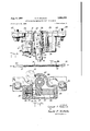
FIG. 10 is a plan view of the reservoir with cover removed, showing the drive and pump mechanism;
FIG. 11 is a side elevation of the reservoir, with parts broken away to show the drive and pump mechanism;
FIG. 12 is a side elevation of the rocker forming part of the plunger mechanism;
FIG. 13 is a longitudinal section through the upper reservoir shaft showing how the drive clutch and check brake are mounted and how the flexible cable shaft is connected;
FIG. 14 is a transverse section through the drive clutch, taken on the line 1414 of FIG. 13, and I FIG. 15 is a section on the line 1515 of FIG. 8 showing the gasket and the distributor strip of the ap plying mechanism.
In the following description and in the claims, various details will be identified by specific names for convenience, but they are intended to be as generic in their application as the art will permit.
Like reference characters denote like parts in the several figures of the drawings.
In the accompanying drawings and in the description forming part of this specification, certain specific disclosure of the invention is made for purposes of explanation, but it will be understood that the details may be modified in various respects without departure from the broad aspect of the invention.
Referring now to the drawings and more particularly to FIG. 1, the invention will be first generally described. It comprises a plunger mechanism 10 mounted on the running rail 11, having a plunger 12 actuated by the treads of wheels running on the rail. The depressing of the plunger oscillates, rotarily, a flexible cable shaft 13 which (FIG. 10) oscillates an upper overrunning clutch assembly 14 journaled in the reservoir 15. Clutch assembly 14 drives uni-directionally gear pump 16 located in the bottom of the reservoir. The pump in turn forces lubricant from the reservoir through discharge piping 17 to applying slots 18 which deliver lubricant to the-flanges 65 of railway wheels 19 (FIG. 8).
Referring now more particularly to FIGS. 4 to 8, the operating mechanism will now be described more in detail. The operating mechanism comprises a housing body 21 and a back plate 22 connected by machine screws 23. The body has an upper compartment and a lower compartment. The back plate 22 and front wall of the housing 21 have bushings 24, 25 for journaling a rocker member 26.
The rocker 26, which may be an integral casting, FIG. 12, comprises a hollow shaft 27 having hubs 28, 29 journaled in the bushings 24, 25, an upper plunger 12 near the back of the shaft and a lower arm 31 depending from the middle of the shaft. The housing has a recessed seat 34, and the lower arm has a boss 35, for centering a helical return spring 36 which operates to The housing 21 has a top 0 g 32 through the plunger 12 projects. The housing has a rear open- 3 ing 37, FIG. 7; it has a front opening 38 closed by a plate 39 removably held in position by a bolt 40.
The front opening 38 constitutes a recess for an adjustable .abutment 43 to limit upward movement of the plunger 12. This adjustment comprises a stop bolt whose head constitutes abutment 43 against which the lower arm 31 engages, and a shank 44. The front recess 38 comprises a head portion for the bolt head 43, a shank portion for the bolt shank 44, and a shim portion for the extra shims 45. The cover 39 has a holding fin 46 engageable in the shank portion to hold the stop bolt 43 in position.
It will be understood that the amplitude of movement of the plunger 12 controls the amount of lubricant fed to the applying devices. By changing the number or thickness of shims 47 under the bolt head 43, the amplitude of movement of the lower arm 31 can be controlled.
The thickness of shims 47 under the bolt head determines the uppermost position of the plunger; it also controls the amplitude of rocker movement, when the plunger is depressed by any given car wheel. It will be understood that the average wheel has a false flange which engages the plunger. The size of the false flange determines the amplitude of rocker movement, with any given shim adjustment.
To change shim adjustment, it is only necessary to remove the front plate 39, remove the stop bolt 43, and place one or more of the spare shims 45 under the bolt head, or remove one or more of the shims 47 under the bolt head and place them around the shank 44 in the spare recess.
The plunger mechanism .10 is secured to the running rail 11 in the following manner (see FIGS. 1, 7, 8). Through bolts 48 pass through lugs on the housing 21, cover plate 22, spacer plate 49, a reinforcing D-bar 50, the rail web; and D-bar 51 and delivery plate 52 of the applying mechanism.
Referring now to FIGS. 1, 7, 8, 9 and 15, the lubricant applying apparatus will now be described. This comprises a D-bar 51 fitting the rail 11 and a delivery plate 52 clamped thereto by short bolts 55 (-FIG. 9), by through bolts 48, and by end bolts 56. The plates are spaced apart by U-shaped gaskets 57 and by spacer strips 62 to form two delivery spaces 60. The D-bar 51 has a back groove 53 to receive the heads of short bolts 55 to keep them from turning.
The delivery slot 18 is formed by machining away the lower edge of the rail head and by beveled surface 61 on the delivery plate 52. The outer surface of the delivery plate 52 is also beveled at 64 to facilitate clearing the wheel flange.
The delivery plate 52 has two inlets to which are connected fittings 58 leading from distributing pipes 17. These fittings supply lubricant to the spaces 60, defined by the U-shaped gaskets 57 (FIG. 15), between the bars 51, 52. Special equalizer strips 59 are set in the D-bar 51 to help distribute the lubricant from spaces 60 uniformly along the length of the adjacent portion of de livery slot 18. There is a spacing strip 62 at each of the bolts, each strip having an opening through which its bolt passes. This arrangement limits the lubricant spaces 60 to areas fed by fittings 58 and defined by the U-shaped gaskets 57.
It will be understood that, as lubricant is delivered to the fittings 58, it enters the lubricant spaces 60 between the bars and is distributed by strips 59 along the delivery slot 18 where it builds up and from which it is wiped off by the wheel flanges 65.
All of the barsD-bars t), 51 and delivery bar 52 may extend the entire length of the lubricator from one end bolt 56 to the other to reinforce the running rail. The underside of the head of rail 11, and beveled surface 61 on plate 52, may extend the entire length of the lubricator-even though the delivery slot 18 is supplied with lubricant only at the lubricant spaces 60. Outside bevel 64 extends the entire length of the lubricator.
Certain parts of the drive mechanism in the reservoir 15 are oscillated while others are driven unidirectionally. All moving parts of the flexible cable shaft and of the plunger mechanism are oscillated.
The oscillating parts transmit torque in one direction only; that is to say, in the driving direction. They do not transmit torque in the retrograde or idle direction. To assist in understanding the invention, solid arrows are used to indicate the direction in which torque is transmitted; dotted arrows indicate the retrograde or idle direction. The direction of parts having uni-directional movement are indicated by solid arrows only.
Referring now to FIGS. 10, 11, 13 and 14, the mechanism in the rmervoir 15 will now be described. It will be understood that the tank 15 is located in the ground alongside of the track, as indicated in the above-mentioned Heident-hal patent. The tank has a removable cover and may be filled with lubricant up to the upper shaft.
On the bottom of the reservoir is a single unit gear pump 16 which may be of the type shown in the abovementioned Heidenthal patent. The gear pump has a screened inlet 66 through which lubricant enters. The gears (not shown) discharge the lubricant through a discharge pipe 67, which passes through a suitable fitting 68 in the reservoir wall and thence to piping 17 for delivery to the track. The pump 16 is driven by a sprocket 69 mounted on the shaft of one of its gears. The sprocket 69 is driven by a chain 70, which in turn is driven by an upper sprocket 71 mounted on the upper counter shaft assembly 14.
The upper or clutch shaft assembly 14 comprises a clutch coupling sleeve 74 having a reduced hub 75 which is journaled in a floating bearing, see FIG. 3. The floating bearing comprises inner and outer grommet caps 76, holding sponge rubber grommets 78 against the margin of an opening in the wall of the reservoir tank. These caps 76 are secured to the tank wall by bolts 77.
The clutch coupling sleeve 74 houses an overrunning drive clutch 79 which comprises an outer race 80 surrounding an inner cam member 81 with rollers 82 therebetween. Cover rings 83 hold the rollers 82 axially in position; the cover rings ride on bushings 84 hearing on the inner clutch shaft 85. The cam race 81 is suitably keyed to the inner clutch shaft 85 and the outer race 80 is suitably keyed to the clutch coupling sleeve 74.
The inner shaft 85 passes through an overrunning check brake 88 which is similar in construction to the drive clutch 79 except that it overruns in the opposite direction. keyed to the inner shaft 85 and the outer race 90 of the check brake is keyed to the supporting block 91 bolted to the reservoir wall.
The drive clutch 79 and check brake 88 form a unitary assembly, suitable spacing washers being provided, the inner shaft 85 being provided with a head 92 at one end and a pinned collar 93 at the other. The upper sprocket 71 is pinned to the inner shaft 85.
Thus the upper shaft assembly is journaled at one end in the floating bearing 76, 78 and at the other end in the support block 91. The floating bearing 76, 78 also seals the shaft opening. The inner shaft 85 is journaled in the bearing block 91 and the coupling 74 is rotatably mounted on inner shaft 85.
It will be understood that, as the clutch coupling 74 is oscillated by passage of trains over the track, the drive clutch 79 drives the sprocket 71 uni-directionally, while the check brake 88 prevents retrograde movement of the sprocket.
The flexible cable shaft 13 and its connections with input and output shafts will now be described. As shown in FIG. 2, the cable shaft 13 comprises a generally straight flexible core wire 94 with a plurality of layers of wire helical convolutions surrounding the core wire. The alternate layers are wound in opposite directions.
The inner cam race 89 of the check brake is It is important that torque be transmitted in such direction as to tighten the outermost convolution 95; or conversely, the direction of winding of the outermost convolution 95 should be such that transmission of torque in the desired direction tightens the convolution. V
When the end A of the shaft 13 is the driving or input end and the end B is the driven or output end, transmission of torque in the direction of the arrow in FIG. 2 will tighten the outermost convolutions 95. Thus, when the shaft must be rotated in a counter-clockwise direction, looking in the direction of power flow (rail to reservoir) the outer convolution 95 must be given a right lay.
It has been found that with a relatively short length of flexible shaft of reasonably straight configuration, a shaft having an outside diameter of three-quarters of an inch will transmit the necessary torque with little or no torsional deflection. Any slight torsional deflection is useful to cushion the blows applied to the plunger by the fast moving wheels.
It will be understood that, when the plunger 12 is depressed to compress the spring 36, the flexible shaft 13 is turned without transmitting torque. The release of the spring 36 applies torque to the flexible shaft 13 which causes the drive clutch 79 to drive the pump.
The end fittings 96, 97 of the cable shaft 13 are connected to the cable in any desired manner. It will be understood that the cable shaft per se and its connection to its end fittings form no part of the present invention except in the combination shown.
The connection between flexible cable shaft 13 and plunger mechanism will now be described. See FIGS. 7 and 12. The hub 29 of the rock shaft 27 has a horizontal slit 98 and a vertical drill hole. The inside of the shaft 27 has a square cross section as has the outside of the reduced shank 99 on cable fitting 96. A suitable bolt 100 passes through the drill holes in hub and shank. A nut on the bolt 100 tightly clamps shank 99 and hub 29 together, forming a connection having no lost motion.
Referring now to FIGS. 3 and 13, for connecting the flexible shaft 13 to the clutch coupling 74, the inside of the coupling 74 has a square cross section as has the out side of the reduced shank 101 on cable fitting 97. The coupling 74 in addition has an elongate slot 102 passing entirely through. A bolt 103 passes through the slot 102 and through a drill hole in the square shank 101 for tightly securing the shank and coupling together.
The elongate slot 102 provides for adjustment permitting some variation in the location of the reservoir with respect to the track. Furthermore, the slot 102 permits some axial sliding movement between shank 101 and coupling 74 in the event trains running over the track cause the track to move laterally with respect to the lubricant reservoir. At the same time the bolts 100 and 103 passing through the fittings on the flexible cable 13 prevent the cable being accidentally completely disconnected from the rock shaft 27 or from the clutch coupling 74.
If desired, a plastic sleeve (not shown) may surround the flexible cable 13 and its end connections to protect these parts from the weather. This plastic sleeve is not necessary to transmit power from operating mechanism to pump.
The operation of the lubricator should be apparent from the above description. Briefly, when a car wheel runs along the running rail, it depresses the plunger 12; this compresses the spring 36 and imparts a retrograde movement to the flexible shaft 13 and to the drive clutch 79, the check clutch 8S preventing retrograde movement of the pump 16. After the wheel has passed, the spring 36 returns the plunger, applies torque to the flexible shaft 13, causing the drive clutch 79 to drive the pump 16, the check clutch 88 overrunning.
If desired, however, the action of the drive clutch and check brake may be reversed so that the pump is driven on the down stroke of the plunger, but it is preferred to have the drive stroke occur under the action of the return spring.
Thus a rail lubricator has been provided, which reduces lost motion and wear and yet is relatively inexpensive, and reliable in operation. Even though the reservoir is located remote from the nail, the reciprocating rotary drive between rail and drive clutch is practically free of working joints. The compact nature of the rock member and the absence of universal joints and slip joints in the flexible shaft, help minimize lost motion. It will be understood that lost motion between the overrunning drive clutch and pump is not serious since these parts operate uni-directionally. Further, the location of the overrunning drive clutch and check brake at the top of the reservoir make them easier to service; and the shim arrangement facilitates adjusting the amplitude of rock member movement, which in turn controls the amount of lubricant fed to the rail.
While certain novel features of the invention have been disclosed herein, and are pointed out in the annexed claims, it Will be understood that various omissions, substitutions and changes may be made by those skilled in the art without depart-ing from the spirit of the invention.
What is claimed is:
1. In a rail lubricator, a track including a running rail, delivery devices mounted on the track for applying lubricant to wheels of rolling stock, operating mechanism mounted on said track, a lubricant reservoir, a pump receiving lubricant from said reservoir and delivering it to said delivery devices, driving mechanism between said operating mechanism and said pump, said driving mechanism comprising a stationary bearing and a stationary support sleeve in line therewith, an overrunning clutch assembly comprising an oscillatable drive sleeve having one end journalled in said bearing and having its other end extending adjacent said support sleeve, an inner shaft, means journalling said inner shaft within said support sleeve, said inner shaft having a cantilever end projecting from said support sleeve into said drive sleeve, means journalling said drive sleeve on said cantilever end, an overrunning check brake having an outer race within said support sleeve and an inner race secured to said inner shaft, an overrunning drive clutch having an outer race within said drive sleeve and an inner race secured to said inner shaft, and means driving said pump from the end of said inner shaft opposite said cantilever end.
2. in the rail lubricator of claim 1, said pump and said stationary support being mounted in said reservoir, the wall of said reservoir having an opening, said stationary bearing comprising a yieldable seal around said opening constituting a floating bearing for said drive sleeve.
3. In a rail lubricator, a track including a running rail, delivery devices mounted on said track for applying lubricant to the wheels of rolling stock, a lubricant reservoir located alongside the track, a pump in said reservoir and receiving lubricant therefrom, an overrunning clutch in said reservoir, said clutch having a rotary input member whose axis is disposed transversely of the running rail, drive means connecting the output of said clutch and said pump, a conduit connecting the discharge of said pump and said delivery devices, a support attached to said running rail, an upwardly projecting plunger, said support and plunger being disposed on the outer side of said running rail facing said reservoir, pivot means pivoting said plunger on said support, the axis of said pivot means being disposed transversely of the running rail, means yieldably urging said plunger upwardly into the path of the treads of said wheels, a flexible cable shaft, means connecting one end of said flexible cable shaft to said plunger at said pivot means, and means connecting the other end of said flexible cable shaft to said clutch input member whereby to minimize the number of oscillatory working joints between said plunger and said overrunning clutch.
References Cited in the file of this patent UNITED STATES PATENTS Epple Jan. 9, 1917 Lebesnerois Oct. 29, 1929
Priority Applications (1)
| Application Number | Priority Date | Filing Date | Title |
|---|---|---|---|
| US729735A US2995209A (en) | 1958-04-21 | 1958-04-21 | Operating mechanism for rail lubricator |
Applications Claiming Priority (1)
| Application Number | Priority Date | Filing Date | Title |
|---|---|---|---|
| US729735A US2995209A (en) | 1958-04-21 | 1958-04-21 | Operating mechanism for rail lubricator |
Publications (1)
| Publication Number | Publication Date |
|---|---|
| US2995209A true US2995209A (en) | 1961-08-08 |
Family
ID=24932382
Family Applications (1)
| Application Number | Title | Priority Date | Filing Date |
|---|---|---|---|
| US729735A Expired - Lifetime US2995209A (en) | 1958-04-21 | 1958-04-21 | Operating mechanism for rail lubricator |
Country Status (1)
| Country | Link |
|---|---|
| US (1) | US2995209A (en) |
Cited By (3)
| Publication number | Priority date | Publication date | Assignee | Title |
|---|---|---|---|---|
| US4556127A (en) * | 1983-10-17 | 1985-12-03 | Trak-Tech, Inc. | Railway track lubricator |
| US5722509A (en) * | 1996-05-14 | 1998-03-03 | Consolidated Rail Corporation | Flange oiler |
| US6719095B2 (en) * | 2000-09-22 | 2004-04-13 | Lincoln Industrial Corporation | Railroad track lubrication and monitoring thereof |
Citations (9)
| Publication number | Priority date | Publication date | Assignee | Title |
|---|---|---|---|---|
| US1211424A (en) * | 1915-03-10 | 1917-01-09 | Carl Henry Epple | Flange and rail lubricator. |
| US1733416A (en) * | 1925-08-13 | 1929-10-29 | Goodrich Co B F | Sealing device for shafts |
| US2036528A (en) * | 1934-09-26 | 1936-04-07 | Elmer G Kesling | Flexible shaft |
| US2055939A (en) * | 1934-08-11 | 1936-09-29 | Charles A Miller | Rail and flange lubricator |
| US2185810A (en) * | 1936-05-29 | 1940-01-02 | American Brake Shoe & Foundry | Rail lubricator |
| US2498519A (en) * | 1948-01-30 | 1950-02-21 | Poor & Co | Actuating means for rail lubricating pumps |
| US2573361A (en) * | 1947-02-13 | 1951-10-30 | Libbey Owens Ford Glass Co | Torsion transmitting glass shaft and method of manufacture |
| US2643738A (en) * | 1949-03-12 | 1953-06-30 | American Brake Shoe Co | Pump actuating system for rail and flange lubricators |
| US2718299A (en) * | 1950-06-01 | 1955-09-20 | Verne L Atwater | Medicinal dispenser |
-
1958
- 1958-04-21 US US729735A patent/US2995209A/en not_active Expired - Lifetime
Patent Citations (9)
| Publication number | Priority date | Publication date | Assignee | Title |
|---|---|---|---|---|
| US1211424A (en) * | 1915-03-10 | 1917-01-09 | Carl Henry Epple | Flange and rail lubricator. |
| US1733416A (en) * | 1925-08-13 | 1929-10-29 | Goodrich Co B F | Sealing device for shafts |
| US2055939A (en) * | 1934-08-11 | 1936-09-29 | Charles A Miller | Rail and flange lubricator |
| US2036528A (en) * | 1934-09-26 | 1936-04-07 | Elmer G Kesling | Flexible shaft |
| US2185810A (en) * | 1936-05-29 | 1940-01-02 | American Brake Shoe & Foundry | Rail lubricator |
| US2573361A (en) * | 1947-02-13 | 1951-10-30 | Libbey Owens Ford Glass Co | Torsion transmitting glass shaft and method of manufacture |
| US2498519A (en) * | 1948-01-30 | 1950-02-21 | Poor & Co | Actuating means for rail lubricating pumps |
| US2643738A (en) * | 1949-03-12 | 1953-06-30 | American Brake Shoe Co | Pump actuating system for rail and flange lubricators |
| US2718299A (en) * | 1950-06-01 | 1955-09-20 | Verne L Atwater | Medicinal dispenser |
Cited By (3)
| Publication number | Priority date | Publication date | Assignee | Title |
|---|---|---|---|---|
| US4556127A (en) * | 1983-10-17 | 1985-12-03 | Trak-Tech, Inc. | Railway track lubricator |
| US5722509A (en) * | 1996-05-14 | 1998-03-03 | Consolidated Rail Corporation | Flange oiler |
| US6719095B2 (en) * | 2000-09-22 | 2004-04-13 | Lincoln Industrial Corporation | Railroad track lubrication and monitoring thereof |
Similar Documents
| Publication | Publication Date | Title |
|---|---|---|
| US4334596A (en) | Hydraulic fluid-operated railway track lubricating apparatus | |
| US3147822A (en) | Rail and flange lubricating apparatus | |
| US2995209A (en) | Operating mechanism for rail lubricator | |
| CN1220640A (en) | Power take off device from endless conveyor | |
| US1760902A (en) | Lubricant-distributing apparatus | |
| US2185810A (en) | Rail lubricator | |
| US2643738A (en) | Pump actuating system for rail and flange lubricators | |
| US4556127A (en) | Railway track lubricator | |
| US1765477A (en) | Vibration-dampening device | |
| US1880672A (en) | Wheel flange oiler | |
| US2349259A (en) | Railroad track equipment | |
| US2547609A (en) | Drilling apparatus | |
| US2486600A (en) | Rail lubricator | |
| US2401303A (en) | Railway lubricator | |
| US1626782A (en) | Swing-pipe mechanism | |
| CN209227338U (en) | Clutch and building machinery for building machinery | |
| US2398935A (en) | Railroad track equipment | |
| US2498519A (en) | Actuating means for rail lubricating pumps | |
| US1948747A (en) | Elevator-guide-rail lubricator | |
| US4489809A (en) | Railroad track deflection activated grease pump | |
| US1500588A (en) | Power transmission | |
| US2885029A (en) | Multipoint greasing system | |
| US1944272A (en) | Flange oiler | |
| US2050776A (en) | Section car | |
| US1257776A (en) | Driving mechanism for automobiles and the like. |