US3024924A - Railroad car hopper gate and coupler cam actuating means - Google Patents
Railroad car hopper gate and coupler cam actuating means Download PDFInfo
- Publication number
- US3024924A US3024924A US707578A US70757858A US3024924A US 3024924 A US3024924 A US 3024924A US 707578 A US707578 A US 707578A US 70757858 A US70757858 A US 70757858A US 3024924 A US3024924 A US 3024924A
- Authority
- US
- United States
- Prior art keywords
- cam
- car
- track
- laterally
- coupler
- Prior art date
- Legal status (The legal status is an assumption and is not a legal conclusion. Google has not performed a legal analysis and makes no representation as to the accuracy of the status listed.)
- Expired - Lifetime
Links
Images


Classifications
-
- B—PERFORMING OPERATIONS; TRANSPORTING
- B61—RAILWAYS
- B61D—BODY DETAILS OR KINDS OF RAILWAY VEHICLES
- B61D7/00—Hopper cars
- B61D7/14—Adaptations of hopper elements to railways
- B61D7/16—Closure elements for discharge openings
- B61D7/24—Opening or closing means
- B61D7/30—Opening or closing means controlled by means external to cars
Definitions
- This invention relates generally to novel model railroad constructions, and is particularly concerned with a model railroad-car mechanism adapted to be operated by a fixed cam.
- model railroad equipment As is well known to those versed in the art, the design and manufacture of model railroad equipment is con stantly confronted with the problems of limited space in which to simulate full-size railroad equipment. This problem is compounded in the production of HO-size model railroad apparatus, as such apparatus is of very highly reduced scale and accurately simulates the details of full-size equipment.
- the space problem is particularly acute in the region between the track rails and underside of the railroad cars, as this region must accommodate the operating mechanisms of the wheel trucks and couplers.
- One object of the present invention resides in the pro vision of means for actuating a mechanism of a model railroad car from the underside thereof, which means is adapted to be located in the space between the track rails and the underside of the car body, all without obstructing or in any way adversely affecting normal operation of conventional model railroad cars passing over the actuating means.
- Another specific object of the present invention resides in the provision of a novel hoppencar construction for model railroads, which construction is adapted to be actuated for opening and closing the hopper gates by merely positioning the hopper car at a proper location along its supporting track.
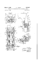
- FIGURE 1 is a top plan view showing a section of model railroad track including an actuating device constructed in accordance with the present invention, and illustrating in dashed outline, and in dot-and-dashed outline certain positions of a car mechanism to be operated by the actuating device;
- FIGURE 2 is an enlarged top plan view showing a portion of the actuating device of FIGURE 1 apart from the railroad track;
- FIGURE 3 is a transverse, sectional elevational view taken substantially along the line 33 of FIGURE 1, illustrating a hopper car in position on the track, the hopper car being partly broken away for clarity of understanding, and showing a portion of the car mechanism in an alternate position in dot-and-dash outline;
- FIGURE 4 is a partial side elevational view, taken substantially along the line 44 of FIGURE 3, partly broken away for clarity of understanding;
- FIGURE 5 is an enlarged, fragmentary end view of the actuating device of FIGURE 2, illustrating the position of a coupled striker pin in solid line, and a free or uncoupled striker pin in dot-and-dash outline;
- FIGURE 6 is a sectional elevational view taken substantially along the line 6-6 of FIGURE 2;
- FIGURE 7 is a bottom plan view showing a hopper car constructed in accordance with the teachings of the resent invention.
- FIGURE 8 is a side elevational view showing a hopper car having a coupler, and a cam construction of the present invention, all in operative relation with a railroad track.
- a section of model railroad track is there generally designated 10, and includes a pair of longitudinally extending, parallel, laterally spaced track rails 11, and a plurality of laterally extending ties 12. It will be observed that the ties 12 are spaced apart a considerably greater than normal distance in the track region 13. Interposed between the track rails 11, in the track region 13, is a device for actuating the mechanism of a passing model railroad car, which device is generally designated 15.
- the actuating device 15 is of open, generally rectangular configuration in the plan view of FIGURE 1, including a pair of parallel spaced side pieces or cam members 16 extending longitudinally of the track 10, located in spaced relation between the rails thereof, and a pair of laterally or transversely extending end pieces 17 re spectively seated on rail ties 12 and preferably fixed thereto, as by fasteners 18.
- a pair of spaced feet 19 extend laterally outward from each side piece or cam member 16 to engage with the adjacent rail 11, and thus locate the actuating device 15 symmetrically in spaced relation between the rails.
- each of the cam members 16 extends longitudinally of and in spaced relation between the track rails 11, being located laterally offset from the center line of the track 10; and further, that the cam members 16 are located symmetrically on opposite sides of the track center line, each adjacent to and spaced from a respective rail 11.
- Each of the side pieces or cam members 16 includes a longitudinally extending lower portion 21, and a longitudinally extending upper portion 22, superposed on the lower portion.
- each upper cam-member portion 22 has its inner side or surface in vertical alignment or flush with the inner side or surface of the associated lower cam-member portion to define a generally vertical inner wall or surface of the respective cam member.
- each upper cammember portion has a vertical outer surface 24 offset laterally inward from the vertical outer surface 25 of the adjacent nether cam-member portion 21.
- each lower cam-member portion 21 is provided with an upper surface 26 extending between the upper edge of surface 25 and lower edge of surface 24- and inclined laterally inward.
- each surface 2d extends laterally inward and upward from its adjacent surface 25 to its adjacent surface 24.
- Each upper cam-member portion 22 is also provided with an upper surface 27, which surface extends from the upper horizontally extending rounded edge 28 at an intersection With the vertical outer surface 24, laterally inward and downward to intersect with the inner surface 23. That is, each upper surface 27 declines laterally inward from the upper edge of the outer surface 24 to the upper edge of the adjacent inner surface 23.
- the locating feet 19 are seen in FIGURE 3 as being spaced below the upper flanges of rails 11.
- each of the longitudinally extending upper cam-member portions 22 has its opposite end portions of outwardly tapering configuration, or of laterally decreasing dimensions in the longitudinally outward direction. More specifically, each of the outer surfaces 24 has its opposite end portions 30 bent to extend obliquely laterally inward, in the longi tudinally outward direction, terminating in a generally vertical end edge 31.
- the end regions 39 of the vertical cam-member surface 24 may be considered as converging toward their adjacent inner cam-member surfaces 23, and terminating at an intersection with the latter surfaces defined by the vertical end edges 31.
- the upper end regions 32 of the horizontal upper edges 22 of the surfaces 24 remain coplanar with their intermediate portions and extend laterally, obliquely inward terminating at the end edges 31.
- the end portions 33 of the upper inclined surfaces 27 also extend obliquely, laterally inward, so as to intersect with the horizontal upper edge portions 32. Further, the end portions 34 of the surfaces 26 extend laterally inward to intersect with their adjacent oblique surface portions 30 along a line of increasing elevation toward the end edge 31, as seen at 35 in FIGURE 4.
- each extension 38 is bounded by vertically disposed outer and inner side walls 39 and 40, respectively extending from the vertical side walls 25 and 23, and converging or tapering to an intersection at 41. That is, in the illustrated embodiment, the outer side Wall 39 extends obliquely longitudinally inward, and the inner side wall 40 extends obliquely, longitudinally outward to their intersection point.
- each side-piece extension 38 is provided with an upper wall or surface 44 which extends longitudinally outward from the adjacent end portion 34 of the adjacent upper surface 26, between and intersecting with the side walls or surfaces 39 and 40 along respective edges for lines of intersection at 42 and 43.
- the upper surface 44 is inclined upwardly and laterally inward, in a manner similar to the upper surface 26, and is also inclined in the longitudinal direction, downward and outward, so that its lines of intersection 42 and 43 with the vertical surfaces 39 and 40 converge in the longitudinally outward direction (best seen in FIGURE 2), and decline the longitudinally outward direction toward their intersection 41 (as may be seen in FIGURES 4, 5, and 6).
- the surface 40 of extension 38 may be considered as laterally inward of the extension surface 44.
- intersection or edge 43 Adjacent to the end edge or leading end 31, it will be observed that an approximately triangular generally horizontal surface 45 is formed on each extension 38, which surface intersects with the surfaces 40 and 44. Further, one end, the longitudinally inward end of the intersection line or edge 43 terminates at the horizontal surface or flat 45. As may be seen in FIGURE 4, the intersection or edge 43 extends from its longitudinally inward end at the surface 45, at an elevation above that of the track rails 11, and declines longitudinally outward to its termination at 41, at an elevation below that of the upper rail surface.
- the end pieces 17 may be substantially flat, each extending between an adjacent pair of extensions 38 and fixedly secured thereto or formed integral therewith. Further, the upper surfaces of the end pieces 17 are necessarily at a sufficiently low elevation to avoid obstructing any rolling equipment.
- the depending striker pin 43 of a conventional car coupler is illustrated in FIGURE 5, being shown in solid lines in its coupled condition, located laterally inward of the cam member 16, and in its free or uncoupled condition in dot-and-dash outline.
- the lower end of the striker pin 48 is at an elevation between the lower outer end 41 of the intersection line 43, and the upper inner end of the latter.
- the upper inner end of the edge or line 43, adjacent to the surface 45 is at an elevation above the maximum permissible or allowable elevation of the lower striker-pin end within manufacturing tolerances, while the lower, outer end of the line or edge 43 is at an elevation less than the lowest permissible or allowable elevation of the depending strikerpin end Within manufacturing tolerances.
- a striker pin of the car in coupled condition will pass laterally inward of and between the cam members 16. Even if the position of a striker pin in coupled condition exceeds lateral permissible limits, it will engage with and be directed inward by the obliquely extending, vertical surface 46* or its upper edge 43, for passage between the cam members 16.
- a coupler striker pin in free or uncoupled condition is not accurately predictable, as the couplers are necessarily afforded appreciable swinging movement.
- the striker pin of a free coupler may then pass between the cam members 16, should its striker pin engage with the laterally inner surface 40 or the inner side of its upper edge 43, in the manner described hereinbefore in connection with couplers in coupled condition. If the depending striker-pin end of a coupler in free or uncoupled condition should engage with the upper or outer surface 44, it will be directed laterally outward by such surface, probably into engagement with the vertically disposed, obliquely extending surface 30, and thence along the vertical surface 24.
- a coupler striking pin is directed out of or away from abutting engagement with the leading end or edge 31 for smooth and free passage along the actuating device 15.
- FIGURES 3, 4, and 7 are shown portions of a model railroad car, generally designated 50, of the hopper type. That is, the car 56 includes a body shaped to include one or more hoppers 51 adapted to contain fluent material, and each formed with a downwardly opening outlet 52 for the fluent material. Each outlet 52 is defined between a pair of forwardly and rearwardly spaced, generally vertical walls, and a pair of laterally spaced downwardly convergent side walls 54.
- the vertical walls 53 terminate in forwardly and rearwardly spaced relation, and the side walls 54 terminate in laterally spaced relation, to define therebetween an outlet opening.
- each of the lower wall edges 56 is of a double, arcuately convex configuration, for purposes appearing presently.
- each hopper outlet 53 Mounted exteriorly of and beneath each hopper outlet 53 are a pair of movable closure gates 66.
- the gates 60 are disposed in side-by-side relation, each including a bottom plate or sheet 61, of laterally, downwardly bowed or arcuate configuration disposed at least partially beneath the opening of outlet 52.
- a pair of hanger arms 62 extend upward from opposite forward and rearward ends of each plate 61, being pivotally connected at their upper ends, as by generally horizontal, forwardly extending pivot means 63, for swinging movement between the lower, closed position (shown in solid lines), and the outer, open position (shown in dot-and-dash outline).
- the gates 60 are swingable toward each other to dispose their bottom plates 61 beneath the outlet 52 to close the latter, and are swingableaway from each other to open the outlet.
- the inner, upwardly concave surfaces of the plates 61 are configured to conform with the edges 56; and, the center of curvature of each plate 61 is preferably concentric with its respective pivot means 63, or located laterally outward thereof.
- the gates are constructed such that their center of gravity tends to maintain the gates closed, or move the gates toward each other about their pivotal axes. Also, the frictional resistance of fluent material in the hopper against the hopper and gate surfaces tends to maintain the gates closed.
- each gate plate 61 On the underside of each gate plate 61, depending therebelow, is a cam follower 65 having an inwardly pointing generally V-shaped surface 66 approximately normal to the underside of the adjacent plate 61.
- the depending cam followers 65 are laterally spaced from each other to leave an open central region.
- the undersurfaces of the plates 61 are spaced above the top of the cam members 16, as defined by the upper edges 28 and 32; however, the followers 65 depend below the edges 28 and 32 for engagement with the cam members as the car 50 passes over the actuating device 15.
- a cam follower 65 with its gate in closed condition is schematically illustrated in dashed outline in FIGURE 1.
- one surface portion 30 of the cam member 16 engages with the surface 66 of the cam follower, the latter riding on the former, to shift the cam follower laterally outward, to the position schematically illustrated in dot-and-dash outline, in which the gate 60 is open.
- the surfaces 24 and 30 of each cam member serve as cam surfaces actuating the gates 66 to move toward their open positions.
- the cams 65 pass beyond either end of the cam members 16, they return by gravity to their closed-gate positions.
- the hopper car 50 would be moved on the track to position one hopper 51 over the actuating device 15, thereby opening the so-positioned hopper and permitting the discharge therefrom of fluent material.
- the material discharged will pass between the cam members 16, or between a cam member and the adjacent rail 11, the inclined surfaces 22 and 24 efiectively insuring that substantially all of the fluent material passes below the track.
- the present invention provides a car mechanism, defined by the gates 60, and actuating means therefor, defined by the device 15, which fully accomplish their intended objects and are well adapted to meet practical conditions of manufacture and use.
- a wheeled model railroad car having its wheels rollable along the rails of said track, a mechanism on said car operable from the underside thereof, and a swingable car coupler on one end of said car having a depending striker pin; device for actuating said mechanism from the underside thereof without adversely affecting the car couplers, said device comprising an upstanding cam located between the rails having one end positioned for possible interfering abutment with the striker pin and offset from the center line of said track sufliciently to permit the striker pin of a coupled railroad car on said track to pass laterally inward of said cam and the striker pin of an uncoupled car to pass optionally laterally inward and outward of said cam, said cam being configured to actuate the mechanism of the passing railroad car, and an extension projecting away from said one cam end longitudinally of said track, said extension including a pair of upwardly convergent surfaces intersecting along a line extending in the direction away from said one
- a device wherein the laterally inner one of said surfaces is generally vertical and extends in a direction away from said cam generally obliquely toward the adjacent track rail.
- a device said cam being provided with a mechanism-actuating surface extending in the direction away from said intersection line generally obliquely with respect to said track.
- a wheeled model railroad car having a downwardly opening outlet for fluent material, a swingable coupler at one end of said ca'r having a depending striker pin, a gate mounted on said car for movement between positions opening and closing said outlet and yieldably urged toward its closing position, and a pair of track rails rollably supporting said car for movement along said rails;
- the improvement comprising a cam mounted in the space between said rails adjacent to and spaced from one of said rails and positioned for possible interfering abutment with the striker pin of a car coupler, said cam being configured for operative engagement with said gate to shift the latter to its outlet-opening position upon movement of said car over said cam, and an extension projecting from said cam longitudinally of said track, said extension including a pair of upwardly convergent surfaces intersecting along a line extending in the direction away from said cam and declining from an elevation above the maximum permissible elevation of the depending end of said striker pin to an elevation below the minimum permissible elevation of the depending striker-pin end
Description
Priority Applications (1)
| Application Number | Priority Date | Filing Date | Title |
|---|---|---|---|
| US707578A US3024924A (en) | 1958-01-07 | 1958-01-07 | Railroad car hopper gate and coupler cam actuating means |
Applications Claiming Priority (1)
| Application Number | Priority Date | Filing Date | Title |
|---|---|---|---|
| US707578A US3024924A (en) | 1958-01-07 | 1958-01-07 | Railroad car hopper gate and coupler cam actuating means |
Publications (1)
| Publication Number | Publication Date |
|---|---|
| US3024924A true US3024924A (en) | 1962-03-13 |
Family
ID=24842259
Family Applications (1)
| Application Number | Title | Priority Date | Filing Date |
|---|---|---|---|
| US707578A Expired - Lifetime US3024924A (en) | 1958-01-07 | 1958-01-07 | Railroad car hopper gate and coupler cam actuating means |
Country Status (1)
| Country | Link |
|---|---|
| US (1) | US3024924A (en) |
Cited By (4)
| Publication number | Priority date | Publication date | Assignee | Title |
|---|---|---|---|---|
| US3134489A (en) * | 1961-12-11 | 1964-05-26 | Phillip J Gillham | Automatic uncoupling ramp as for miniature railroad cars |
| US3227100A (en) * | 1963-05-01 | 1966-01-04 | Jay R Sheesley | Hopper car door actuating mechanism |
| US3316858A (en) * | 1962-10-24 | 1967-05-02 | Union Tank Car Co | Railway hopper car closure actuating device |
| US4102448A (en) * | 1972-04-10 | 1978-07-25 | S I Handling Systems, Inc. | Conveying apparatus including tilting support structures |
Citations (18)
| Publication number | Priority date | Publication date | Assignee | Title |
|---|---|---|---|---|
| US528279A (en) * | 1894-10-30 | Dump-car | ||
| US958207A (en) * | 1908-05-08 | 1910-05-17 | Lamson Cons Store Service Co | Cable-carrier apparatus. |
| US986264A (en) * | 1910-01-27 | 1911-03-07 | James Lewis Blaker | Means for automatically restoring cars after being dumped. |
| US1050240A (en) * | 1909-06-07 | 1913-01-14 | Nat Dump Car Co | Dump-car. |
| US1138950A (en) * | 1914-03-06 | 1915-05-11 | Ray Henderson | Live-stock feeder. |
| US1153146A (en) * | 1914-01-05 | 1915-09-07 | B E Willis | Drop-door mechanism. |
| US1213327A (en) * | 1916-08-25 | 1917-01-23 | James H Baker | Automatic car-dumping appliance. |
| US1312465A (en) * | 1919-08-05 | Rolling-stock | ||
| US1594863A (en) * | 1926-02-05 | 1926-08-03 | R H Beaumont Co | Tram-car equipment |
| US1746103A (en) * | 1928-06-30 | 1930-02-04 | Beulan E Cheely | Dump car |
| US1897362A (en) * | 1931-06-17 | 1933-02-14 | Daniels William George | Toy train draft coupling |
| US2042266A (en) * | 1931-08-12 | 1936-05-26 | Hugh W Sanford | Mine car |
| US2261258A (en) * | 1939-06-30 | 1941-11-04 | George G Kinnear | Automatic coupler for toy or model railroad cars |
| US2558383A (en) * | 1945-12-04 | 1951-06-26 | Pritchard Sydney Charles | Automatic coupling for model railway rolling stock |
| US2617541A (en) * | 1949-02-11 | 1952-11-11 | Ronald B Goode | Miniature coupler |
| US2631740A (en) * | 1949-03-25 | 1953-03-17 | Ralph L Watson | Coupler for model railroads |
| CH318862A (en) * | 1953-06-23 | 1957-01-31 | Meccano Limited | Disconnecting device for model railway tracks |
| US2872051A (en) * | 1957-06-06 | 1959-02-03 | Kusan Inc | Automatic coupling and uncoupling means for miniature trains |
-
1958
- 1958-01-07 US US707578A patent/US3024924A/en not_active Expired - Lifetime
Patent Citations (18)
| Publication number | Priority date | Publication date | Assignee | Title |
|---|---|---|---|---|
| US528279A (en) * | 1894-10-30 | Dump-car | ||
| US1312465A (en) * | 1919-08-05 | Rolling-stock | ||
| US958207A (en) * | 1908-05-08 | 1910-05-17 | Lamson Cons Store Service Co | Cable-carrier apparatus. |
| US1050240A (en) * | 1909-06-07 | 1913-01-14 | Nat Dump Car Co | Dump-car. |
| US986264A (en) * | 1910-01-27 | 1911-03-07 | James Lewis Blaker | Means for automatically restoring cars after being dumped. |
| US1153146A (en) * | 1914-01-05 | 1915-09-07 | B E Willis | Drop-door mechanism. |
| US1138950A (en) * | 1914-03-06 | 1915-05-11 | Ray Henderson | Live-stock feeder. |
| US1213327A (en) * | 1916-08-25 | 1917-01-23 | James H Baker | Automatic car-dumping appliance. |
| US1594863A (en) * | 1926-02-05 | 1926-08-03 | R H Beaumont Co | Tram-car equipment |
| US1746103A (en) * | 1928-06-30 | 1930-02-04 | Beulan E Cheely | Dump car |
| US1897362A (en) * | 1931-06-17 | 1933-02-14 | Daniels William George | Toy train draft coupling |
| US2042266A (en) * | 1931-08-12 | 1936-05-26 | Hugh W Sanford | Mine car |
| US2261258A (en) * | 1939-06-30 | 1941-11-04 | George G Kinnear | Automatic coupler for toy or model railroad cars |
| US2558383A (en) * | 1945-12-04 | 1951-06-26 | Pritchard Sydney Charles | Automatic coupling for model railway rolling stock |
| US2617541A (en) * | 1949-02-11 | 1952-11-11 | Ronald B Goode | Miniature coupler |
| US2631740A (en) * | 1949-03-25 | 1953-03-17 | Ralph L Watson | Coupler for model railroads |
| CH318862A (en) * | 1953-06-23 | 1957-01-31 | Meccano Limited | Disconnecting device for model railway tracks |
| US2872051A (en) * | 1957-06-06 | 1959-02-03 | Kusan Inc | Automatic coupling and uncoupling means for miniature trains |
Cited By (4)
| Publication number | Priority date | Publication date | Assignee | Title |
|---|---|---|---|---|
| US3134489A (en) * | 1961-12-11 | 1964-05-26 | Phillip J Gillham | Automatic uncoupling ramp as for miniature railroad cars |
| US3316858A (en) * | 1962-10-24 | 1967-05-02 | Union Tank Car Co | Railway hopper car closure actuating device |
| US3227100A (en) * | 1963-05-01 | 1966-01-04 | Jay R Sheesley | Hopper car door actuating mechanism |
| US4102448A (en) * | 1972-04-10 | 1978-07-25 | S I Handling Systems, Inc. | Conveying apparatus including tilting support structures |
Similar Documents
| Publication | Publication Date | Title |
|---|---|---|
| US3024924A (en) | Railroad car hopper gate and coupler cam actuating means | |
| US3344748A (en) | Hopper car discharge outlet assembly | |
| US3509828A (en) | Railway hopper car gate outlet | |
| US2070045A (en) | Railway hopper car construction | |
| US2829246A (en) | Derail | |
| US2036198A (en) | Spring frog | |
| US938976A (en) | Dump-car. | |
| US2235555A (en) | Horizontally floating car coupler | |
| US2043616A (en) | Railway car | |
| US2591924A (en) | Method of manufacturing hopper car frame structure | |
| US1474814A (en) | Hopper car | |
| US2901985A (en) | Hopper door latching mechanism | |
| US1388388A (en) | Automatic car-dump mechanism | |
| US1400867A (en) | Dumping-car | |
| US2741192A (en) | Sliding closure for discharge outlet | |
| US1733736A (en) | Car-door mechanism | |
| US2076005A (en) | Bottom dump apparatus with sloping discharge walls | |
| US2225462A (en) | Drop-bottom mine car | |
| US1462190A (en) | Car coupler | |
| US3100455A (en) | Latching device for railway hopper car doors | |
| US1869029A (en) | Door | |
| US2559760A (en) | Hopper car door frame | |
| US1968511A (en) | Railway car | |
| US2281393A (en) | Self-unloading toy vehicle | |
| US1853170A (en) | Railway car construction |
Legal Events
| Date | Code | Title | Description |
|---|---|---|---|
| AS | Assignment |
Owner name: TYCO INDUSTRIES, INC. Free format text: CHANGE OF NAME;ASSIGNOR:TYCO INDUSTRIES, INC.;REEL/FRAME:003973/0005 Effective date: 19811217 Owner name: TYCO INDUSTRIES, INC. Free format text: CHANGE OF NAME;ASSIGNOR:SAVOY-MALLORY JOINT VENTURE, INC.;REEL/FRAME:003973/0009 Effective date: 19811217 Owner name: CONGRESS FINANCIAL CORPORATION Free format text: SECURITY INTEREST;ASSIGNOR:SAVOY-MALLORY JOINT VENTURE, INC.;REEL/FRAME:003973/0013 Effective date: 19810723 Owner name: SAVOY-MALLORY JOINT VENTURE, INC., 540 GLEN AVE., Free format text: ASSIGNMENT OF ASSIGNORS INTEREST.;ASSIGNOR:TYCO INDUSTRIES, INC.;REEL/FRAME:003973/0032 Effective date: 19810723 Owner name: TYCO INDUSTRIES, INC., NEW YORK Free format text: CHANGE OF NAME;ASSIGNOR:TYCO INDUSTRIES, INC.;REEL/FRAME:003973/0005 Effective date: 19811217 Owner name: TYCO INDUSTRIES, INC., NEW YORK Free format text: CHANGE OF NAME;ASSIGNOR:SAVOY-MALLORY JOINT VENTURE, INC.;REEL/FRAME:003973/0009 Effective date: 19811217 Owner name: CONGRESS FINANCIAL CORPORATION, NEW YORK Free format text: SECURITY INTEREST;ASSIGNOR:SAVOY-MALLORY JOINT VENTURE, INC.;REEL/FRAME:003973/0013 Effective date: 19810723 |
|
| AS | Assignment |
Owner name: TYCO INDUSTRIES, INC. Free format text: ASSIGNMENT OF ASSIGNORS INTEREST.;ASSIGNOR:CONGRESS FINANCIAL CORPORATION;REEL/FRAME:004831/0332 Effective date: 19870806 Owner name: TYCO INDUSTRIES, INC.,STATELESS Free format text: ASSIGNMENT OF ASSIGNORS INTEREST;ASSIGNOR:CONGRESS FINANCIAL CORPORATION;REEL/FRAME:004831/0332 Effective date: 19870806 |
|
| AS | Assignment |
Owner name: TYCO INDUSTRIES, INC. Free format text: RELEASED BY SECURED PARTY;ASSIGNOR:CONGRESS FINANCIAL CORPORATION;REEL/FRAME:004993/0892 Effective date: 19881201 |