US3076216A - Convertible retractible sponge mop - Google Patents
Convertible retractible sponge mop Download PDFInfo
- Publication number
- US3076216A US3076216A US836118A US83611859A US3076216A US 3076216 A US3076216 A US 3076216A US 836118 A US836118 A US 836118A US 83611859 A US83611859 A US 83611859A US 3076216 A US3076216 A US 3076216A
- Authority
- US
- United States
- Prior art keywords
- sponge
- handle
- head
- mop
- shank
- Prior art date
- Legal status (The legal status is an assumption and is not a legal conclusion. Google has not performed a legal analysis and makes no representation as to the accuracy of the status listed.)
- Expired - Lifetime
Links
Images

Classifications
-
- A—HUMAN NECESSITIES
- A47—FURNITURE; DOMESTIC ARTICLES OR APPLIANCES; COFFEE MILLS; SPICE MILLS; SUCTION CLEANERS IN GENERAL
- A47L—DOMESTIC WASHING OR CLEANING; SUCTION CLEANERS IN GENERAL
- A47L13/00—Implements for cleaning floors, carpets, furniture, walls, or wall coverings
- A47L13/10—Scrubbing; Scouring; Cleaning; Polishing
- A47L13/14—Scrubbing; Scouring; Cleaning; Polishing combined with squeezing or wringing devices
Definitions
- This invention relates to an implement adapted for use as a mop-like cleaning device and which includes an attachment which renders the implement usable or adaptable as a squeegee or as an implement for applying wax or other material, or as a brushing implement.
- the main objects of this invention are:
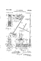
- FIG. 1 is a perspective view of an implement embodying the invention with the mop or cleaning element in use position.
- FIG. 2 is an elevational view thereof viewed endwise of the head or body member, a portion of the inner handle member being broken away.
- FIG. 3 is an enlarged fragmentary view with the handle broken away.
- FIG. 4 is an enlarged fragmentary view mainly in longitudinal section on a line corresponding to line 44 of FIG. 3.
- FIG. 5 is a fragmentary view mainly in section on a line corresponding to line 5-5 of FIG. 4 with the mop element in retracted or waxing position.
- FIG. 6 is a fragmentary inverted View of the head member.
- FIG. 7 is a perspective view of the mop element supporting bar.
- FIG. 8 is a perspective view of the mop element.
- FIG. 9 is a fragmentary perspective view of the mop element guard or shield.
- FIG. 10 is a fragmentary perspective view of the implement adapted for use as an applicator with materials such, for example, as wax, that is, for use in waxing surfaces.
- FIG. 11 is an end elevational view of the embodiment of adaptation shown in FIG. 10.
- FIG. 12 is an end elevational view adapting the implement for use as a brush either as an applicator or for cleaning.
- FIG. 13 is a fragmentary elevational view corresponding to FIGS. 11 and 12 showing the implement adapted for use as a squeegee.
- FIG. 14 is a fragmentary view of a modified form or embodiment of the invention including an adjustable stop which in one position permits reciprocating movement of the handle members relative to each other and in another position prevents such relative movement.
- FIG. 15 is an enlarged cross sectional view on line 15-15 of FIG. 14.
- FIGS. 1 to 9 inclusive illustrate the invention as adapted for use as a mop or other surface cleaning implement
- FIGS. 10 to 13 inclusive illustrate other embodiments or adaptations for applying the wax or other material to a surface, as a brush or as a squeegee for use, for example, after the device has been used for cleaning windows or wall surfaces.
- the embodiment illustrated comprises a head member designated generally by the numeral 1 which is of outwardly facing channel cross section, the side members 2 desirably diverge slightly in outward direction and terminate in outwardly diverging flange like portions 3, these being desirably curved and curvedly merging into the side members 2.
- this head member is formed as a sheet metal stamping.
- the handle comprises the tubular inner handle member 4 which is provided with laterally projecting lugs 5 at its inner end projecting through slots 6 provided therefor in the top 7 of the head member and turned outwardly and fixedly secured there-to as by spot welding, indicated at 8 in FIG. 4.
- the head member is reinforced by the disc 9 which is spot welded thereto, as indicated in FIG. 4.
- the outer handle member it ⁇ is slidable and rotatable in the inner handle member and is provided with a nut 11.
- the mop or cleaning element 12 is desirably formed of synthetic cellulose sponge like material and has upwardly projecting upwardly diverging work faces 13 and downwardly diverging top surfaces 14, see FIGS. 1, 2, 3 and 8. However if should be understood that this element 12 may be of substantially varied cross-sectional shape.
- the element 12 is provided with a downwardly extending longitudinal slot 15 preferably extending about one-half the way through the member 12, as shown in FIG. 3.
- the rod like supporting bar 16 is disposed in this slot as is illustrated in the drawing and is provided with a shank or stem 17 disposed centrally thereof and projecting through holes 18 provided therefor and desirably fittingly receiving the upper end of the shank which is threaded to receive the nut H, the nut being engaged and disengaged from the shank by rotating movement of the outer handle member 1%.
- This permits rapid assembly and disassembly of the element 12 with its related parts and the shank or stem is always properly located to receive the nut when inserted in the holes 18.
- the shield or support member 29 is provided, this being desirably formed of thermo-plastic material and of such width that when in operable relation it projects between the flanges 3 on the head member arms and the member 12.
- the member 20 is provided with transverse ribs 21 on its upper surface which are in thrust supported and sliding engagement with the sides of the head member, as is illustrated.
- the member 29 also serves as a squeeze member for the element 12, as is best illustrated in FIG. 5.
- the part or shank 17 is first inserted through the sponge mop element 12 followed by rod 16 following in slot 15 until rod 16 is embedded substantially along the longitudinal center line of element 12.
- the support member is then dropped on element 12 with part 17 extending upwardly through a central hole 36 therein as shown.
- the mop assembly is then applied to the head member by inserting part 17 up through the holes 18 until member 20 lies in the mouth of the channel between side members 2.
- the handle 19 is then inserted into tubular handle 4 and nut 11 threaded onto the upper end of part 17 by turning of handle 10 relative to the head member 1.
- FIGURES 10 and 11 illustrate an adaptation of the invention as a waxing device or as an applicator for wax or other materials.
- This adaptation includes the body member 22 which is of transversely curved cross section and is provided with inwardly facing grooves 23 and 24 engageable with the edges of the outturned portions 3 of the head member, the coengaging parts being springable so that there is, in effect, a snap on or spring engagement.
- the member 22 is provided with a flange like finger piece 30 which facilitates the engagement and disengagement thereof.
- the member 12 is provided with a facing 25 of nap like or fibrous material, as is best illustrated in FIG. 11, which is highly practical in the application of wax and other material to a surface.
- the member 22 is provided with a facing 26 having bristles or brush like filaments 27.
- the member 22 is provided with a facing 28 having longitudinally extending laterally spaced blade like members 29 which adapts the implement for use as a squeegee for wiping windows, walls and other surfaces.
- the adaptation of the implement for these various hereinbefore stated uses may be very quickly made and with little effort.
- an outer handle member 37 with a sleeve-like stop member 31 which is provided with an inwardly projecting lug 32 which is engaged in the slot 33 extending longitudinally of the handle member 37 and having an offset 34 at its upper end and an offset 35 at its lower end.
- This stop member is retractable upon and adjustable longitudinally of the handle member 37 and desirably frictionally engages the outer handle member so that it is maintained in its adjusted position therein.
- a transversely elongated synthetic sponge adapted to rest on the floor during wet mopping operations, a bar extending longitudinally within said sponge and having a shank extending upwardly through the sponge, a handle secured to said shank and extending upwardly for manipulation of the sponge in floor mopping action by a standing operator, a head carried by said handle and having spaced walls engaging opposite portions of said sponge and supporting the same rigidly during mopping action, means to extend said head upon said handle to thereby draw said sponge upwardly between said spaced walls to wring the sponge, and unexposed abutment means between said head and said handle to maintain said spaced walls in support of said sponge during mopping action.
- a transversely elongated synthetic sponge adapted to rest on the floor during wet mopping operations, a bar extending longitudinally within said sponge and having a shank extending upwardly through the sponge, a handle secured to said shank and extending upwardly for manipulation of the sponge in floor mopping action by a standing operator, a head carried by said handle and having spaced walls engaging opposite portions of said sponge and supporting the same rigidly during mopping action, means to extend said head upon said handle to thereby draw said sponge upwardly between said spaced walls to wring the sponge, abutment means between said head and said handle to maintain said spaced walls in support of said sponge during mopping action, and additional support means carried by and overlapping said sponge between the same and said spaced walls to apply downward and forward mopping pressures to the sponge during actuation of the same.
- an elongated head member of downwardly facing channel section including a top and spaced side members, said head member having longitudinal spaced transverse slots in the top thereof, a reinforcing disc secured to the inner side of said top between said slots therein, said top and disc having aligned openings therein, an inner handle member provided with lugs projecting through said slots and fixedly secured to the inner side of the top, an outer handle member slidable within said inner handle member and having a nut fixedly connected to its inner end, a springably resilient cellular mop element having top surfaces supportedly coacting with said side members of said head member when the mop element is in its projected use position, said mop element having a downwardly opening longitudinal slot therein, a supporting bar for said mop element disposed in said slot in said mop element and provided with a shank projecting upwardly therefrom and guidingly disposed through said opening in said head member top and its said reinforcing disc, said shank being threaded at its
- an elongated head member of downwardly facing channel section and including a top and spaced side members a handle comprising an inner handle member fixedly connected to said head member centrally thereof and an outer handle member slidable within said inner handle member and having a nut fixedly connected to its inner end, a springably resilient mop element supportedly coacting with said side members of said head member when the mop element is in its projected use position, and a supporting bar for said mop element disposed therein and provided with a shank projecting upwardly therefrom and having a threaded portion at its outer end, said head member top having an opening reciprocatingly and guidingly receiving said shank for aligning it to receive said nut on said outer handle member, said shank being freely movable through said opening as when said inner handle member is extended downwardly from said outer handle member to draw said mop element into said channel for squeezing water from said element and the top of said channel providing an abutment to limit the downward movement of said outer handle
- an elongated head member of downwardly facing channel section and including a top and spaced side members a handle comprising an inner handle member fixedly connected to said head member centrally thereof and an outer handle member slidable within said inner handle member and having a nut fixedly connected to its inner end, the springably resilient mop element supportedly coacting with said side members of said head member when the mop element is in its projected use position, and a supporting bar for said mop element disposed therein and provided with a shank projecting upwardly therefrom and into the inner end of said inner handle member and having a threaded portion at its outer end to receive said nut, said shank being freely movable through said opening as when said inner handle member is extended downwardly from said outer handle member to draw said mop element into said channel for squeezing water from said element and the top of said channel providing an abutment to limit the downward movement of said outer handle relative to said channel and transmit thrust from said outer handle through said channel side members to the sponge
- a device of the class described the combination of an elongated head member of outwardly facing channel section, an inner handle member fixedly connected to said head member, an outer handle member telescopingly associated with said inner handle member, a resiliently collapsible work element operatively connected to said outer handle member and adapted to be retractably collapsed within said head member or to be projected therefrom to use position by the reciprocating adjustment of said handle members relative to each other, and a stop member mounted upon and adjustably positionable upon said outer handle member to provide in one position of adjustment for free reciprocation of the handle members relative to each other to retract said work element into said head member or to project it therefrom and in another position of adjustment to engage the inner handle member to prevent such reciprocating movement of the handle members relative to each other with the work member in its retracted position.
- a device of the class dmcribed the combination of an elongated head member of outwardly facing channel section, an inner tubular handle member fixedly connected to said head member, an outer handle member telescopingly carried within said inner handle member and extending upwardly therefrom to be gripped by the hand of a standing.
- a resiliently collapsible work element operatively connected to the lower end of said outer handle member and adapted to be retractably collapsed within said head member or to be projected therefrom to use position by the reciprocating adjustment of said handle members relative to each other, and a stop member mounted upon one of said handle members adjustably positionable to provide in one position of adjustment for reciprocation of the handle members relative to each other to retract said work element into said head member or to project it therefrom and in an other position of adjustment for engagement with complemental stop means on the other handle member to prevent such reciprocating movement of the handle members relative to each other with the work member in its retracted position.
- a device of the class described the combination of an elongated head member of downwardly facing channel section the side members of which terminate in outwardly flared edge portions, a handle rigidly secured to said head member to reciprocate the same in operation, a sponge block disposed at the mouth of said channel and normally larger than the channel to effectivly seat against said flared edge portions of the channel, said channel being constructed to receive the entire sponge block therein, means extending upwardly through said handle to withdraw said sponge block into said channel for squeezing purposes and to extend the same to operative position seated against said flared edges, and a removable work member adapted to bridge the mouth of said channel and having inwardly facing grooves receiving the flared edges of said channel member and resiliently tensioning the sides of the channel to secure the work member in operative position upon said head channel.
Description
Feb. 5, 1963 H. A. ANDERSON 3,076,216
CONVERTIBLE RETRACTIBLE SPONGE MOP Filed Au 26, 1959 '2 Sheets-Sheet 1 JNVEN TOR.
A T TO R N15 1 w /m mamww fi H. A. ANDERSON CONVERTIBLE RETRACTIBLE SPONGE MOP Feb. 5, 1963 2 Sheets-Sheet 2 Filed Aug. 26, 1959 lull I ll @AQQ MQ ATTORNEY.
United States Patent Ofifice 3,076,216 Patented Feb. 5, 1963 3,076,216 CONVERTIBLE RETRACTIBLE SPDNGE MG? Howard A. Anderson, Pittsburgh, Pa, assignor to Bissell, Inc, Grand Rapids, Mich. Filed Aug. 26, 1959, Ser. No. 836,118 11 Claims. (Cl. 15-116) This invention relates to an implement adapted for use as a mop-like cleaning device and which includes an attachment which renders the implement usable or adaptable as a squeegee or as an implement for applying wax or other material, or as a brushing implement.
The main objects of this invention are:
First, to provide a hand manipulated implement which may be quickly and easily adapted for use as a mop or for cleaning of windows or walls and as a squeegee or as an applicator or brush.
Second, to provide a hand manipulated implement having these advantages in which the mop or cleaning element of sponge-like character is effectively supported in use and wear or tearing stresses thereon in use and in wringing operations is minimized.
Third, to provide an apparatus having these advantages which may be quite economically produced, is relatively light in weight in proportion to its size and use capacity and is quickly and easily manipulated for the several uses.
Fourth, to provide an implement having these various advantages in which there are no parts which are likely to pinch or otherwise cause injury to the operator in the manipulation thereof.
Objects relating to details and economies of the invention will appear from the description to follow. The invention is defined and pointed out in the claims.
A preferred embodiment of the invention is illustrated in the accompanying drawing, in which:
FIG. 1 is a perspective view of an implement embodying the invention with the mop or cleaning element in use position.
FIG. 2 is an elevational view thereof viewed endwise of the head or body member, a portion of the inner handle member being broken away.
FIG. 3 is an enlarged fragmentary view with the handle broken away.
FIG. 4 is an enlarged fragmentary view mainly in longitudinal section on a line corresponding to line 44 of FIG. 3.
FIG. 5 is a fragmentary view mainly in section on a line corresponding to line 5-5 of FIG. 4 with the mop element in retracted or waxing position.
FIG. 6 is a fragmentary inverted View of the head member.
FIG. 7 is a perspective view of the mop element supporting bar.
FIG. 8 is a perspective view of the mop element.
FIG. 9 is a fragmentary perspective view of the mop element guard or shield.
FIG. 10 is a fragmentary perspective view of the implement adapted for use as an applicator with materials such, for example, as wax, that is, for use in waxing surfaces.
FIG. 11 is an end elevational view of the embodiment of adaptation shown in FIG. 10.
FIG. 12 is an end elevational view adapting the implement for use as a brush either as an applicator or for cleaning.
FIG. 13 is a fragmentary elevational view corresponding to FIGS. 11 and 12 showing the implement adapted for use as a squeegee.
FIG. 14 is a fragmentary view of a modified form or embodiment of the invention including an adjustable stop which in one position permits reciprocating movement of the handle members relative to each other and in another position prevents such relative movement.
FIG. 15 is an enlarged cross sectional view on line 15-15 of FIG. 14.
FlGS. 1 to 9 inclusive illustrate the invention as adapted for use as a mop or other surface cleaning implement, and FIGS. 10 to 13 inclusive illustrate other embodiments or adaptations for applying the wax or other material to a surface, as a brush or as a squeegee for use, for example, after the device has been used for cleaning windows or wall surfaces.
It should also be understood that the invention of this application is an improvement upon, and in some respects an adaptation of the structure illustrated in the Howard A. Anderson application for patent, Serial No. 771,573, filed November 3, 1958, presently allowed.
The embodiment illustrated comprises a head member designated generally by the numeral 1 which is of outwardly facing channel cross section, the side members 2 desirably diverge slightly in outward direction and terminate in outwardly diverging flange like portions 3, these being desirably curved and curvedly merging into the side members 2. In the embodiment illustrated this head member is formed as a sheet metal stamping. The handle comprises the tubular inner handle member 4 which is provided with laterally projecting lugs 5 at its inner end projecting through slots 6 provided therefor in the top 7 of the head member and turned outwardly and fixedly secured there-to as by spot welding, indicated at 8 in FIG. 4.
Between these lugs the head member is reinforced by the disc 9 which is spot welded thereto, as indicated in FIG. 4. The outer handle member it} is slidable and rotatable in the inner handle member and is provided with a nut 11.
The mop or cleaning element 12 is desirably formed of synthetic cellulose sponge like material and has upwardly projecting upwardly diverging work faces 13 and downwardly diverging top surfaces 14, see FIGS. 1, 2, 3 and 8. However if should be understood that this element 12 may be of substantially varied cross-sectional shape. The element 12 is provided with a downwardly extending longitudinal slot 15 preferably extending about one-half the way through the member 12, as shown in FIG. 3.
The rod like supporting bar 16 is disposed in this slot as is illustrated in the drawing and is provided with a shank or stem 17 disposed centrally thereof and projecting through holes 18 provided therefor and desirably fittingly receiving the upper end of the shank which is threaded to receive the nut H, the nut being engaged and disengaged from the shank by rotating movement of the outer handle member 1%. This permits rapid assembly and disassembly of the element 12 with its related parts and the shank or stem is always properly located to receive the nut when inserted in the holes 18.
To take the wear on this mop element the shield or support member 29 is provided, this being desirably formed of thermo-plastic material and of such width that when in operable relation it projects between the flanges 3 on the head member arms and the member 12.
To minimize friction when the member 12 is retracted into the head member the member 20 is provided with transverse ribs 21 on its upper surface which are in thrust supported and sliding engagement with the sides of the head member, as is illustrated. The member 29 also serves as a squeeze member for the element 12, as is best illustrated in FIG. 5. With this arrangement of parts the mop element can be easily retracted into wringing position as shown in FIG. 5 and the tearing and wear stresses thereon due to this retraction is practically eliminated.
Assembly of the mop of FIGS. 1-9, inclusive is simple. The part or shank 17 is first inserted through the sponge mop element 12 followed by rod 16 following in slot 15 until rod 16 is embedded substantially along the longitudinal center line of element 12. The support member is then dropped on element 12 with part 17 extending upwardly through a central hole 36 therein as shown. The mop assembly is then applied to the head member by inserting part 17 up through the holes 18 until member 20 lies in the mouth of the channel between side members 2. The handle 19 is then inserted into tubular handle 4 and nut 11 threaded onto the upper end of part 17 by turning of handle 10 relative to the head member 1.
In operation, when sponge element 12 has been sufliciently soaked by dipping of the mop into a pail of water or suitable cleaning liquid, the element is moved over a floor by reciprocation of head member 1 with the handle 10. If it is desired to squeeze or wring the mop element 12 dry, the operator merely pulls upwardly on handle 10 with one hand while pushing handle 4 downwardly by the other hand until the sponge element 12 is entirely withdrawn into the channel between side members 2 of head member 1, as shown in FIG. 5. In this operation shield member 2% reduces the friction contact between sponge element 1.2 and the side members 2, and prevents wear and tear of the sponge element.
When handle 13 is reciprocated in a direction to withdraw the mop element .12 into head member 1 the part or shank 17 moves freely through openings 18 and 36, as shown by comparing FIGS. 4 and 5. When handle 10 is in the position of FIGS. 1 to 4, the mop element 12 is supported by shield 26 which in turn engages the flanges 3 on side members 2 to apply the thrust of handle 10 abutting top 7 to the mop element 12 in reciprocating the latter over a floor.
FIGURES 10 and 11 illustrate an adaptation of the invention as a waxing device or as an applicator for wax or other materials. This adaptation includes the body member 22 which is of transversely curved cross section and is provided with inwardly facing grooves 23 and 24 engageable with the edges of the outturned portions 3 of the head member, the coengaging parts being springable so that there is, in effect, a snap on or spring engagement. At one edge the member 22 is provided with a flange like finger piece 30 which facilitates the engagement and disengagement thereof. When the element 12 is in retracted position it in no wise interferes with this attachment.
In FIGURES 10 and 11 the member 12 is provided with a facing 25 of nap like or fibrous material, as is best illustrated in FIG. 11, which is highly practical in the application of wax and other material to a surface. In the embodiment shown in FIG. 12 the member 22 is provided with a facing 26 having bristles or brush like filaments 27. In the embodiment shown in FIG. 13 the member 22 is provided with a facing 28 having longitudinally extending laterally spaced blade like members 29 which adapts the implement for use as a squeegee for wiping windows, walls and other surfaces. The adaptation of the implement for these various hereinbefore stated uses may be very quickly made and with little effort.
In some work or use conditions a substantial thrust may be exerted on the outer handle member in use and the mop 12 might be projected from its retracted position into thrust engagement with one of the devices shown in FIGS. 10, 11, 12 and 13. To prevent this projection I provide an outer handle member 37 with a sleeve-like stop member 31 which is provided with an inwardly projecting lug 32 which is engaged in the slot 33 extending longitudinally of the handle member 37 and having an offset 34 at its upper end and an offset 35 at its lower end. This stop member is retractable upon and adjustable longitudinally of the handle member 37 and desirably frictionally engages the outer handle member so that it is maintained in its adjusted position therein. When adjusted to the position shown in dotted lines in FIG. 14 it coacts with the end of the inner handle member to prevent reciprocating movement of the outer handle member. This holds the outer handle member in its outer position and with the mop element 12 in its retracted position as shown in F168. 5, 10, 11, 12 and 13. The stop is not illustrated in FIGS. 1 and 2 as it is not used in all commercial embodiments and for many uses it is not required, although it is desirable for uses where considerable thrust is required in use and where it is desirable to have the mop element 12 of relatively soft easily compressed material.
It is believed that the foregoing disclosure will enable those skilled in the art to adapt or modify the invention as may be desired.
Having thus described my invention what I claim as new and desire to secure by Letters Patent is:
1. In a floor mop of the class described, a transversely elongated synthetic sponge adapted to rest on the floor during wet mopping operations, a bar extending longitudinally within said sponge and having a shank extending upwardly through the sponge, a handle secured to said shank and extending upwardly for manipulation of the sponge in floor mopping action by a standing operator, a head carried by said handle and having spaced walls engaging opposite portions of said sponge and supporting the same rigidly during mopping action, means to extend said head upon said handle to thereby draw said sponge upwardly between said spaced walls to wring the sponge, and unexposed abutment means between said head and said handle to maintain said spaced walls in support of said sponge during mopping action.
2. In a floor mop of the class described, a transversely elongated synthetic sponge adapted to rest on the floor during wet mopping operations, a bar extending longitudinally within said sponge and having a shank extending upwardly through the sponge, a handle secured to said shank and extending upwardly for manipulation of the sponge in floor mopping action by a standing operator, a head carried by said handle and having spaced walls engaging opposite portions of said sponge and supporting the same rigidly during mopping action, means to extend said head upon said handle to thereby draw said sponge upwardly between said spaced walls to wring the sponge, abutment means between said head and said handle to maintain said spaced walls in support of said sponge during mopping action, and additional support means carried by and overlapping said sponge between the same and said spaced walls to apply downward and forward mopping pressures to the sponge during actuation of the same.
3. The construction of claim 2 in which said additional support means comprises a flexible plastic sheet which at all times confines the upper portion of the sponge against uncontrolled deformation.
4. The construction of claim 3 in which said sheet has ribs thereon engaging said spaced walls and substantially reducing the area of frictional contact between the sheet and said spaced walls during wringing of the sponge.
5. In an implement of the class described, the combination of an elongated head member of downwardly facing channel section and including a top and spaced side members, said head member having longitudinal spaced transverse slots in the top thereof, a reinforcing disc secured to the inner side of said top between said slots therein, said top and disc having aligned openings therein, an inner handle member provided with lugs projecting through said slots and fixedly secured to the inner side of the top, an outer handle member slidable within said inner handle member and having a nut fixedly connected to its inner end, a springably resilient cellular mop element having top surfaces supportedly coacting with said side members of said head member when the mop element is in its projected use position, said mop element having a downwardly opening longitudinal slot therein, a supporting bar for said mop element disposed in said slot in said mop element and provided with a shank projecting upwardly therefrom and guidingly disposed through said opening in said head member top and its said reinforcing disc, said shank being threaded at its outer end to receive said nut on said outer handle member.
6. In an implement of the class described, the combination of an elongated head member of downwardly facing channel section and including a top and spaced side members, a handle comprising an inner handle member fixedly connected to said head member centrally thereof and an outer handle member slidable within said inner handle member and having a nut fixedly connected to its inner end, a springably resilient mop element supportedly coacting with said side members of said head member when the mop element is in its projected use position, and a supporting bar for said mop element disposed therein and provided with a shank projecting upwardly therefrom and having a threaded portion at its outer end, said head member top having an opening reciprocatingly and guidingly receiving said shank for aligning it to receive said nut on said outer handle member, said shank being freely movable through said opening as when said inner handle member is extended downwardly from said outer handle member to draw said mop element into said channel for squeezing water from said element and the top of said channel providing an abutment to limit the downward movement of said outer handle relative to said channel and transmit thrust from said outer handle through said channel side members to the sponge.
7. In an implement of the class described, the combination of an elongated head member of downwardly facing channel section and including a top and spaced side members, a handle comprising an inner handle member fixedly connected to said head member centrally thereof and an outer handle member slidable within said inner handle member and having a nut fixedly connected to its inner end, the springably resilient mop element supportedly coacting with said side members of said head member when the mop element is in its projected use position, and a supporting bar for said mop element disposed therein and provided with a shank projecting upwardly therefrom and into the inner end of said inner handle member and having a threaded portion at its outer end to receive said nut, said shank being freely movable through said opening as when said inner handle member is extended downwardly from said outer handle member to draw said mop element into said channel for squeezing water from said element and the top of said channel providing an abutment to limit the downward movement of said outer handle relative to said channel and transmit thrust from said outer handle through said channel side members to the sponge.
8. In a device of the class described, the combination of an elongated head member of outwardly facing channel section, an inner handle member fixedly connected to said head member, an outer handle member telescopingly associated with said inner handle member, a resiliently collapsible work element supportedly connected to said outer handle member and adapted to be retractably collapsed within said head member or projected therefrom to use position by reciprocating adjustment of said handle members relative to each other, said outer handle member having a slot therein extending longitudinally thereof with a lateral offset therein, and a stop member sleeved upon said outer handle member for rotative and longitudinal adjustment thereon and having an inwardly projecting lug engaged in said slot, said stop member when said lug is free from said lateral olfset slot portion permitting reciprocation of said handle members relative to each other to retract said work element into said member or to project it therefrom to use posit-ion, and said stop member when said lug is disposed in said lateral offset slot portion engaging said inner handle member and preventing reciprocating movement of said handle members relative to each other with the work member in its retracted position within said head member.
9. In a device of the class described the combination of an elongated head member of outwardly facing channel section, an inner handle member fixedly connected to said head member, an outer handle member telescopingly associated with said inner handle member, a resiliently collapsible work element operatively connected to said outer handle member and adapted to be retractably collapsed within said head member or to be projected therefrom to use position by the reciprocating adjustment of said handle members relative to each other, and a stop member mounted upon and adjustably positionable upon said outer handle member to provide in one position of adjustment for free reciprocation of the handle members relative to each other to retract said work element into said head member or to project it therefrom and in another position of adjustment to engage the inner handle member to prevent such reciprocating movement of the handle members relative to each other with the work member in its retracted position.
10. In a device of the class dmcribed the combination of an elongated head member of outwardly facing channel section, an inner tubular handle member fixedly connected to said head member, an outer handle member telescopingly carried within said inner handle member and extending upwardly therefrom to be gripped by the hand of a standing. operator as in manipulating the work element on a floor, a resiliently collapsible work element operatively connected to the lower end of said outer handle member and adapted to be retractably collapsed within said head member or to be projected therefrom to use position by the reciprocating adjustment of said handle members relative to each other, and a stop member mounted upon one of said handle members adjustably positionable to provide in one position of adjustment for reciprocation of the handle members relative to each other to retract said work element into said head member or to project it therefrom and in an other position of adjustment for engagement with complemental stop means on the other handle member to prevent such reciprocating movement of the handle members relative to each other with the work member in its retracted position.
11. In a device of the class described, the combination of an elongated head member of downwardly facing channel section the side members of which terminate in outwardly flared edge portions, a handle rigidly secured to said head member to reciprocate the same in operation, a sponge block disposed at the mouth of said channel and normally larger than the channel to effectivly seat against said flared edge portions of the channel, said channel being constructed to receive the entire sponge block therein, means extending upwardly through said handle to withdraw said sponge block into said channel for squeezing purposes and to extend the same to operative position seated against said flared edges, and a removable work member adapted to bridge the mouth of said channel and having inwardly facing grooves receiving the flared edges of said channel member and resiliently tensioning the sides of the channel to secure the work member in operative position upon said head channel.
References Cited in the file of this patent UNITED STATES PATENTS Shych Jan. 27, 1903 Huff June 7, 1921 Field June 16, 1925 Mayes May 4, 1926 10 Myers Aug. 9, 1927 McMullin Aug. 13, 1940 8 Williams Dec. 10, 1940 Stetson Dec. 8, 1942 Mallory Mar. 24, 1953 Benedetti July 1, 1958 Blum Sept. 23, 1958 FOREIGN PATENTS Great Britain May 8, 1920 Great Britain Sept. 21, 1922 Austria Sept. 25, 1956 Great Britain Jan. 9, 1952
Claims (1)
1. IN A FLOOR MOP OF THE CLASS DESCRIBED, A TRANSVERSELY ELONGATED SYNTHETIC SPONGE ADAPTED TO REST ON THE FLOOR DURING WET MOPPING OPERATIONS, A BAR EXTENDING LONGITUDINALLY WITHIN SAID SPONGE AND HAVING A SHANK EXTENDING UPWARDLY THROUGH THE SPONGE, A HANDLE SECURED TO SAID SHANK AND EXTENDING UPWARDLY FOR MANIPULATION OF THE SPONGE IN FLOOR MOPPING ACTION BY A STANDING OPERATOR, A HEAD CARRIED BY SAID HANDLE AND HAVING SPACED WALLS ENGAGING OPPOSITE PORTIONS OF SAID SPONGE AND SUPPORTING THE SAME RIGIDLY DURING MOPPING ACTION, MEANS TO EXTEND SAID HEAD UPON SAID HANDLE TO THEREBY DRAW SAID SPONGE UPWARDLY BETWEEN SAID SPACED WALLS TO WRING THE SPONGE, AND UNEXPOSED ABUTMENT MEANS BETWEEN SAID HEAD AND SAID HANDLE TO MAINTAIN SAID SPACED WALLS IN SUPPORT OF SAID SPONGE DURING MOPPING ACTION.
Priority Applications (1)
| Application Number | Priority Date | Filing Date | Title |
|---|---|---|---|
| US836118A US3076216A (en) | 1959-08-26 | 1959-08-26 | Convertible retractible sponge mop |
Applications Claiming Priority (1)
| Application Number | Priority Date | Filing Date | Title |
|---|---|---|---|
| US836118A US3076216A (en) | 1959-08-26 | 1959-08-26 | Convertible retractible sponge mop |
Publications (1)
| Publication Number | Publication Date |
|---|---|
| US3076216A true US3076216A (en) | 1963-02-05 |
Family
ID=25271283
Family Applications (1)
| Application Number | Title | Priority Date | Filing Date |
|---|---|---|---|
| US836118A Expired - Lifetime US3076216A (en) | 1959-08-26 | 1959-08-26 | Convertible retractible sponge mop |
Country Status (1)
| Country | Link |
|---|---|
| US (1) | US3076216A (en) |
Cited By (12)
| Publication number | Priority date | Publication date | Assignee | Title |
|---|---|---|---|---|
| US3369268A (en) * | 1967-06-02 | 1968-02-20 | Painter Corp E Z | Paint applying tool |
| US3722019A (en) * | 1971-04-27 | 1973-03-27 | W Magnien | Paint trimming device |
| US3983596A (en) * | 1975-03-24 | 1976-10-05 | Greenview Manufacturing Company | Reversible sponge rubber mop, brush or duster |
| US4196488A (en) * | 1978-12-11 | 1980-04-08 | Foxy Products, Inc. | Self-wringing ansate mop |
| US5443533A (en) * | 1994-09-22 | 1995-08-22 | Magnien; Walter | Paint trimming apparatus |
| US5606760A (en) * | 1995-06-07 | 1997-03-04 | Micronova Manufacturing, Inc. | Self-wringing mop and wringer assembly, cleaning element assembly and cleaning element for use with same |
| USD403820S (en) * | 1998-05-18 | 1999-01-05 | Simon Chang | Foam mop head |
| USD403818S (en) * | 1998-05-18 | 1999-01-05 | Simon Chang | Foam mop head |
| US6141813A (en) * | 1995-06-07 | 2000-11-07 | Micronova Manufacturing Inc. | Self-wringing mop and wringer assembly, cleaning element assembly and cleaning element for use with same |
| US20050244210A1 (en) * | 2004-05-03 | 2005-11-03 | Sam Zhadanov | Washing device with sponge-like working element |
| USD743135S1 (en) | 2013-09-30 | 2015-11-10 | Kent L. Pullen, President Environmental Solutions International | Cleaning device |
| US9302297B2 (en) | 2013-03-01 | 2016-04-05 | Environmental Solutions International | Rain gutter cleaning device |
Citations (15)
| Publication number | Priority date | Publication date | Assignee | Title |
|---|---|---|---|---|
| US719383A (en) * | 1902-05-07 | 1903-01-27 | Charles S Shych | Combined mop and wringer. |
| GB155174A (en) * | 1920-05-08 | 1920-12-16 | Max Meltz | An improved combined scrubber and mop |
| US1380651A (en) * | 1920-01-30 | 1921-06-07 | Huff Charles Kemper | Broomholder |
| GB185941A (en) * | 1921-08-26 | 1922-09-21 | Eva Linda Marshall | An improved combined scrubber or polisher mop and mop wringer |
| US1541804A (en) * | 1922-02-13 | 1925-06-16 | Eureka Vacuum Cleaner Co | Brush attachment for vacuum cleaning tools |
| US1583358A (en) * | 1925-03-30 | 1926-05-04 | Mayes Mary Ann Emily | Cleaning appliance for floors and other surfaces |
| US1638054A (en) * | 1925-09-30 | 1927-08-09 | Ernest Hicks | Removable brush head |
| US2210944A (en) * | 1938-05-09 | 1940-08-13 | George M Pease | Mop |
| US2224462A (en) * | 1937-09-07 | 1940-12-10 | Levant C Rogers | Wringer mop |
| US2304127A (en) * | 1941-05-24 | 1942-12-08 | Jean B Stetson | Mop |
| GB664694A (en) * | 1947-02-02 | 1952-01-09 | Johnson & Son Inc S C | Improvements in or relating to an appliance for treating floors and the like |
| US2632192A (en) * | 1949-11-04 | 1953-03-24 | Mallory George Raeburn | Floor mop and attached wringer |
| AT186812B (en) * | 1950-05-12 | 1956-09-25 | Otto Luegmayer | Floor wiper or similar cleaning device |
| US2840839A (en) * | 1953-08-27 | 1958-07-01 | Amerigo J Benedetti | Combination liquid and paste wax applier and buffer |
| US2852794A (en) * | 1955-03-02 | 1958-09-23 | Blum Josef | Wringer mop |
-
1959
- 1959-08-26 US US836118A patent/US3076216A/en not_active Expired - Lifetime
Patent Citations (15)
| Publication number | Priority date | Publication date | Assignee | Title |
|---|---|---|---|---|
| US719383A (en) * | 1902-05-07 | 1903-01-27 | Charles S Shych | Combined mop and wringer. |
| US1380651A (en) * | 1920-01-30 | 1921-06-07 | Huff Charles Kemper | Broomholder |
| GB155174A (en) * | 1920-05-08 | 1920-12-16 | Max Meltz | An improved combined scrubber and mop |
| GB185941A (en) * | 1921-08-26 | 1922-09-21 | Eva Linda Marshall | An improved combined scrubber or polisher mop and mop wringer |
| US1541804A (en) * | 1922-02-13 | 1925-06-16 | Eureka Vacuum Cleaner Co | Brush attachment for vacuum cleaning tools |
| US1583358A (en) * | 1925-03-30 | 1926-05-04 | Mayes Mary Ann Emily | Cleaning appliance for floors and other surfaces |
| US1638054A (en) * | 1925-09-30 | 1927-08-09 | Ernest Hicks | Removable brush head |
| US2224462A (en) * | 1937-09-07 | 1940-12-10 | Levant C Rogers | Wringer mop |
| US2210944A (en) * | 1938-05-09 | 1940-08-13 | George M Pease | Mop |
| US2304127A (en) * | 1941-05-24 | 1942-12-08 | Jean B Stetson | Mop |
| GB664694A (en) * | 1947-02-02 | 1952-01-09 | Johnson & Son Inc S C | Improvements in or relating to an appliance for treating floors and the like |
| US2632192A (en) * | 1949-11-04 | 1953-03-24 | Mallory George Raeburn | Floor mop and attached wringer |
| AT186812B (en) * | 1950-05-12 | 1956-09-25 | Otto Luegmayer | Floor wiper or similar cleaning device |
| US2840839A (en) * | 1953-08-27 | 1958-07-01 | Amerigo J Benedetti | Combination liquid and paste wax applier and buffer |
| US2852794A (en) * | 1955-03-02 | 1958-09-23 | Blum Josef | Wringer mop |
Cited By (13)
| Publication number | Priority date | Publication date | Assignee | Title |
|---|---|---|---|---|
| US3369268A (en) * | 1967-06-02 | 1968-02-20 | Painter Corp E Z | Paint applying tool |
| US3722019A (en) * | 1971-04-27 | 1973-03-27 | W Magnien | Paint trimming device |
| US3983596A (en) * | 1975-03-24 | 1976-10-05 | Greenview Manufacturing Company | Reversible sponge rubber mop, brush or duster |
| US4196488A (en) * | 1978-12-11 | 1980-04-08 | Foxy Products, Inc. | Self-wringing ansate mop |
| US5443533A (en) * | 1994-09-22 | 1995-08-22 | Magnien; Walter | Paint trimming apparatus |
| US6141813A (en) * | 1995-06-07 | 2000-11-07 | Micronova Manufacturing Inc. | Self-wringing mop and wringer assembly, cleaning element assembly and cleaning element for use with same |
| US5933904A (en) * | 1995-06-07 | 1999-08-10 | Micronova Manufacturing, Inc. | Self-wringing mop and wringer assembly, cleaning element assembly and cleaning element for use with same |
| US5606760A (en) * | 1995-06-07 | 1997-03-04 | Micronova Manufacturing, Inc. | Self-wringing mop and wringer assembly, cleaning element assembly and cleaning element for use with same |
| USD403820S (en) * | 1998-05-18 | 1999-01-05 | Simon Chang | Foam mop head |
| USD403818S (en) * | 1998-05-18 | 1999-01-05 | Simon Chang | Foam mop head |
| US20050244210A1 (en) * | 2004-05-03 | 2005-11-03 | Sam Zhadanov | Washing device with sponge-like working element |
| US9302297B2 (en) | 2013-03-01 | 2016-04-05 | Environmental Solutions International | Rain gutter cleaning device |
| USD743135S1 (en) | 2013-09-30 | 2015-11-10 | Kent L. Pullen, President Environmental Solutions International | Cleaning device |
Similar Documents
| Publication | Publication Date | Title |
|---|---|---|
| US3076216A (en) | Convertible retractible sponge mop | |
| US6588045B2 (en) | Roller self-wringing sponge mop with scrubber | |
| US2104161A (en) | Window glass cleaning implement | |
| WO2016065989A1 (en) | Self-wringing flat plate mop | |
| US8087121B1 (en) | Mop | |
| US2205535A (en) | Brush, mop, and the like | |
| US2515403A (en) | Back presser mop | |
| US8079112B2 (en) | Disposable liquid absorbing cleaning pad for a hand held cleaning implement having an elongated handle | |
| US2201079A (en) | Wringer mop | |
| US3171152A (en) | Triangular, axially compressible sponge mop | |
| US3037229A (en) | Self-wringing mop | |
| US2304961A (en) | Cleaning device | |
| US10743737B1 (en) | Automatic self-wringing microfiber cleaning sponge on an extendable handle | |
| US2976559A (en) | Apparatus for applying detergent to rugs and the like | |
| US2196837A (en) | Mop | |
| US2699563A (en) | Mophead and means for compressing same | |
| US2730741A (en) | Combined cleaning mop and wringer | |
| US2683887A (en) | Self-wringing mop | |
| US2442467A (en) | Retainer for mop wringer plates | |
| US2762070A (en) | Wringer mop | |
| US5894625A (en) | Mop roller wringer | |
| US2747209A (en) | Wax applicating and dispensing unit | |
| US20090151099A1 (en) | Floor washing implement | |
| US2694824A (en) | Combination mop, scrubbing brush, and wringer | |
| US6446299B1 (en) | Wringable mop with pivoting scrubber head |