US3081663A - Lock pin with pivotable cam means and having substantially 360 deg. holding effect - Google Patents
Lock pin with pivotable cam means and having substantially 360 deg. holding effect Download PDFInfo
- Publication number
- US3081663A US3081663A US90058A US9005861A US3081663A US 3081663 A US3081663 A US 3081663A US 90058 A US90058 A US 90058A US 9005861 A US9005861 A US 9005861A US 3081663 A US3081663 A US 3081663A
- Authority
- US
- United States
- Prior art keywords
- collar
- pin
- bolt
- lock pin
- sleeve
- Prior art date
- Legal status (The legal status is an assumption and is not a legal conclusion. Google has not performed a legal analysis and makes no representation as to the accuracy of the status listed.)
- Expired - Lifetime
Links
- 230000000694 effects Effects 0.000 title description 4
- 210000005070 sphincter Anatomy 0.000 description 3
- 230000037431 insertion Effects 0.000 description 2
- 238000003780 insertion Methods 0.000 description 2
- 230000015572 biosynthetic process Effects 0.000 description 1
- 238000010276 construction Methods 0.000 description 1
- 230000008602 contraction Effects 0.000 description 1
- 230000001595 contractor effect Effects 0.000 description 1
- 239000000945 filler Substances 0.000 description 1
- 125000006850 spacer group Chemical group 0.000 description 1
Images
Classifications
-
- F—MECHANICAL ENGINEERING; LIGHTING; HEATING; WEAPONS; BLASTING
- F16—ENGINEERING ELEMENTS AND UNITS; GENERAL MEASURES FOR PRODUCING AND MAINTAINING EFFECTIVE FUNCTIONING OF MACHINES OR INSTALLATIONS; THERMAL INSULATION IN GENERAL
- F16B—DEVICES FOR FASTENING OR SECURING CONSTRUCTIONAL ELEMENTS OR MACHINE PARTS TOGETHER, e.g. NAILS, BOLTS, CIRCLIPS, CLAMPS, CLIPS OR WEDGES; JOINTS OR JOINTING
- F16B21/00—Means for preventing relative axial movement of a pin, spigot, shaft or the like and a member surrounding it; Stud-and-socket releasable fastenings
- F16B21/10—Means for preventing relative axial movement of a pin, spigot, shaft or the like and a member surrounding it; Stud-and-socket releasable fastenings by separate parts
-
- Y—GENERAL TAGGING OF NEW TECHNOLOGICAL DEVELOPMENTS; GENERAL TAGGING OF CROSS-SECTIONAL TECHNOLOGIES SPANNING OVER SEVERAL SECTIONS OF THE IPC; TECHNICAL SUBJECTS COVERED BY FORMER USPC CROSS-REFERENCE ART COLLECTIONS [XRACs] AND DIGESTS
- Y10—TECHNICAL SUBJECTS COVERED BY FORMER USPC
- Y10T—TECHNICAL SUBJECTS COVERED BY FORMER US CLASSIFICATION
- Y10T24/00—Buckles, buttons, clasps, etc.
- Y10T24/42—Independent, headed, aperture pass-through fastener
Definitions
- substantially a full 360 holding efiect is obtained by using an 'expansible collar as the locking or holding element and by providing means on the pin by which this collar may be expanded and contracted as required.
- FIG. 1 in the drawing is a side elevation illustrating the lock pin in its contracted condition ready for insertion in an opening in an object to which it is to be attached.
- FIG. 2 is a similar view showing the cam lever at the outer end of the pin turned to expand the holding collar at the inner end of the pin and with a cotter pin inserted to secure the operating handle and parts in such relation.
- FIG. 3 is a side view of the pin in the expanded, locked condition at a right angle to the position shown in FIG. 2.
- FIG. 4 is a broken longitudinal sectional view of the pin in the expanded locked condition, taken on substan tially the plane of line 44 of FIG. 3.
- FIG. 5 is an enlarged cross sectional view on substantially the plane of line 5--5 of FIG. 1 showing particularly the three segments of the expansible holding collar.
- FIG. 6 is a similar view on substantially the plane of line 6-6 of FIG. -l, showing in particular the contracting spring engaged about the segments of the holding collar.
- FIG. 7 is a cross sectional view taken on line 7-7 of FIG. 4 showing the collar and contracting spring in the expanded condition.
- this lock pin is made up of a central bolt or center pin 10 having an annular enlarged head 11 at the inner end, connected with the body of the bolt by a beveled, conical wedge 12 and a surrounding sleeve :13 by which an expansible and contractible collar 14 can be expanded by forcing it up the incline of the spreader cone or be contracted by allowing it to ride down the slope of this cone.
- the enlarged head of the bolt has an abrupt abutment shoulder 15 at the outer termination of the inclined conical ramp which forms the spreader wedge to provide ample support for the expanded collar.
- This spring yields to permit expansive movement of the collar segments when the bolt and sleeve are relatively shifted to force the collar segments up the incline 12, that is from the FIG. 1 to the FIG. 4 position and serves to ride the segments down the incline of the cone when bolt and sleeve are relatively shifted in the opposite direction, that is from the FIG. 4 back to the FIG. 1 position.
- the means for relatively shifting bolt and sleeve consists in the present disclosure of a cam lever 21 pivoted on the outer end of the bolt by a cross pin 22 and having a cam formation 23 applying thrust to the outer end of the actuating sleeve 13.
- a thrust washer is interposed between the outer end of the sleeve and the cam projections of the lever.
- This thrust washer 24 is shown as having side extensions or lugs 25, making it a yoke slidably engaged over the outer end of the bolt and the cam lever 21 is shown as having parallel sides 26 disposed within the yoke of the thrust washer and having parallel cam surfaces 23 engaging the washer at opposite sides of the center pin 10.
- the parallel sides 25 of the thrust washer yokeare shown as having slots 27 for free passage of the pivot pin 22 permitting free sliding movement of the washer over the center pin resulting from action of the cam lever.
- the arms 25 of the washer yoke are shown as perforated at 28 and the sides 26 of the cam lever are shown as having corresponding openings 29 to register with openings 28 when the cam lever is in the collar expanded position, FIGS. 2, 3 and 4, to receive a cotter pin 30, wire or other such safety device.
- the complete lock pin consists of but few strong parts and these can be secured together in proper relation by the simple act of assembly.
- the expansible spring holding collar may first be slipped over the center pin and then after the yoke, which serves as a thrust washer, is located over the outer end of the center pin and the cam lever is located in place it is only necessary to slip the pivot pin 22 through the thrust yoke, cam lever and center pin whereupon the parts will be secured in their proper relation as shown in FIG. 1.
- the lock pin may be inserted in the seat or opening in which it is to be used and it then may be secured and locked in that position by simply turning the cam lever 21 down into the position shown in FIGS. 2 and 3, where it may be locked against accidental release by insertion of the cotter pin 30 or other such element through the registering openings 28 and 29 in the thrust yoke and cam lever.
- the spring holding collar 14 is solidly seated on the shoulder 15 of the center pin and provides a substantially complete circumferential abutment for locking the pin in place and capable of carrying any load to which the pin may be subjected.
- the thrust washer provides a companion opposed shoulder which in cooperation with the holding shoulder of the collar at the inner end of the pin may serve to secure intermediate parts together over the sleeve portion of the pin.
- washers or other filler or spacer elements may be engaged upon the sleeve in back of the thrust washer 24.
- a lock pin comprising an elongated cylindrical bolt having a body and a head at one end provided with an inwardly faced annular abutment shoulder of greater diameter than the bolt diameter and a conical ramp extending from said shoulder down to the body of the bolt,
- a sphincter spring seated in said groove for contracting said collar over said conically inclined ramp down to the diameter of the body of said bolt
- a sleeve longitudinally slidable over the bolt into collar expanding engagement with said collar and movable in the opposite direction to permit contracting movement of the collar over the inclined ramp effected by contraction of the sphincter spring and means at the opposite end of the bolt for effecting sliding movernent of said collar expanding sleeve to expand said collar radially beyond the circumference of the sleeve to thereby serve as a substantially complete circumferential abutment at the end of said sleeve,
- said means including a cam lever having parallel cam forming sides disposed at opposite sides of the bolt and pivoted on said bolt,
- a thrust washer mounted on the bolt and disposed between said cam forming sides of the cam lever and the adjacent end of said sleeve
- said thrust washer having parallel sides projecting from opposite edge portions of the same into position at the outside of said cam forming sides of the cam lever
- cam lever being pivoted on the bolt by a pivot pin extending through said sides of the Washer and said sides of the washer having slots for free passage of said pivot pin extending longitudinally of the bolt axis to permit movement of the thrust washer in unison with the sleeve,
- cam forming sides of the cam lever and said extended sides of the thrust washer having openings therethrough registering in the collar expanding position of the cam lever for the reception of a safety wire for securing the parts in the collar expanded condition.
Description
. March 19, 1963 F. DAVIS 3,081,663
LOCK PIN WITH PIVOTABLEL CAM MEANS AND HAVING SUBSTANTIALLY 560 HOLDING EFFECT Filed Feb. 17, 1961 INVENTOR. FRANK L. DAVIS BY M ATTORNE LOCK PIN WITH PIVOTABLE CAM MEANS AND HAVING SUBSTANTIALLY 360 HULDING EFFECT Frank L. Davis, 30 Mariners Lane, Northport, Long Island, N.Y. Filed Feb. 17, 1961, Ser. No. 90,058 1 Claim. (Cl. 85-5) The invention herein disclosed relates to fasteners of the lock pin type and the primary object of the invention is to provide a fastener of this character which will have a maximum holding effect.
These fasteners have been made with a transversely shiftable locking slide at the inner end and while they have served their purpose there was the disadvantage of the limited holding efiect afforded by such transverse slide.
In the present invention substantially a full 360 holding efiect is obtained by using an 'expansible collar as the locking or holding element and by providing means on the pin by which this collar may be expanded and contracted as required.
ther important novel features of the invention and details of construction and operation are set forth and will appear in the course of the following specification.
The drawing accompanying and forming part of this specification illustrates a present practical embodiment of the invention. Structure however may be modified and changed as regards the immediate illustration, all within the true intent and scope of the invention as hereinafter defined and claimed.
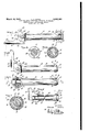
FIG. 1 in the drawing is a side elevation illustrating the lock pin in its contracted condition ready for insertion in an opening in an object to which it is to be attached.
FIG. 2 is a similar view showing the cam lever at the outer end of the pin turned to expand the holding collar at the inner end of the pin and with a cotter pin inserted to secure the operating handle and parts in such relation.
FIG. 3 is a side view of the pin in the expanded, locked condition at a right angle to the position shown in FIG. 2.
FIG. 4 is a broken longitudinal sectional view of the pin in the expanded locked condition, taken on substan tially the plane of line 44 of FIG. 3.
FIG. 5 is an enlarged cross sectional view on substantially the plane of line 5--5 of FIG. 1 showing particularly the three segments of the expansible holding collar.
FIG. 6 is a similar view on substantially the plane of line 6-6 of FIG. -l, showing in particular the contracting spring engaged about the segments of the holding collar.
FIG. 7 is a cross sectional view taken on line 7-7 of FIG. 4 showing the collar and contracting spring in the expanded condition.
As shown in the several views this lock pin is made up of a central bolt or center pin 10 having an annular enlarged head 11 at the inner end, connected with the body of the bolt by a beveled, conical wedge 12 and a surrounding sleeve :13 by which an expansible and contractible collar 14 can be expanded by forcing it up the incline of the spreader cone or be contracted by allowing it to ride down the slope of this cone.
The enlarged head of the bolt has an abrupt abutment shoulder 15 at the outer termination of the inclined conical ramp which forms the spreader wedge to provide ample support for the expanded collar.
Spring expansive and contractive effect is imparted to the collar by making it in three segments 16, 17, 18 and by surrounding these segments by a fiat sphincter spring 3,081,663 Patented Mar. 19,, 1963 19 seated in a groove 20 formed in the three segments.
This spring yields to permit expansive movement of the collar segments when the bolt and sleeve are relatively shifted to force the collar segments up the incline 12, that is from the FIG. 1 to the FIG. 4 position and serves to ride the segments down the incline of the cone when bolt and sleeve are relatively shifted in the opposite direction, that is from the FIG. 4 back to the FIG. 1 position.
The means for relatively shifting bolt and sleeve consists in the present disclosure of a cam lever 21 pivoted on the outer end of the bolt by a cross pin 22 and having a cam formation 23 applying thrust to the outer end of the actuating sleeve 13.
A thrust washer is interposed between the outer end of the sleeve and the cam projections of the lever. This thrust washer 24 is shown as having side extensions or lugs 25, making it a yoke slidably engaged over the outer end of the bolt and the cam lever 21 is shown as having parallel sides 26 disposed within the yoke of the thrust washer and having parallel cam surfaces 23 engaging the washer at opposite sides of the center pin 10.
The parallel sides 25 of the thrust washer yokeare shown as having slots 27 for free passage of the pivot pin 22 permitting free sliding movement of the washer over the center pin resulting from action of the cam lever.
The arms 25 of the washer yoke are shown as perforated at 28 and the sides 26 of the cam lever are shown as having corresponding openings 29 to register with openings 28 when the cam lever is in the collar expanded position, FIGS. 2, 3 and 4, to receive a cotter pin 30, wire or other such safety device.
The complete lock pin consists of but few strong parts and these can be secured together in proper relation by the simple act of assembly. The expansible spring holding collar may first be slipped over the center pin and then after the yoke, which serves as a thrust washer, is located over the outer end of the center pin and the cam lever is located in place it is only necessary to slip the pivot pin 22 through the thrust yoke, cam lever and center pin whereupon the parts will be secured in their proper relation as shown in FIG. 1.
In the contracted condition illustrated in FIG. 1, the lock pin may be inserted in the seat or opening in which it is to be used and it then may be secured and locked in that position by simply turning the cam lever 21 down into the position shown in FIGS. 2 and 3, where it may be locked against accidental release by insertion of the cotter pin 30 or other such element through the registering openings 28 and 29 in the thrust yoke and cam lever.
In the expanded condition illustrated in FIGS. 2, 3 and 4 the spring holding collar 14 is solidly seated on the shoulder 15 of the center pin and provides a substantially complete circumferential abutment for locking the pin in place and capable of carrying any load to which the pin may be subjected.
At the outer end the thrust washer provides a companion opposed shoulder which in cooperation with the holding shoulder of the collar at the inner end of the pin may serve to secure intermediate parts together over the sleeve portion of the pin.
If necessary or desirable washers or other filler or spacer elements may be engaged upon the sleeve in back of the thrust washer 24.
What is claimed is:
A lock pin comprising an elongated cylindrical bolt having a body and a head at one end provided with an inwardly faced annular abutment shoulder of greater diameter than the bolt diameter and a conical ramp extending from said shoulder down to the body of the bolt,
a radially expansible and contractible segmented abutment collar on said bolt of a diameter less than said annular shoulder in the contracted state and expansible by engagement over said conical ramp to greater diameter than said annular shoulder and to project radially beyond the edge of said annular shoulder,
the segments of said segmented collar having an annular groove therein,
a sphincter spring seated in said groove for contracting said collar over said conically inclined ramp down to the diameter of the body of said bolt,
a sleeve longitudinally slidable over the bolt into collar expanding engagement with said collar and movable in the opposite direction to permit contracting movement of the collar over the inclined ramp effected by contraction of the sphincter spring and means at the opposite end of the bolt for effecting sliding movernent of said collar expanding sleeve to expand said collar radially beyond the circumference of the sleeve to thereby serve as a substantially complete circumferential abutment at the end of said sleeve,
said means including a cam lever having parallel cam forming sides disposed at opposite sides of the bolt and pivoted on said bolt,
a thrust washer mounted on the bolt and disposed between said cam forming sides of the cam lever and the adjacent end of said sleeve,
said thrust washer having parallel sides projecting from opposite edge portions of the same into position at the outside of said cam forming sides of the cam lever,
said cam lever being pivoted on the bolt by a pivot pin extending through said sides of the Washer and said sides of the washer having slots for free passage of said pivot pin extending longitudinally of the bolt axis to permit movement of the thrust washer in unison with the sleeve,
said cam forming sides of the cam lever and said extended sides of the thrust washer having openings therethrough registering in the collar expanding position of the cam lever for the reception of a safety wire for securing the parts in the collar expanded condition.
References Cited in the file of this patent UNITED STATES PATENTS 1,212,871 Abbott Jan. 16, 1917 1,922,099 Kilian Aug. 15, 1933 2,377,077 Gay et al May 29, 1945 2,782,672 Davis Feb. 26, 1957 2,786,383 Bachman Mar. 26, 1957 2,865,076 Newton et a1. Dec. 23, 1958 FOREIGN PATENTS 988,724 France Apr. 30, 1951 663,755 Great Britain Dec. 27,
Priority Applications (1)
| Application Number | Priority Date | Filing Date | Title |
|---|---|---|---|
| US90058A US3081663A (en) | 1961-02-17 | 1961-02-17 | Lock pin with pivotable cam means and having substantially 360 deg. holding effect |
Applications Claiming Priority (1)
| Application Number | Priority Date | Filing Date | Title |
|---|---|---|---|
| US90058A US3081663A (en) | 1961-02-17 | 1961-02-17 | Lock pin with pivotable cam means and having substantially 360 deg. holding effect |
Publications (1)
| Publication Number | Publication Date |
|---|---|
| US3081663A true US3081663A (en) | 1963-03-19 |
Family
ID=22221094
Family Applications (1)
| Application Number | Title | Priority Date | Filing Date |
|---|---|---|---|
| US90058A Expired - Lifetime US3081663A (en) | 1961-02-17 | 1961-02-17 | Lock pin with pivotable cam means and having substantially 360 deg. holding effect |
Country Status (1)
| Country | Link |
|---|---|
| US (1) | US3081663A (en) |
Cited By (10)
| Publication number | Priority date | Publication date | Assignee | Title |
|---|---|---|---|---|
| US3152375A (en) * | 1962-12-03 | 1964-10-13 | Richard H Blakeley | Quick release fastener |
| US3793685A (en) * | 1971-03-03 | 1974-02-26 | H Knecht | Coupling apparatus for the mooring of boats or the like |
| FR2263187A1 (en) * | 1974-03-04 | 1975-10-03 | Butler Automatic Inc | |
| US4125048A (en) * | 1977-09-09 | 1978-11-14 | Hardin Russell W | Hitch pin |
| US4274649A (en) * | 1979-02-15 | 1981-06-23 | Vanderhorst Ed W | Bicycle trailer and hitch |
| US4579364A (en) * | 1984-08-06 | 1986-04-01 | Kranz Roy F | Releasable lock mechanism for hitch pins |
| US20060204349A1 (en) * | 2003-06-30 | 2006-09-14 | Master Lock Company | Integrated pin and clip |
| US7878526B1 (en) | 2008-09-26 | 2011-02-01 | Jantzen James K | Magnetic trailer hitch pin |
| US8079614B1 (en) * | 2010-06-28 | 2011-12-20 | Toyota Motor Engineering & Manufacturing North America, Inc. | Towmotor secondary lock |
| US20160114639A1 (en) * | 2014-10-24 | 2016-04-28 | Cequent Performance Products, Inc. | Receiver pin locking device |
Citations (8)
| Publication number | Priority date | Publication date | Assignee | Title |
|---|---|---|---|---|
| US1212871A (en) * | 1916-10-11 | 1917-01-16 | Leonard G Abbott | Bottle-stopper. |
| US1922099A (en) * | 1931-07-17 | 1933-08-15 | Frederick K Kilian | Caster for furniture and the like |
| US2377077A (en) * | 1943-07-24 | 1945-05-29 | Gay Bert | Expansion nut |
| FR988724A (en) * | 1949-06-17 | 1951-08-30 | Extendable cap | |
| GB663755A (en) * | 1948-06-19 | 1951-12-27 | Alfred Thomas Porter | Improvements in the attachment of tubes to other tubes or to prepared anchorages |
| US2782672A (en) * | 1954-03-11 | 1957-02-26 | Davis Aircraft Products Inc | Lock pin having eccentrically actuated plunger and cooperating locking slide means |
| US2786383A (en) * | 1953-10-12 | 1957-03-26 | D W Price Corp | Cam operated ball detent clevis pin |
| US2865076A (en) * | 1954-02-16 | 1958-12-23 | Harold E Koch | Quick release self-locking shear pin |
-
1961
- 1961-02-17 US US90058A patent/US3081663A/en not_active Expired - Lifetime
Patent Citations (8)
| Publication number | Priority date | Publication date | Assignee | Title |
|---|---|---|---|---|
| US1212871A (en) * | 1916-10-11 | 1917-01-16 | Leonard G Abbott | Bottle-stopper. |
| US1922099A (en) * | 1931-07-17 | 1933-08-15 | Frederick K Kilian | Caster for furniture and the like |
| US2377077A (en) * | 1943-07-24 | 1945-05-29 | Gay Bert | Expansion nut |
| GB663755A (en) * | 1948-06-19 | 1951-12-27 | Alfred Thomas Porter | Improvements in the attachment of tubes to other tubes or to prepared anchorages |
| FR988724A (en) * | 1949-06-17 | 1951-08-30 | Extendable cap | |
| US2786383A (en) * | 1953-10-12 | 1957-03-26 | D W Price Corp | Cam operated ball detent clevis pin |
| US2865076A (en) * | 1954-02-16 | 1958-12-23 | Harold E Koch | Quick release self-locking shear pin |
| US2782672A (en) * | 1954-03-11 | 1957-02-26 | Davis Aircraft Products Inc | Lock pin having eccentrically actuated plunger and cooperating locking slide means |
Cited By (12)
| Publication number | Priority date | Publication date | Assignee | Title |
|---|---|---|---|---|
| US3152375A (en) * | 1962-12-03 | 1964-10-13 | Richard H Blakeley | Quick release fastener |
| US3793685A (en) * | 1971-03-03 | 1974-02-26 | H Knecht | Coupling apparatus for the mooring of boats or the like |
| FR2263187A1 (en) * | 1974-03-04 | 1975-10-03 | Butler Automatic Inc | |
| US4125048A (en) * | 1977-09-09 | 1978-11-14 | Hardin Russell W | Hitch pin |
| US4274649A (en) * | 1979-02-15 | 1981-06-23 | Vanderhorst Ed W | Bicycle trailer and hitch |
| US4579364A (en) * | 1984-08-06 | 1986-04-01 | Kranz Roy F | Releasable lock mechanism for hitch pins |
| US20060204349A1 (en) * | 2003-06-30 | 2006-09-14 | Master Lock Company | Integrated pin and clip |
| US7878526B1 (en) | 2008-09-26 | 2011-02-01 | Jantzen James K | Magnetic trailer hitch pin |
| US8079614B1 (en) * | 2010-06-28 | 2011-12-20 | Toyota Motor Engineering & Manufacturing North America, Inc. | Towmotor secondary lock |
| US20160114639A1 (en) * | 2014-10-24 | 2016-04-28 | Cequent Performance Products, Inc. | Receiver pin locking device |
| US9616723B2 (en) * | 2014-10-24 | 2017-04-11 | Cequent Performance Products, Inc. | Receiver pin locking device |
| US10654327B2 (en) | 2014-10-24 | 2020-05-19 | Horizon Global Americas Inc. | Receiver pin locking device |
Similar Documents
| Publication | Publication Date | Title |
|---|---|---|
| US2886355A (en) | Coupled assemblies and coupling ring for use therein | |
| US3081663A (en) | Lock pin with pivotable cam means and having substantially 360 deg. holding effect | |
| US2401856A (en) | Retaining washer and the like | |
| US4114509A (en) | Fastener plunger entry resistance means | |
| US2367480A (en) | Nut for quick attachment | |
| US3055100A (en) | Method of forming interlocking joint between telescoped members | |
| US2839808A (en) | Fastening devices | |
| US2635901A (en) | Joint for smooth-surfaced pipe | |
| US4318630A (en) | Locking device for a shaft coupling mechanism | |
| US2340423A (en) | Expansion rivet | |
| US2975667A (en) | Retaining ring for rotary stud fastener | |
| US2731280A (en) | Resilient pipe-connector with multipart clamp | |
| US2246852A (en) | Snap fastener | |
| GB969945A (en) | Fastening devices | |
| US2292467A (en) | Means for anchoring pins into metallic members | |
| US2290776A (en) | Attaching device | |
| US2942897A (en) | Fastening device | |
| JPH06173920A (en) | Self-blocking type blind-fastener | |
| US3125790A (en) | Releasable coupling | |
| US2463253A (en) | Coupling | |
| US2246834A (en) | Locking hitch bolt | |
| US3315557A (en) | Expansion shell assembly | |
| US2528003A (en) | Umbrella lock | |
| US1607274A (en) | Means for attaching parts or members together | |
| US2030170A (en) | Rivet |