US3083381A - Mattress construction - Google Patents
Mattress construction Download PDFInfo
- Publication number
- US3083381A US3083381A US12060A US1206060A US3083381A US 3083381 A US3083381 A US 3083381A US 12060 A US12060 A US 12060A US 1206060 A US1206060 A US 1206060A US 3083381 A US3083381 A US 3083381A
- Authority
- US
- United States
- Prior art keywords
- sacks
- mattress
- spring
- springs
- series
- Prior art date
- Legal status (The legal status is an assumption and is not a legal conclusion. Google has not performed a legal analysis and makes no representation as to the accuracy of the status listed.)
- Expired - Lifetime
Links
Images


Classifications
-
- A—HUMAN NECESSITIES
- A47—FURNITURE; DOMESTIC ARTICLES OR APPLIANCES; COFFEE MILLS; SPICE MILLS; SUCTION CLEANERS IN GENERAL
- A47C—CHAIRS; SOFAS; BEDS
- A47C27/00—Spring, stuffed or fluid mattresses or cushions specially adapted for chairs, beds or sofas
- A47C27/08—Fluid mattresses or cushions
- A47C27/088—Fluid mattresses or cushions incorporating elastic bodies, e.g. foam
-
- A—HUMAN NECESSITIES
- A47—FURNITURE; DOMESTIC ARTICLES OR APPLIANCES; COFFEE MILLS; SPICE MILLS; SUCTION CLEANERS IN GENERAL
- A47C—CHAIRS; SOFAS; BEDS
- A47C27/00—Spring, stuffed or fluid mattresses or cushions specially adapted for chairs, beds or sofas
- A47C27/04—Spring, stuffed or fluid mattresses or cushions specially adapted for chairs, beds or sofas with spring inlays
- A47C27/06—Spring inlays
- A47C27/063—Spring inlays wrapped or otherwise protected
- A47C27/064—Pocketed springs
-
- A—HUMAN NECESSITIES
- A47—FURNITURE; DOMESTIC ARTICLES OR APPLIANCES; COFFEE MILLS; SPICE MILLS; SUCTION CLEANERS IN GENERAL
- A47C—CHAIRS; SOFAS; BEDS
- A47C27/00—Spring, stuffed or fluid mattresses or cushions specially adapted for chairs, beds or sofas
- A47C27/08—Fluid mattresses or cushions
- A47C27/081—Fluid mattresses or cushions of pneumatic type
Description
' April 2, 1963 L. BAILEY 3,083,381
MATTRESS CONSTRUCTION Filed March 1. 1960 3 Sheets-Sheet l INVENTOR. THEODOQE. L BA! LEY ATTOQHEY-S April 2,, 1963 T. L. BAILEY MATTRESS CONSTRUCTION 3 Sheets-Sheet 2 Filed March 1. 1960 FIG-.3
2% MM; .m/m
ATTOZNEYS April 2,, 1963 T. L. BAILEY MATTRESS CONSTRUCTION 3 Sheets-Sheet 3 Filed March 1. 1960 INVENTOR. TH Eoooras L. BAI LEY Unite Sttes Patent 3,983,381 MATTRESS CONSTRUCTION Theodore L. Bailey, Havana, Cuba (529 Country Line Road, Radnor, Pa.) Filed Mar. 1, 1960, Ser. No. 12,060 7 Claims. (Cl. -347) This invention relates generally to mattress constructions, and more particularly has reference to a generally improved mattress having a novelly designed casing and core, cooperating in such a manner as to impart to the mattress highly improved characteristics as regards resiliency, comfort, sanitation, and durability.
In carrying out the invention, I provide a complete mattress, each main component of which is specially designed for cooperating to particular advantage with the remaining components of the mattress. In said complete construction, I incorporate a novelly constructed mattress casing, an improved inner construction or core, and an eificient, strong assembly of said casing with the core.
It is further proposed, in a main embodiment of the invention, to incorporate heating means in the mattress, designed to cooperate with the above-mentioned components in such a way as to provide a generally improved mattress of the electrically-heated type.
Still further, it is proposed, in carrying out the inventive concept, to incorporate in the core a means for individually confining coil springs in sacks, which means will be especially designed to permit an elongated series of springs to be housed in sacks all of which are formed out of a single length of flexible sheet plastic. Thus, in permitting all the sacks to be integrally joined, and formed out of a single plastic sheet, I achieve durability andv sanitation through the use of plastic material, while at the same time simplifying manufacture by the provision of a single sheet for constructing the spring sacks or pockets, said sheet being swiftly foldable and being then cut and heat-sealed at selected locations, to produce the elongated row of upright, integrally joined sacks.
A further object is to adapt the sacks for use as sealed, communicating compartments into which air may be pumped, whereby the characteristic of resilient compressibility may be imparted to the sealed sacks or pockets either by inflating the same with air, by enclosing springs within the sacks, Or by a combination of air inflation and enclosed springs.
A further object of importance, in connection with the above-mentioned core construction, is to permit the elongated series of sacks'or pockets to be arranged in any desired manner, as for example, in a rectangular pattern composed of flat, closely spaced convolutions, thus to swiftly locate the sacks in selected positions relative to one another, defining row-s that can be staggered, or arranged in any other suitable and preferred manner.
A further object is to provide, in a preferred embodiment, means for stiffening the periphery of the mattress through the use of a special, peripheral construction of the core. In carrying out this object, it is proposed to provide a peripheral line of springs smaller than the springs occupying the main portion of the mattress area, with the smaller springs alternating with the larger springs in such a way as to provide high, uniform resiliency throughout the marginal portion of the mattress structure. I
Still another object is to provide a mattress core construction which will provide individual spring sacks or pockets, all formed out of a single piece of material, with said piece of material being so folded and cut as to not only have the desirable characteristics already mentioned herein, but also the characteristic of joining the spring sacks only at their mid-length portions with the sacks being otherwise free of connections to each other.
By reason of this arrangement, it is proposed to eliminate the undesirable characteristic noted in conventional mattresses, resulting from the fact that depression of any spring tends to pull downwardly the sacks immediately adjacent thereto. In the conventional arrangement, although it is generally claimed by the manufacturers that the springs operate individually, the fact remains that any tendency on the part of a spring to exert a downward pull on adjacent sacks when compressed obviously lessens the individual action of the springs, and also tends to produce excessive wear on the sacks or pockets.
Another object is to so design the folded and specially cut lengths of material that define the sacks or pockets, as to automatically define communicating air passages extending between adjacent sacks, so that air can enter or leave any sack during the use of the mattress, said communicating air passages being disposed in the connecting portions provided between adjacent sacks midway between the opposite extremities of the sacks.
Yet another object is to provide a novelly designed spring seating means within the sacks, so constituted as to provide semi-rigid cap means for the springs, having a desired characteristic of flexibility while still providing proper seats or abutments for the spring ends.
Still another object of importance is to provide a mattress casing construction wherein plastic materials or other synthetic substances can be employed to the maximum extent, with the casing having improved characteristics as regards flexibility in longitudinal and transverse directions.
A further object is to incorporate, in the mattress casing, the characteristic of being highly pervious to the passage of air therethrough, whereby to permit a high rate of heat exchange when a heating means is incorporated in the mattress.
Another important object of the present invention is.
to incorporate, in the entire mattress, non-allergic, highly sanitary odor-free materials to the maximum extent, as distinguished from conventional mattresses which usually employ woven fabrics, and other substances that are often of a nature productive of allergic reactions, difficult to keep sanitary, etc.
Other objects will appear from the following description, the claims appended thereto, and from the annexed drawing, in which like reference characters designate like parts throughout the several views, and wherein:
FIGURE 1 is a perspective view of a mattress formed in accordance with the present invention; 7
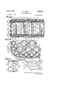
FIGURE 2 is a fragmentary top plan view in which portions have been broken away, on a scale increased above the FIGURE 1 proportions;
FIGURE 3 is a fragmentary longiutdinal sectional view on a still larger scale, taken substantially on line 3-3 of FIGURE 1;
FIGURE 4 is a horizontal section on the same scale as FIGURE 3, taken substantially on line 4-4 of FIG- FIGURE 4-A is a schematic representation of one possible arrangment of the spring series;
FIGURE 5 is a side elevational view of the sheet employed for forming the series of sacks or pockets, portions being broken away, said sheet being shown at an intermediate stage during the manufacture of the mattress core; 7
FIGURE 6 is an enlarged, partially exploded perspec tive view of one of the coil springs together with its caps or seats;
FIGURE 7 is a detail sectional view, the scale being enlarged above that of FIGURE 6, taken substantially on line 7-7 of FIGURE 6;
FIGURE 8 is a fragmentary perspective view of the series of spring pockets, the illustrated pockets or sacks 3 being shown in different stages of manufacture of the mattress;
FIGURE 9 is an enlarged longitudinal sectional view through one of the sacks or pockets, taken on line 99 of FIGURE 8;
FIGURE 10 is a longitudinal sectional view on the same scale as FIGURE 9, taken on line lit-10 of FIG- U-RE 8' through one of the sacks or pockets;
FIGURE M is a view like FIGURE 10, showing a modified end construction for the spring enclosed in the sack;
FIGURE 12 is a fragmentary perspective view of the series of spring sacks, illustrating a heating means and an inflating means associated therewith;
I FIGURE 13 is an enlarged sectional view on line 13- 13 of- FIGURE 12; and
FIGURE 14 is a still further enlarged, detail sectional view substantially on line 14-14 of FIGURE 12.
' Referring to the drawing in detail, the mattress comprising the present invention includes a casing structure generally designated 20, said casing structure being flexibly walled, and being provided with the usual generally rectangular configuration found in most mattress constructions.
Considering the particular construction of the casing structure, reference should first be had to FIGURE 3, wherein it is seen that the casing structure includes a lower face Wall 21. It will be understood, in this regard, that the mattress illustrated could be reversible, when not employed as a heated mattress.
However, in FIGURE 3 I have illustrated the mattress as having a top face wall which is designed with air, passages, to particularly facilitate the upward movement of heat through the top face wall. Thus, when the mattress is of the electrically-heated type, it would ordinarily. not be reversible, and the face wall 21 would comprise the lower wall thereof. It is obvious, however, that if a heating means is not employed in the mattress, or is not in use, though incorporated in the mattress structure, the mattress could readily be reversed.
In any event, the face wall 21 includes a lower pad 22, which in a preferred embodiment is formed of urethane. The urethane pad is comparatively thick, and as will be readily understood, is pervious to air due to its high porosity, while at the same time being light, strong, and possessed of the desired characteristics of resilient compressibility.
The urethane pad 22 has its outer surface (that is, the surface faced away from the inner construction or core) formed with intersecting transverse and longitudinal slits. The longitudinal slits have been designated. 24, while the transverse slits have been designated 26. The slits perpendicularly intersect, at uniformly spaced intervals over the entire area of the mattress, and referring to FIGURES, it will be seen thatthe slits extend approximately halfway through the thickness of the pad 22, and due to this arrangement, the pad is given a highly flexible characteristic, designed to permit the same to conform properly to the contour of the users body, while at the same time not being either excessively hard or excessively soft. The flexibility occurs both along longitudinal and transverse lines, of course, not only by reason of the nature of the urethane material itself, but also by reason of the particular slitting feature shown at 24, 26.
Overlying the outer surface of theurethane pad is a muslin backing 28,.which, of course, is inherently possessed of an open-weave characteristic rendering the same pervious to the passage of air therethrough.
J An upper face wall of the casing structure 20 has been generally designated at 29, and basically, is similar to the lower face wall 21 in construction. Thus, the upper face wall 29 includes an upper urethane pad 30, the thickness of which is approximately equal to that of the lower pad 22. The outer surface of the upper pad 30 is formed with longitudinal and transverse slits 32, 34
intersecting perpendicularly at uniformly spaced intervals corresponding to those specified with respect to the lower pad. Again, a muslin backing, designated at 35, is provided in overlying relation to the pad.
In the illustrated embodiment, the upper pad is formed with apertures 36 therethrough, over its entire area, said apertures being closely spaced and being adapted to per mit the free passage of air through the pad. The pad, of course, is already possessed of the characteristic of being highly pervious to the passage of air therethrough, but it is desirable to increase this characteristic due to the fact that the mattress is especially designed for use as an electrically-heated type of mattress structure. When an electrical heating element is incorporated in the mat tress in a manner to be described hereinafter, it is, of course, desirable that the greatest amount of the heat be caused to pass upwardly through the upper pad 30, rather than through the lower pad 22.
Referring to the lower face wall 21, this also includes a quilted or tufted covering means for the lower pad. Thus, a fabric ticking 38 cooperates with the muslinbacking 28 in enclosing a felted, flufiy, synthetic cushion or padding material, which, of, course, would be relatively soft and resiliently compressible.
Thus, the filling or padding 39, ticking 38, and backing 2t; cooperate in defining a resilient, air-pervious cushionoverlying the outer surface of the lower pad 22. Both' the ticking and the filling material, of' course, would be selected to be pervious to the passage of air, in arpreferred embodiment.
The covering or cushion means, that overlies the pad 22, is completed by transverse rows of stitching 40. The rows of stitches are uniformly spaced apart, and extend the full width of the mattress, between the oppositelongitudinal edges thereof, in line with the transverse slits 26 (see FIGURE 3).
This arrangement is selected in order to. provide a special flexibility feature in the mattress, along transverse lines. In commercial establishments, it is important to permit the mattress to be doubled upon itself for storage, sanitizing procedures, etc. By having the lines of stitching run crosswise of the mattress, this doubling or folding of the mattress is facilitated. Further, the mattress is thus designed to flex to particular advantage under the weight of the users body. The stitches, of course, draw theticking toward the backing, thus to compress the filling at the locations of the. rows of stitches, to produce the desired tufting of the lower face wall 21.
The upper face wall is similarlyformed, with. an upper ticking 42 of an air-pervious fabric overlying a felted, fluffy, synthetic padding or filling 43, said filling being confinedbetween the ticking 42 and the upper muslin backing .35. Rows of stitching 44 extend transversely of the cushion-type pad covering defined by filling 43, ticking 42, and backing 35. This stitching 44 is effective to tuft the top portion of the mattress, along paths extending transversely thereof. Therefore, the fiexure of the mattress along transverse lines, the advantages of whichhave been touched upon heretofore, is also incorporated in the top surface of the mattress.
Lower and upper peripheral rows of stitching 46, 48, respectively, join the marginal portions of the respective lower andupper backings and tickings. Outwardly from the peripheral stitching 46, 48 there are, provided peripheral reinforcing wires 50, 52, designed to stiffen and,qin effect, frame the mattress. t
The marginal portions 54, 56 of the lower and upper pads extend about the-reinforcing wires 50', 52 respectively, and the marginal parts of the lower and upper...
tickings are extended thereover to define lower andupper. welts 58, 60 respectively.
The casing structure 20 also includes -a peripheral side wall connected between the marginal portions of the upper and lower face walls. The side wall has been generally designated 62, and includes a side wall backing 64, which may be of fabric or any other suitable sheet material having the desiredcharaoteristics of strength and fiexilibility. A covering piece 66, also of flexible sheet material, cooperates with the backing piece 64 in enclosing a padding or filling 68, the material of which may be identical to the material of the fillings 39, 43.
At selected intervals throughout the periphery of the mattress, ventilators 70 are mounted in the side wall. These are conventional per se, and accordingly need not be described in detail, other than to point out that they permit the free passage of air into and out of the mattress core.
The top and bottom edges of the backing piece 64 enclose the reinforcing wires, and are secured to the adjacent edges of the tickings and of the outer or covering piece 66. This completes the construction of the mattress casing structure 20.
Referring now to the mattress core, this has been gen erally designated 72, and in the illustrated embodiment, includes an inner spring series 74 and an outer spring series 76 (see FIGURES 4 and 4-A).
Each series of springs comprises an elongated row of pockets, in each of which a compression, coil spring is disposed. Said row of pockets, by reason of a construction to be described hereinafter, is flexible in any selected direction, and thus, a continuous, elongated row of the same can be arranged in any way desired in constructing a particular mattress core.
, FIGURE 4A shows one possible arrangement. Thus, in FIGURE 4-A it will be seen that the inner spring series is arranged in a rectangular area, in a plurality of'fiat convolutions 78, the row of sacks following a tortuous path from the starting end 80 to the other terminus 82 of the inner spring series. p
Q The outer spring series 76, in the illustrated arrangement, extends in a rectangular path 84, with its ends 86, 88 disposed in closely spaced relation at one corner of themattress core. The outer spring'series thus encloses the inner series, in a typical embodiment, for reasons to be made apparent hereinafter.
- Of course, the invention lends itself to any of various other arrangements, so far as the sacks are concerned, and it is mainly important to note that the inventive concept is of such a nature as to particularly adapt the sacks for disposition in any path selected by the manufacturer.
It is now appropriate to refer to FIGURE 5, to observe the manner in which the sacks or pockets of a particular series will be formed. As previously brought out, it is desirable to utilize flexible sheet plastic or similar materials to the maximum extent, and in FIGURE 5 it may be noted that there is a continuous, elongated sheet of flexible plastic generally designated at 90. This sheet extends the full length of the spring series 74 or.76, as the case may be.
The sheet is initially of rectangular configuration, and as a first step, said sheet is folded upon itself along a fold line 96 extending longitudinally and centrally of the sheet from end-to-end thereof. This defines fold portions 92, 94 which, at this stage of manufacture, will be disposed in face-contacting relation.
The next step is the formation of upper vertical slits 98 and lowervertical slits 100 in the fold portions, said slits extending through both of the face-contacting portions. The upper slits extend downwardly from the top edge of the folded sheet, terminating in spaced relation to the inner ends of the slits 100, said slits 100 extending upwardly. from the fold line 96. At their inner ends, the slits terminate in circular apertures 101 to facilitate manufacture, by preventing excessive tearing, etc.
At this point, it may be noted that the slits 98 are longer than the slits 100, for the reason that the top portions of the sacks must have excess material so as to be foldable into overlying relation to close the sacks at their upper ends.
Surrounding each slit is a cemented area, whereby the fold portions 92, 94 are bonded together over the full lengths of the slits, at opposite sides and slightly beyond the inner ends of the slits. The cemented areas have been designated at 132, 104 and are comparatively wide in the illustrated embodiment, so as to provide a distinct separation of adjacent pockets from each other, thus facilitating disposition of the pockets in selected, relative arrangements when the mattress core is being assembled.
Between the inner ends of the slits 98, 100, there is left an unsealed area, thus defining passageways 106 extending between adjacent sacks or pockets 107 to provide free communication between the pocket interiors 108 of adjacent sacks.
At this point, it may be noted that wherever it is stated that the fold portions are cemented together or otherwise bonded, it will be understood that this connection embraces heat-sealing and any other expedient known in the art of manufacture of flexible plastic articles. In fact, in the preferred embodiment, heat-sealing would probably be employed, due to the formation of the spring-retaining means from strong, yet comparatively thin plastic sheeting.
At this point, it will also be noted that by reason of the construction so far illustrated, a single sheet, folded on itself and cut and sealed in the manner described, becomes a series of upright, cylindrical sacks alternating with connecting webs Hi9, said connecting webs being slit inwardly from the opposite ends thereof along lines parallel to the lengths of the sacks.
The connecting webs 106 thus join adjacent sacks only at locations intermediate the ends of the sacks, the sacks being otherwise free of connections to each other, where by any sack may be resiliently compressed without exerting a pull in a downward direction upon adjacent sacks.
It is also important to note that at the particular location at which the adjacent sacks are joined together, passageways 106 are provided, permitting free communication between the interiors 108 of said adjacent sacks.
At selected intervals along the length of the folded sheet, there may be provided horizontal, spaced areas 112, 114 (see FIGURE 5), extended between the inner ends of the connected areas 102, 104 respectively, to provide empty sacks or pockets 110, each of which has an elongated, transverse passageway 115 therethrough to permit'comtnunication between the filled sacks 107 disposed at opposite sides of the empty sacks. The empty sacks are, in a preferred embodiment, provided at the end of each row (see FIGURE 4), to permit reversal of the direction of the spring series while still providing an air passage between the sacks located at the ends of the adjacent, connected rows.
In a typical embodiment of the invention, compression, coil springs 116 would be employed, each spring being disposed in a pocket or sack 107. I prefer to employ springs which are of reduced diameter intermediate their ends, as compared to the diameters of the ends of the springs. This is shown in FIGURE 3, to particular advantage.
Referring to FIGURE 6, each spring 116 has its lower end engaged in a lower, circular spring seat 118 having a peripheral lip 120 embracing the lowermost convolution of the spring. The upper end of the spring is seated in a cap 122, which preferably is of a semi-rigid, molded plastic material having a depending, peripheral lip 124 receiving the uppermost convolution of the spring. Diametrically extending strengthening ribs 126 are molded upon the top surface of the cap 122, and in a preferred embodiment, said cap 122 is freely perforated over its entire area as at 127. This allows a high degree of heat exchange through the cap, so that any heat accumulating within the spring sack, in an electrically-heated mattress, will be readily conducted through the sealed upper end of the sack.
So-called hog rings are employed to positively connect the caps to the upper ends of the springs, these being designated at 128 and being uniformly, angularly spaced about the circumference of the cap. These are in embracing relation to the cap periphery and the uppermost convolution of the spring, as shown in FIGURE 7, to hold the same assembled with one another.
After the springs have been assembled with their upper and lower caps or seats, they are individually depositedin their sacks 107. The sacks, of course, are already permenently closed at their lower ends, due to the formation thereof from a folded sheet of material. The upper ends of the sacks are then folded and sealed, thus to hermetically seal the individual sacks. As will be noted, the top edge portions 130, 132 of the respective fold portions 92, 94 are folded inwardly over cap 122 (see FIGURE In the illustrated arrangement, the edge portion 130'- is folded on itself, and then the edge portion 132 is disposed in overlying relation thereto, after which heat sealing 134 is employed to connect said edge portions together, thus providing an upper end wall 136 on each sack.
The construction illustrated and described above applies not only to the inner spring series, but also, to the outer spring series 76. The outer spring series, however, has smaller springs 138 than the inner spring series. Further, the sacks 140 of the outer spring series would obviously be of smaller diameter than the sacks 107 (see FIGURE 4). Also, it may be desirable to provide wider connecting webs between adjacent or juxtaposed sacks of the outer spring series. This may be desirable in order to have the smaller springs alternate with adjacent larger springs, peripherally of the mattress, in some embodiments of the invention.
Apart from the above, however, the construction of the outer spring series is identical in all respects to that of the inner spring series, in a typical embodiment of the invention.
Referring to FIGURE 11, there is here shown a modified spring construction, which may eliminate the need for a spring cap. In this arrangement, the spring 116a is provided with a horizontal top convolution or loop 142, the extremity 143 of which is bent inwardly so as to insure that the spring will not puncture the material of the sack. The purpose of the smaller springs is to provide for a more uniform and slightly increased resiliency, throughout the periphery of the mattress. The smaller springs, as will be noted, fill the caps that might ordinarily be provided if the side wall 62 were disposed directly against larger spring sacks, and this strengthens the marginal portion of the mattress. A stiffening of the edge portion of the mattress, accompanied by a proper retention of resiliency, results.
The construction so far illustrated and described can constitute a complete mattress, of the unheated type, reversible face-for-face, if desired. However, the invention lends itself to incorporation of a heating element, in a manner shown in FIGURES 12-14, should an electrically-heated mattress be desired. If a heating element is employed in accordance with the invention, it can be incorporated directly in a mattress formed as already discussed herein, so that the manufacturing operations can be simplified, due to the fact that the basic mattress is the same, whether it be heated or left unheated.
Thus, in FIGURE 12 it will be seen that I provide .a heating means generally designated 144, comprising an elongated, continuous, flat band of flexible plastic, in which there is an array of resistance wires 148. A female plug or receptacle 150 may be provided at one end of the band, and this can be mounted in the side wall, so as to receive a convenience cord, not shown, which would then be plugged into a source of electricity. Of course, it is obvious that a thermostatic means can be associated with the invention, this being well-known in the art of electric blankets, and the like, so as not to require :any illustration herein. The thermostat would control the energizing and deenergizing of the heating element, so as to cause the same to be energized only when the temperature drops to a predetermined degree, the heating element thereafter remaining in an energized condition until the thermostat operates to open the circuit.
In any event, the band 146 can be arranged in any way desired. The band could actually extend directly through the sacks, passing diametrically across each sack and extending through the passageways 106.- In this event, heat resulting from energization of the band would be transferred through the walls of the sacks.
Alternatively, the band could be threaded between the sacks, exteriorly thereof, in any of various ways. In the: illustrated arrangement, which is merely typical, but which is obviously not the only one that need be used,.I showthe band as being threaded zigzag fashion along a row of sacks 107. The band passes about one side of alternate sacks, and about the other sides of sacks intervening'between said alternate sacks. Further, the band passes under one connecting web, and then over the next, asshown in FIGURE 12.
In this way, the heating element is caused to extend in convolutions following those of the inner spring series, said heating element extending along an undulating'path in each convolution. Uniform distribution of the heat is. accordingly produced, over the entire area of the mattress.
It will be understood that in mattresses for double beds, it may be desirable to incorporate separate heating elements, with dual controls, so that each side of the mattresscan be heated to a selected temperature, independently of the'other side, to suit the individual users of the mattress.
Of course, the heat is permitted to rise within the mattress, passingupwardly through the urethane pad, which as indicated above, is highly pervious to the passage of air. It is also a characteristicof the invention that in some forms, I will provide means for inflating the several sacks 107 or 140. To this end, there is provided an air. inlet tube 152, the inlet end of which isprovided with a check valve 154, as for example, a conventional automobile tire valve. The check valve is mounted in the side wall of the mattress, in the same manner as the receptacle 150 would be mounted. A conventional hand pump, not shown, can be applied for the purpose of pumping air into the mattress. The air so-pumped will becaused to enter the sacks 107 or 140, and said air will, of course, be'distributed through the entire length of the spring series due to the communicating passages 106 between adjacent sacks. The several sack interiors, being in free communication with one another, define an air chamber, into which air may be pumped for the purpose of inflating thesacks.
In a mattress in which air is used in the manner specified above, it may be possible to eliminate the springs, since the air constitutes a means for imparting a resilient com.- pressibility to the sacks in the direction of their lengths, just as the springs constitute a means of this type. 'In other cases, the mattress may have both the inflatable feature and the springs. In still other cases, the mattress may simply have the springs.
Further, the air-inflation feature, though shown'in FIG- URE 12 in association with a spring series having a heat ing element, can be employed. in an unheated mattress. Conversely, the heating element may be in a mattress that is devoid of the-air-inflation feature.
In a mattress which has the air tube arrangement, both ends of the spring series would preferably have tubes such as shown at 152, equipped with valves 154' mounted in the side wall 62 of the mattress casing. In these circumstances, either valve could be connected to the pump.
The reason for having tubes at both ends of the spring series is not only to permit selection of a particular valve for use in pumping air into the series of sacks, but also, to permit both valves to be de-activated, that is, opened and maintained in an open position. This-would be for the purpose of eliminating the sack inflation feature as a means for imparting the characteristic of resilient compressibility to the sacks, so that the springs would, in this event, assume the full function of imparting said compressibility to the sacks. Should, at a later date, it be desired to supplement the spring action, then it would be possible to allow the valves to revert to their normal, closed positions, after which air would be pumped into the series of sacks as desired.
It is believed apparent that the invention is not necessarily confined to the specific use or uses thereof described above, since it may be utilized for any purpose to which it may be suited. Nor is the invention to be necessarily limited to the specific construction illustrated and described, since such construction is only intended to be illustrative of the principles of operation and the means presently devised to carry out said principles, it being considered that the invention comprehends any changes in construction that may be permitted within the scope of the appended claims.
What is claimed is:
1. A mattress comprising a plurality of upstanding closely spaced vertically elongated substantially cylindrical sacks having a side wall and opposed closed ends, each of said sacks being for-med of an impervious flexible material, resilient means disposed within each of said sacks constantly biasing said opposed ends for movement away from each other, means connecting each adjacent pair of sacks intermediate said opposed ends for the passage of a fluid therethrough, means connecting one of said sacks with the source of fluid under pressure, a peripheral covering piece formed of a flexible material, an upper pad formed of a flexible flame-proof material and extending across the upper ends of said sacks, a lower pad formed of a flexible flame-proof material and extending across the lower ends of said sacks, and means connecting said upper and lower pads with adjacent ends of said peripheral covering piece.
2. A mattress as defined in claim 1, and heating means surrounding each of said sacks.
3. A mattress as defined in claim 1 and electrical heating means threaded between each adjacent pair of sacks.
4. A mattress as defined in claim 1 and means for venting said peripheral covering piece to the atmosphere.
5. A mattress as defined in claim 4 and means in said upper pad venting said mattress to the atmosphere.
6. A mattress as defined in claim 1, wherein said resilient means comprises a helicoidal spring for each of said sacks, each of said springs having convolutions of reduced diameter intermediate their respective ends, and a substantially circular spring seat interposed between the uppermost and lowermost convolutions of each of said springs and the adjacent one of said opposed ends of said sacks.
7. A mattress comprising a plurality of upstanding closely spaced vertically elongated substantially cylindrical sacks having a side wall and opposed closed ends, each of said sacks having a helicoidal spring disposed therein constantly biasing said opposed ends for movement away from each other, said springs having convolutions of reduced diameter intermediate their opposed ends, means connecting each adjacent pair of sacks intermediate said opposed ends for the passage of the fluid therethrough, means connecting one of said sacks with the source of fluid under pressure, a spring seat for each end convolution of said spring, said spring seats being interposed between the upper and lower closed ends and the adjacent convolutions of said spring, a peripheral covering piece formed of a flexible material, an upper pad formed of a flexible flame-proof material and extending across the upper ends of said sacks, a lower pad formed of a flexible flame-proof material and extending across the lower ends of said sacks, said upper and lower pads having longitudinally and transversely extending slits formed therein extending inwardly from the respective outer sides thereof, and means connecting said upper and lower pads with adjacent ends of said peripheral covering piece.
References Cited in the file of this patent UNITED STATES PATENTS 1,284,384 Lewis Nov. 12, 1918 1,989,582 Becker Jan. 29, 1935 2,260,596 Young Oct. 28, 1941 2,272,493 Williams Feb. 10, 1942 2,434,641 Burns Jan. 20, 1948 2,790,979 Gleason May 7, 1957 2,805,429 Woller Sept. 10, 1957 2,862,214 Thompson et a1. Dec. 2, 1958 2,882,959 Burkart Apr. 21, 1959 FOREIGN PATENTS 397,707 Great Britain Aug. 31, 1933
Claims (1)
1. A MATTRESS COMPRISING A PLURALITY OF UPSTANDING CLOSELY SPACED VERTICALLY ELONGATED SUBSTANTIALLY CYLINDRICAL SACKS HAVING A SIDE WALL AND OPPOSED CLOSED ENDS, EACH OF SAID SACKS BEING FORMED OF AN IMPERVIOUS FLEXIBLE MATERIAL, RESILIENT MEANS DISPOSED WITHIN EACH OF SAID SACKS CONSTANTLY BIASING SAID OPPOSED ENDS FOR MOVEMENT AWAY FROM EACH OTHER, MEANS CONNECTING EACH ADJACENT PAIR OF SACKS INTERMEDIATE SAID OPPOSED ENDS FOR THE PASSAGE OF A FLUID THERETHROUGH, MEANS CONNECTING ONE OF SAID SACKS WITH THE SOURCE OF FLUID UNDER PRESSURE, A PERIPHERAL COVERING PIECE FORMED OF A FLEXIBLE MATERIAL, AN UPPER PAD FORMED OF A FLEXIBLE FLAME-PROOF MATERIAL AND EXTENDING ACROSS THE UPPER ENDS OF SAID SACKS, A LOWER PAD FORMED OF A FLEXIBLE FLAME-PROOF MATERIAL AND EXTENDING ACROSS THE LOWER ENDS OF SAID SACKS, AND MEANS CONNECTING SAID UPPER AND LOWER PADS WITH ADJACENT ENDS OF SAID PERIPHERAL COVERING PIECE.
Priority Applications (1)
| Application Number | Priority Date | Filing Date | Title |
|---|---|---|---|
| US12060A US3083381A (en) | 1960-03-01 | 1960-03-01 | Mattress construction |
Applications Claiming Priority (1)
| Application Number | Priority Date | Filing Date | Title |
|---|---|---|---|
| US12060A US3083381A (en) | 1960-03-01 | 1960-03-01 | Mattress construction |
Publications (1)
| Publication Number | Publication Date |
|---|---|
| US3083381A true US3083381A (en) | 1963-04-02 |
Family
ID=21753183
Family Applications (1)
| Application Number | Title | Priority Date | Filing Date |
|---|---|---|---|
| US12060A Expired - Lifetime US3083381A (en) | 1960-03-01 | 1960-03-01 | Mattress construction |
Country Status (1)
| Country | Link |
|---|---|
| US (1) | US3083381A (en) |
Cited By (30)
| Publication number | Priority date | Publication date | Assignee | Title |
|---|---|---|---|---|
| US3246118A (en) * | 1964-01-31 | 1966-04-12 | Forrest M Sayles | Radiant heating furniture |
| US3265438A (en) * | 1964-11-27 | 1966-08-09 | Regan | Seat |
| US3772717A (en) * | 1971-02-05 | 1973-11-20 | Y Yuen | Inflatable mattresses and cushions |
| US5020852A (en) * | 1990-05-29 | 1991-06-04 | Marion Laura E | Bicycle seat |
| EP0853901A2 (en) * | 1997-01-07 | 1998-07-22 | SCHLARAFFIA-WERKE HUSER GMBH. & CO. KG. | Mattress |
| WO2000045676A1 (en) * | 1999-02-05 | 2000-08-10 | L & P Property Management Company | Pocketed bedding or seating product |
| US6173464B1 (en) * | 1999-05-07 | 2001-01-16 | L&P Property Management Company | Pocketed bedding or seating product |
| WO2002039853A1 (en) * | 2000-11-02 | 2002-05-23 | L & P Property Management Company | Pocketed bedding or seating product with cushioning pads inside pockets |
| US6447865B1 (en) | 1998-07-22 | 2002-09-10 | Gaymar Industries, Inc. | Gelatinous composite article and construction |
| US6606754B1 (en) | 1999-03-30 | 2003-08-19 | Gaymar Industries, Inc. | Supported hypo/hyperthermia pad |
| US20120198616A1 (en) * | 2010-09-13 | 2012-08-09 | Tarek Makansi | Distributed thermoelectric string and insulating panel and applications for local heating, local cooling, and power generation from heat |
| WO2012155131A1 (en) * | 2011-05-12 | 2012-11-15 | Sealy Technology, Llc | Advanced conformance encased coil spring units |
| WO2016100074A1 (en) * | 2014-12-16 | 2016-06-23 | L&P Property Mangment Company | Pocketed spring assembly comprising perimeter string of springs having rectangular convolutions |
| US20160367042A1 (en) * | 2015-06-22 | 2016-12-22 | Herman Franklin Fisher | Pocketed foam systems and methods |
| US9596944B2 (en) | 2011-07-06 | 2017-03-21 | Tempronics, Inc. | Integration of distributed thermoelectric heating and cooling |
| US9638442B2 (en) | 2012-08-07 | 2017-05-02 | Tempronics, Inc. | Medical, topper, pet wireless, and automated manufacturing of distributed thermoelectric heating and cooling |
| US9676310B2 (en) | 2012-09-25 | 2017-06-13 | Faurecia Automotive Seating, Llc | Vehicle seat with thermal device |
| US20170354267A1 (en) * | 2016-06-08 | 2017-12-14 | Bedgear Llc | Independent suspension spring assembly |
| US20180078046A1 (en) * | 2015-04-03 | 2018-03-22 | Mammoth Sport Limited | Pressure control layer for a mattress or seating |
| US9989282B2 (en) | 2010-09-13 | 2018-06-05 | Tempronics, Inc. | Distributed thermoelectric string and insulating panel |
| US10165867B2 (en) | 2016-05-27 | 2019-01-01 | L&P Property Management Company | Pocketed spring assembly comprising perimeter strings of springs having rectangular convolutions |
| US10228165B2 (en) | 2013-11-04 | 2019-03-12 | Tempronics, Inc. | Thermoelectric string, panel, and covers for function and durability |
| US10598242B2 (en) | 2016-05-20 | 2020-03-24 | Sealy Technology, Llc | Coil springs with non-linear loading responses and mattresses including the same |
| US10617223B2 (en) | 2018-06-06 | 2020-04-14 | Steven Bayer | Independent spring support structure |
| US11013340B2 (en) * | 2018-05-23 | 2021-05-25 | L&P Property Management Company | Pocketed spring assembly having dimensionally stabilizing substrate |
| US11033114B2 (en) | 2015-12-17 | 2021-06-15 | Sealy Technology, Llc | Coil-in-coil spring with variable loading response and mattresses including the same |
| US11051631B2 (en) | 2016-01-21 | 2021-07-06 | Sealy Technology, Llc | Coil-in-coil springs with non-linear loading responses and mattresses including the same |
| US11076705B2 (en) | 2014-05-30 | 2021-08-03 | Sealy Technology, Llc | Spring core with integrated cushioning layer |
| US11246426B2 (en) * | 2018-03-06 | 2022-02-15 | Bedgear, Llc | Mattress assembly and method |
| US20220071405A1 (en) * | 2016-10-27 | 2022-03-10 | Bedgear, Llc | Mattress assembly and method |
Citations (10)
| Publication number | Priority date | Publication date | Assignee | Title |
|---|---|---|---|---|
| US1284384A (en) * | 1918-05-15 | 1918-11-12 | William Lewis | Spring-mattress. |
| GB397707A (en) * | 1932-10-31 | 1933-08-31 | John Maurice Davis | Improvements in and connected with spring fillers for mattresses, cushions and the like |
| US1989582A (en) * | 1933-06-07 | 1935-01-29 | William C Becker | Electrically heated mattress, pad, cushion, and the like |
| US2260596A (en) * | 1940-05-16 | 1941-10-28 | L A Young Spring & Wire Corp | Spring assembly and upholstery supporting mat therefor |
| US2272493A (en) * | 1938-04-29 | 1942-02-10 | Harold E Williams | Cushion structure |
| US2434641A (en) * | 1946-02-20 | 1948-01-20 | Henry L Burns | Resilient seat cushion |
| US2790979A (en) * | 1954-11-08 | 1957-05-07 | Nachman Corp | Spring assembly for upholstery |
| US2805429A (en) * | 1954-10-21 | 1957-09-10 | Simmons Co | Mattress manufacture |
| US2862214A (en) * | 1956-10-04 | 1958-12-02 | Marspring Corp | Cushion or mattress construction and method of manufacture |
| US2882959A (en) * | 1956-07-09 | 1959-04-21 | Burkart Mfg Company F | Embedded spring cushion construction |
-
1960
- 1960-03-01 US US12060A patent/US3083381A/en not_active Expired - Lifetime
Patent Citations (10)
| Publication number | Priority date | Publication date | Assignee | Title |
|---|---|---|---|---|
| US1284384A (en) * | 1918-05-15 | 1918-11-12 | William Lewis | Spring-mattress. |
| GB397707A (en) * | 1932-10-31 | 1933-08-31 | John Maurice Davis | Improvements in and connected with spring fillers for mattresses, cushions and the like |
| US1989582A (en) * | 1933-06-07 | 1935-01-29 | William C Becker | Electrically heated mattress, pad, cushion, and the like |
| US2272493A (en) * | 1938-04-29 | 1942-02-10 | Harold E Williams | Cushion structure |
| US2260596A (en) * | 1940-05-16 | 1941-10-28 | L A Young Spring & Wire Corp | Spring assembly and upholstery supporting mat therefor |
| US2434641A (en) * | 1946-02-20 | 1948-01-20 | Henry L Burns | Resilient seat cushion |
| US2805429A (en) * | 1954-10-21 | 1957-09-10 | Simmons Co | Mattress manufacture |
| US2790979A (en) * | 1954-11-08 | 1957-05-07 | Nachman Corp | Spring assembly for upholstery |
| US2882959A (en) * | 1956-07-09 | 1959-04-21 | Burkart Mfg Company F | Embedded spring cushion construction |
| US2862214A (en) * | 1956-10-04 | 1958-12-02 | Marspring Corp | Cushion or mattress construction and method of manufacture |
Cited By (59)
| Publication number | Priority date | Publication date | Assignee | Title |
|---|---|---|---|---|
| US3246118A (en) * | 1964-01-31 | 1966-04-12 | Forrest M Sayles | Radiant heating furniture |
| US3265438A (en) * | 1964-11-27 | 1966-08-09 | Regan | Seat |
| US3772717A (en) * | 1971-02-05 | 1973-11-20 | Y Yuen | Inflatable mattresses and cushions |
| US5020852A (en) * | 1990-05-29 | 1991-06-04 | Marion Laura E | Bicycle seat |
| EP0853901A2 (en) * | 1997-01-07 | 1998-07-22 | SCHLARAFFIA-WERKE HUSER GMBH. & CO. KG. | Mattress |
| EP0853901A3 (en) * | 1997-01-07 | 2001-01-03 | SCHLARAFFIA-WERKE HUSER GMBH. & CO. KG. | Mattress |
| US20020151243A1 (en) * | 1998-07-22 | 2002-10-17 | Flick Roland E. | Gelatinous composite article and construction |
| US6843873B2 (en) | 1998-07-22 | 2005-01-18 | Gaymar Industries, Inc. | Method of making a gelatinous composite |
| US6767621B2 (en) | 1998-07-22 | 2004-07-27 | Gaymar Industries, Inc. | Gelatinous composite article and construction |
| US20020187332A1 (en) * | 1998-07-22 | 2002-12-12 | Flick Roland E. | Gelatinous composite article and construction |
| US6447865B1 (en) | 1998-07-22 | 2002-09-10 | Gaymar Industries, Inc. | Gelatinous composite article and construction |
| US6272706B1 (en) | 1999-02-05 | 2001-08-14 | L&P Property Management Company | Bedding or seating product having bands of springs |
| WO2000045676A1 (en) * | 1999-02-05 | 2000-08-10 | L & P Property Management Company | Pocketed bedding or seating product |
| US6606754B1 (en) | 1999-03-30 | 2003-08-19 | Gaymar Industries, Inc. | Supported hypo/hyperthermia pad |
| US6871365B2 (en) | 1999-03-30 | 2005-03-29 | Gaymar Industries, Inc. | Supported hypo/hyperthermia pad |
| US6173464B1 (en) * | 1999-05-07 | 2001-01-16 | L&P Property Management Company | Pocketed bedding or seating product |
| US6490744B1 (en) * | 2000-11-02 | 2002-12-10 | L&P Property Management Company | Pocketed bedding or seating product with cushioning pads inside pockets |
| WO2002039853A1 (en) * | 2000-11-02 | 2002-05-23 | L & P Property Management Company | Pocketed bedding or seating product with cushioning pads inside pockets |
| US20120198616A1 (en) * | 2010-09-13 | 2012-08-09 | Tarek Makansi | Distributed thermoelectric string and insulating panel and applications for local heating, local cooling, and power generation from heat |
| US9989282B2 (en) | 2010-09-13 | 2018-06-05 | Tempronics, Inc. | Distributed thermoelectric string and insulating panel |
| US20150001770A1 (en) * | 2011-05-12 | 2015-01-01 | Sealy Technology, Llc | Advanced conformance encased coil spring units |
| WO2012155131A1 (en) * | 2011-05-12 | 2012-11-15 | Sealy Technology, Llc | Advanced conformance encased coil spring units |
| US9392876B2 (en) * | 2011-05-12 | 2016-07-19 | Sealy Technology, Llc | Advanced conformance encased coil spring units |
| US10571162B2 (en) | 2011-07-06 | 2020-02-25 | Tempronics, Inc. | Integration of distributed thermoelectric heating and cooling |
| US9596944B2 (en) | 2011-07-06 | 2017-03-21 | Tempronics, Inc. | Integration of distributed thermoelectric heating and cooling |
| US9638442B2 (en) | 2012-08-07 | 2017-05-02 | Tempronics, Inc. | Medical, topper, pet wireless, and automated manufacturing of distributed thermoelectric heating and cooling |
| US9676310B2 (en) | 2012-09-25 | 2017-06-13 | Faurecia Automotive Seating, Llc | Vehicle seat with thermal device |
| US10830507B2 (en) | 2013-11-04 | 2020-11-10 | Tempronics, Inc. | Thermoelectric string, panel, and covers for function and durability |
| US10228165B2 (en) | 2013-11-04 | 2019-03-12 | Tempronics, Inc. | Thermoelectric string, panel, and covers for function and durability |
| US11076705B2 (en) | 2014-05-30 | 2021-08-03 | Sealy Technology, Llc | Spring core with integrated cushioning layer |
| US9380883B1 (en) | 2014-12-16 | 2016-07-05 | L&P Property Management Company | Pocketed spring assembly comprising perimeter string of springs having rectangular convolutions |
| WO2016100074A1 (en) * | 2014-12-16 | 2016-06-23 | L&P Property Mangment Company | Pocketed spring assembly comprising perimeter string of springs having rectangular convolutions |
| US20180078046A1 (en) * | 2015-04-03 | 2018-03-22 | Mammoth Sport Limited | Pressure control layer for a mattress or seating |
| US11019936B2 (en) * | 2015-06-22 | 2021-06-01 | Zeplus, Llc | Pocketed foam systems and methods |
| US10357116B2 (en) * | 2015-06-22 | 2019-07-23 | Zeplus, Llc | Pocketed foam systems and methods |
| US20190290015A1 (en) * | 2015-06-22 | 2019-09-26 | Zeplus, Llc | Pocketed foam systems and methods |
| US20160367042A1 (en) * | 2015-06-22 | 2016-12-22 | Herman Franklin Fisher | Pocketed foam systems and methods |
| US11033114B2 (en) | 2015-12-17 | 2021-06-15 | Sealy Technology, Llc | Coil-in-coil spring with variable loading response and mattresses including the same |
| US11051631B2 (en) | 2016-01-21 | 2021-07-06 | Sealy Technology, Llc | Coil-in-coil springs with non-linear loading responses and mattresses including the same |
| US10935098B2 (en) | 2016-05-20 | 2021-03-02 | Sealy Technology, Llc | Coil springs with non-linear loading responses and mattresses including the same |
| US10598242B2 (en) | 2016-05-20 | 2020-03-24 | Sealy Technology, Llc | Coil springs with non-linear loading responses and mattresses including the same |
| US10165867B2 (en) | 2016-05-27 | 2019-01-01 | L&P Property Management Company | Pocketed spring assembly comprising perimeter strings of springs having rectangular convolutions |
| RU2754528C2 (en) * | 2016-06-08 | 2021-09-03 | Бедгир, Ллк | Spring block with independent spring-loading |
| US11503919B2 (en) * | 2016-06-08 | 2022-11-22 | Bedgear, Llc | Independent suspension spring assembly |
| CN109561765A (en) * | 2016-06-08 | 2019-04-02 | 百德基尔有限责任公司 | Independent suspension spring assembly |
| WO2017218241A1 (en) * | 2016-06-08 | 2017-12-21 | Bedgear, Llc | Independent suspension spring assembly |
| US20170354267A1 (en) * | 2016-06-08 | 2017-12-14 | Bedgear Llc | Independent suspension spring assembly |
| CN114668261A (en) * | 2016-06-08 | 2022-06-28 | 百德基尔有限责任公司 | Independent suspension spring assembly |
| US20220071405A1 (en) * | 2016-10-27 | 2022-03-10 | Bedgear, Llc | Mattress assembly and method |
| US11259644B2 (en) * | 2018-03-06 | 2022-03-01 | Bedgear, Llc | Mattress assembly and method |
| US11246426B2 (en) * | 2018-03-06 | 2022-02-15 | Bedgear, Llc | Mattress assembly and method |
| US20220117404A1 (en) * | 2018-03-06 | 2022-04-21 | Bedgear, Llc | Mattress assembly and method |
| US20210244193A1 (en) * | 2018-05-23 | 2021-08-12 | L&P Property Management Company | Method Of Making Pocketed Spring Assembly With Substrate |
| US20210235882A1 (en) * | 2018-05-23 | 2021-08-05 | L&P Property Management Company | Pocketed Spring Assembly Having Dimensionally Stabilizing Substrate |
| US11013340B2 (en) * | 2018-05-23 | 2021-05-25 | L&P Property Management Company | Pocketed spring assembly having dimensionally stabilizing substrate |
| US11771235B2 (en) * | 2018-05-23 | 2023-10-03 | L&P Property Management Company | Pocketed spring assembly having dimensionally stabilizing substrate |
| US11812860B2 (en) * | 2018-05-23 | 2023-11-14 | L&P Property Management Company | Method of making pocketed spring assembly with substrate |
| US11197557B2 (en) | 2018-06-06 | 2021-12-14 | Steven Bayer | Systems and methods of sensing independent spring support |
| US10617223B2 (en) | 2018-06-06 | 2020-04-14 | Steven Bayer | Independent spring support structure |
Similar Documents
| Publication | Publication Date | Title |
|---|---|---|
| US3083381A (en) | Mattress construction | |
| US10368655B2 (en) | Mattress | |
| US9949571B2 (en) | Spring unit for a mattress | |
| US8266745B2 (en) | Slow acting pocketed spring core having fill material inside pockets | |
| US9661932B2 (en) | Mattress | |
| US4435864A (en) | Air bed arrangement | |
| US6574814B2 (en) | Bedding or seating product having filled tube topper | |
| CN107427134B (en) | Mattress | |
| US4424600A (en) | Adjustable firmness mattress pillow top | |
| US5636397A (en) | Futon mattress | |
| WO2015017048A1 (en) | Mattress topper comprising pocketed spring assembly with at least one cushioning layer | |
| US1741847A (en) | Cushion construction | |
| CN112105276A (en) | Low density pocket spring mattress with integrated cushioning | |
| US1359801A (en) | Combination mattress and pillow | |
| US20200237109A1 (en) | Mattress | |
| WO2000019866A1 (en) | Pillow top mattress assemblies | |
| US2184808A (en) | Bed or seat cover or cushion | |
| US1846312A (en) | Pillow | |
| US2129353A (en) | Seat pad and cushion | |
| US3051966A (en) | Cushioned seat ventilator | |
| US1873212A (en) | Cushion | |
| US2291155A (en) | Article of bedding | |
| US1747374A (en) | Spring construction | |
| US3004266A (en) | Mattress construction and spring | |
| US1973651A (en) | Mattress and cushion construction |