US3338238A - Pressure gas storage container and safety breathing apparatus - Google Patents
Pressure gas storage container and safety breathing apparatus Download PDFInfo
- Publication number
- US3338238A US3338238A US330704A US33070463A US3338238A US 3338238 A US3338238 A US 3338238A US 330704 A US330704 A US 330704A US 33070463 A US33070463 A US 33070463A US 3338238 A US3338238 A US 3338238A
- Authority
- US
- United States
- Prior art keywords
- housing
- compartments
- container
- pressure gas
- center
- Prior art date
- Legal status (The legal status is an assumption and is not a legal conclusion. Google has not performed a legal analysis and makes no representation as to the accuracy of the status listed.)
- Expired - Lifetime
Links
Images
Classifications
-
- A—HUMAN NECESSITIES
- A62—LIFE-SAVING; FIRE-FIGHTING
- A62B—DEVICES, APPARATUS OR METHODS FOR LIFE-SAVING
- A62B7/00—Respiratory apparatus
- A62B7/02—Respiratory apparatus with compressed oxygen or air
-
- A—HUMAN NECESSITIES
- A62—LIFE-SAVING; FIRE-FIGHTING
- A62B—DEVICES, APPARATUS OR METHODS FOR LIFE-SAVING
- A62B9/00—Component parts for respiratory or breathing apparatus
-
- B—PERFORMING OPERATIONS; TRANSPORTING
- B63—SHIPS OR OTHER WATERBORNE VESSELS; RELATED EQUIPMENT
- B63C—LAUNCHING, HAULING-OUT, OR DRY-DOCKING OF VESSELS; LIFE-SAVING IN WATER; EQUIPMENT FOR DWELLING OR WORKING UNDER WATER; MEANS FOR SALVAGING OR SEARCHING FOR UNDERWATER OBJECTS
- B63C11/00—Equipment for dwelling or working underwater; Means for searching for underwater objects
- B63C11/02—Divers' equipment
- B63C11/18—Air supply
- B63C11/22—Air supply carried by diver
-
- F—MECHANICAL ENGINEERING; LIGHTING; HEATING; WEAPONS; BLASTING
- F17—STORING OR DISTRIBUTING GASES OR LIQUIDS
- F17C—VESSELS FOR CONTAINING OR STORING COMPRESSED, LIQUEFIED OR SOLIDIFIED GASES; FIXED-CAPACITY GAS-HOLDERS; FILLING VESSELS WITH, OR DISCHARGING FROM VESSELS, COMPRESSED, LIQUEFIED, OR SOLIDIFIED GASES
- F17C1/00—Pressure vessels, e.g. gas cylinder, gas tank, replaceable cartridge
- F17C1/14—Pressure vessels, e.g. gas cylinder, gas tank, replaceable cartridge constructed of aluminium; constructed of non-magnetic steel
-
- F—MECHANICAL ENGINEERING; LIGHTING; HEATING; WEAPONS; BLASTING
- F17—STORING OR DISTRIBUTING GASES OR LIQUIDS
- F17C—VESSELS FOR CONTAINING OR STORING COMPRESSED, LIQUEFIED OR SOLIDIFIED GASES; FIXED-CAPACITY GAS-HOLDERS; FILLING VESSELS WITH, OR DISCHARGING FROM VESSELS, COMPRESSED, LIQUEFIED, OR SOLIDIFIED GASES
- F17C1/00—Pressure vessels, e.g. gas cylinder, gas tank, replaceable cartridge
- F17C1/16—Pressure vessels, e.g. gas cylinder, gas tank, replaceable cartridge constructed of plastics materials
-
- F—MECHANICAL ENGINEERING; LIGHTING; HEATING; WEAPONS; BLASTING
- F17—STORING OR DISTRIBUTING GASES OR LIQUIDS
- F17C—VESSELS FOR CONTAINING OR STORING COMPRESSED, LIQUEFIED OR SOLIDIFIED GASES; FIXED-CAPACITY GAS-HOLDERS; FILLING VESSELS WITH, OR DISCHARGING FROM VESSELS, COMPRESSED, LIQUEFIED, OR SOLIDIFIED GASES
- F17C2201/00—Vessel construction, in particular geometry, arrangement or size
- F17C2201/01—Shape
- F17C2201/0104—Shape cylindrical
- F17C2201/0109—Shape cylindrical with exteriorly curved end-piece
-
- F—MECHANICAL ENGINEERING; LIGHTING; HEATING; WEAPONS; BLASTING
- F17—STORING OR DISTRIBUTING GASES OR LIQUIDS
- F17C—VESSELS FOR CONTAINING OR STORING COMPRESSED, LIQUEFIED OR SOLIDIFIED GASES; FIXED-CAPACITY GAS-HOLDERS; FILLING VESSELS WITH, OR DISCHARGING FROM VESSELS, COMPRESSED, LIQUEFIED, OR SOLIDIFIED GASES
- F17C2201/00—Vessel construction, in particular geometry, arrangement or size
- F17C2201/01—Shape
- F17C2201/0128—Shape spherical or elliptical
-
- F—MECHANICAL ENGINEERING; LIGHTING; HEATING; WEAPONS; BLASTING
- F17—STORING OR DISTRIBUTING GASES OR LIQUIDS
- F17C—VESSELS FOR CONTAINING OR STORING COMPRESSED, LIQUEFIED OR SOLIDIFIED GASES; FIXED-CAPACITY GAS-HOLDERS; FILLING VESSELS WITH, OR DISCHARGING FROM VESSELS, COMPRESSED, LIQUEFIED, OR SOLIDIFIED GASES
- F17C2201/00—Vessel construction, in particular geometry, arrangement or size
- F17C2201/01—Shape
- F17C2201/0147—Shape complex
- F17C2201/0157—Polygonal
-
- F—MECHANICAL ENGINEERING; LIGHTING; HEATING; WEAPONS; BLASTING
- F17—STORING OR DISTRIBUTING GASES OR LIQUIDS
- F17C—VESSELS FOR CONTAINING OR STORING COMPRESSED, LIQUEFIED OR SOLIDIFIED GASES; FIXED-CAPACITY GAS-HOLDERS; FILLING VESSELS WITH, OR DISCHARGING FROM VESSELS, COMPRESSED, LIQUEFIED, OR SOLIDIFIED GASES
- F17C2201/00—Vessel construction, in particular geometry, arrangement or size
- F17C2201/01—Shape
- F17C2201/0147—Shape complex
- F17C2201/0166—Shape complex divided in several chambers
-
- F—MECHANICAL ENGINEERING; LIGHTING; HEATING; WEAPONS; BLASTING
- F17—STORING OR DISTRIBUTING GASES OR LIQUIDS
- F17C—VESSELS FOR CONTAINING OR STORING COMPRESSED, LIQUEFIED OR SOLIDIFIED GASES; FIXED-CAPACITY GAS-HOLDERS; FILLING VESSELS WITH, OR DISCHARGING FROM VESSELS, COMPRESSED, LIQUEFIED, OR SOLIDIFIED GASES
- F17C2201/00—Vessel construction, in particular geometry, arrangement or size
- F17C2201/01—Shape
- F17C2201/0147—Shape complex
- F17C2201/0171—Shape complex comprising a communication hole between chambers
-
- F—MECHANICAL ENGINEERING; LIGHTING; HEATING; WEAPONS; BLASTING
- F17—STORING OR DISTRIBUTING GASES OR LIQUIDS
- F17C—VESSELS FOR CONTAINING OR STORING COMPRESSED, LIQUEFIED OR SOLIDIFIED GASES; FIXED-CAPACITY GAS-HOLDERS; FILLING VESSELS WITH, OR DISCHARGING FROM VESSELS, COMPRESSED, LIQUEFIED, OR SOLIDIFIED GASES
- F17C2201/00—Vessel construction, in particular geometry, arrangement or size
- F17C2201/03—Orientation
- F17C2201/032—Orientation with substantially vertical main axis
-
- F—MECHANICAL ENGINEERING; LIGHTING; HEATING; WEAPONS; BLASTING
- F17—STORING OR DISTRIBUTING GASES OR LIQUIDS
- F17C—VESSELS FOR CONTAINING OR STORING COMPRESSED, LIQUEFIED OR SOLIDIFIED GASES; FIXED-CAPACITY GAS-HOLDERS; FILLING VESSELS WITH, OR DISCHARGING FROM VESSELS, COMPRESSED, LIQUEFIED, OR SOLIDIFIED GASES
- F17C2201/00—Vessel construction, in particular geometry, arrangement or size
- F17C2201/05—Size
- F17C2201/058—Size portable (<30 l)
-
- F—MECHANICAL ENGINEERING; LIGHTING; HEATING; WEAPONS; BLASTING
- F17—STORING OR DISTRIBUTING GASES OR LIQUIDS
- F17C—VESSELS FOR CONTAINING OR STORING COMPRESSED, LIQUEFIED OR SOLIDIFIED GASES; FIXED-CAPACITY GAS-HOLDERS; FILLING VESSELS WITH, OR DISCHARGING FROM VESSELS, COMPRESSED, LIQUEFIED, OR SOLIDIFIED GASES
- F17C2203/00—Vessel construction, in particular walls or details thereof
- F17C2203/06—Materials for walls or layers thereof; Properties or structures of walls or their materials
- F17C2203/0602—Wall structures; Special features thereof
- F17C2203/0612—Wall structures
- F17C2203/0614—Single wall
- F17C2203/0617—Single wall with one layer
-
- F—MECHANICAL ENGINEERING; LIGHTING; HEATING; WEAPONS; BLASTING
- F17—STORING OR DISTRIBUTING GASES OR LIQUIDS
- F17C—VESSELS FOR CONTAINING OR STORING COMPRESSED, LIQUEFIED OR SOLIDIFIED GASES; FIXED-CAPACITY GAS-HOLDERS; FILLING VESSELS WITH, OR DISCHARGING FROM VESSELS, COMPRESSED, LIQUEFIED, OR SOLIDIFIED GASES
- F17C2203/00—Vessel construction, in particular walls or details thereof
- F17C2203/06—Materials for walls or layers thereof; Properties or structures of walls or their materials
- F17C2203/0634—Materials for walls or layers thereof
- F17C2203/0636—Metals
- F17C2203/0646—Aluminium
-
- F—MECHANICAL ENGINEERING; LIGHTING; HEATING; WEAPONS; BLASTING
- F17—STORING OR DISTRIBUTING GASES OR LIQUIDS
- F17C—VESSELS FOR CONTAINING OR STORING COMPRESSED, LIQUEFIED OR SOLIDIFIED GASES; FIXED-CAPACITY GAS-HOLDERS; FILLING VESSELS WITH, OR DISCHARGING FROM VESSELS, COMPRESSED, LIQUEFIED, OR SOLIDIFIED GASES
- F17C2203/00—Vessel construction, in particular walls or details thereof
- F17C2203/06—Materials for walls or layers thereof; Properties or structures of walls or their materials
- F17C2203/0634—Materials for walls or layers thereof
- F17C2203/0658—Synthetics
- F17C2203/066—Plastics
-
- F—MECHANICAL ENGINEERING; LIGHTING; HEATING; WEAPONS; BLASTING
- F17—STORING OR DISTRIBUTING GASES OR LIQUIDS
- F17C—VESSELS FOR CONTAINING OR STORING COMPRESSED, LIQUEFIED OR SOLIDIFIED GASES; FIXED-CAPACITY GAS-HOLDERS; FILLING VESSELS WITH, OR DISCHARGING FROM VESSELS, COMPRESSED, LIQUEFIED, OR SOLIDIFIED GASES
- F17C2203/00—Vessel construction, in particular walls or details thereof
- F17C2203/06—Materials for walls or layers thereof; Properties or structures of walls or their materials
- F17C2203/0634—Materials for walls or layers thereof
- F17C2203/0658—Synthetics
- F17C2203/0663—Synthetics in form of fibers or filaments
- F17C2203/0673—Polymers
-
- F—MECHANICAL ENGINEERING; LIGHTING; HEATING; WEAPONS; BLASTING
- F17—STORING OR DISTRIBUTING GASES OR LIQUIDS
- F17C—VESSELS FOR CONTAINING OR STORING COMPRESSED, LIQUEFIED OR SOLIDIFIED GASES; FIXED-CAPACITY GAS-HOLDERS; FILLING VESSELS WITH, OR DISCHARGING FROM VESSELS, COMPRESSED, LIQUEFIED, OR SOLIDIFIED GASES
- F17C2205/00—Vessel construction, in particular mounting arrangements, attachments or identifications means
- F17C2205/03—Fluid connections, filters, valves, closure means or other attachments
- F17C2205/0302—Fittings, valves, filters, or components in connection with the gas storage device
- F17C2205/0323—Valves
-
- F—MECHANICAL ENGINEERING; LIGHTING; HEATING; WEAPONS; BLASTING
- F17—STORING OR DISTRIBUTING GASES OR LIQUIDS
- F17C—VESSELS FOR CONTAINING OR STORING COMPRESSED, LIQUEFIED OR SOLIDIFIED GASES; FIXED-CAPACITY GAS-HOLDERS; FILLING VESSELS WITH, OR DISCHARGING FROM VESSELS, COMPRESSED, LIQUEFIED, OR SOLIDIFIED GASES
- F17C2205/00—Vessel construction, in particular mounting arrangements, attachments or identifications means
- F17C2205/03—Fluid connections, filters, valves, closure means or other attachments
- F17C2205/0302—Fittings, valves, filters, or components in connection with the gas storage device
- F17C2205/0338—Pressure regulators
-
- F—MECHANICAL ENGINEERING; LIGHTING; HEATING; WEAPONS; BLASTING
- F17—STORING OR DISTRIBUTING GASES OR LIQUIDS
- F17C—VESSELS FOR CONTAINING OR STORING COMPRESSED, LIQUEFIED OR SOLIDIFIED GASES; FIXED-CAPACITY GAS-HOLDERS; FILLING VESSELS WITH, OR DISCHARGING FROM VESSELS, COMPRESSED, LIQUEFIED, OR SOLIDIFIED GASES
- F17C2209/00—Vessel construction, in particular methods of manufacturing
- F17C2209/21—Shaping processes
- F17C2209/2109—Moulding
-
- F—MECHANICAL ENGINEERING; LIGHTING; HEATING; WEAPONS; BLASTING
- F17—STORING OR DISTRIBUTING GASES OR LIQUIDS
- F17C—VESSELS FOR CONTAINING OR STORING COMPRESSED, LIQUEFIED OR SOLIDIFIED GASES; FIXED-CAPACITY GAS-HOLDERS; FILLING VESSELS WITH, OR DISCHARGING FROM VESSELS, COMPRESSED, LIQUEFIED, OR SOLIDIFIED GASES
- F17C2209/00—Vessel construction, in particular methods of manufacturing
- F17C2209/22—Assembling processes
- F17C2209/221—Welding
-
- F—MECHANICAL ENGINEERING; LIGHTING; HEATING; WEAPONS; BLASTING
- F17—STORING OR DISTRIBUTING GASES OR LIQUIDS
- F17C—VESSELS FOR CONTAINING OR STORING COMPRESSED, LIQUEFIED OR SOLIDIFIED GASES; FIXED-CAPACITY GAS-HOLDERS; FILLING VESSELS WITH, OR DISCHARGING FROM VESSELS, COMPRESSED, LIQUEFIED, OR SOLIDIFIED GASES
- F17C2221/00—Handled fluid, in particular type of fluid
- F17C2221/01—Pure fluids
- F17C2221/011—Oxygen
-
- F—MECHANICAL ENGINEERING; LIGHTING; HEATING; WEAPONS; BLASTING
- F17—STORING OR DISTRIBUTING GASES OR LIQUIDS
- F17C—VESSELS FOR CONTAINING OR STORING COMPRESSED, LIQUEFIED OR SOLIDIFIED GASES; FIXED-CAPACITY GAS-HOLDERS; FILLING VESSELS WITH, OR DISCHARGING FROM VESSELS, COMPRESSED, LIQUEFIED, OR SOLIDIFIED GASES
- F17C2221/00—Handled fluid, in particular type of fluid
- F17C2221/01—Pure fluids
- F17C2221/013—Carbone dioxide
-
- F—MECHANICAL ENGINEERING; LIGHTING; HEATING; WEAPONS; BLASTING
- F17—STORING OR DISTRIBUTING GASES OR LIQUIDS
- F17C—VESSELS FOR CONTAINING OR STORING COMPRESSED, LIQUEFIED OR SOLIDIFIED GASES; FIXED-CAPACITY GAS-HOLDERS; FILLING VESSELS WITH, OR DISCHARGING FROM VESSELS, COMPRESSED, LIQUEFIED, OR SOLIDIFIED GASES
- F17C2223/00—Handled fluid before transfer, i.e. state of fluid when stored in the vessel or before transfer from the vessel
- F17C2223/03—Handled fluid before transfer, i.e. state of fluid when stored in the vessel or before transfer from the vessel characterised by the pressure level
- F17C2223/035—High pressure (>10 bar)
-
- F—MECHANICAL ENGINEERING; LIGHTING; HEATING; WEAPONS; BLASTING
- F17—STORING OR DISTRIBUTING GASES OR LIQUIDS
- F17C—VESSELS FOR CONTAINING OR STORING COMPRESSED, LIQUEFIED OR SOLIDIFIED GASES; FIXED-CAPACITY GAS-HOLDERS; FILLING VESSELS WITH, OR DISCHARGING FROM VESSELS, COMPRESSED, LIQUEFIED, OR SOLIDIFIED GASES
- F17C2223/00—Handled fluid before transfer, i.e. state of fluid when stored in the vessel or before transfer from the vessel
- F17C2223/04—Handled fluid before transfer, i.e. state of fluid when stored in the vessel or before transfer from the vessel characterised by other properties of handled fluid before transfer
- F17C2223/042—Localisation of the removal point
- F17C2223/043—Localisation of the removal point in the gas
- F17C2223/045—Localisation of the removal point in the gas with a dip tube
-
- F—MECHANICAL ENGINEERING; LIGHTING; HEATING; WEAPONS; BLASTING
- F17—STORING OR DISTRIBUTING GASES OR LIQUIDS
- F17C—VESSELS FOR CONTAINING OR STORING COMPRESSED, LIQUEFIED OR SOLIDIFIED GASES; FIXED-CAPACITY GAS-HOLDERS; FILLING VESSELS WITH, OR DISCHARGING FROM VESSELS, COMPRESSED, LIQUEFIED, OR SOLIDIFIED GASES
- F17C2250/00—Accessories; Control means; Indicating, measuring or monitoring of parameters
- F17C2250/04—Indicating or measuring of parameters as input values
- F17C2250/0404—Parameters indicated or measured
- F17C2250/043—Pressure
-
- F—MECHANICAL ENGINEERING; LIGHTING; HEATING; WEAPONS; BLASTING
- F17—STORING OR DISTRIBUTING GASES OR LIQUIDS
- F17C—VESSELS FOR CONTAINING OR STORING COMPRESSED, LIQUEFIED OR SOLIDIFIED GASES; FIXED-CAPACITY GAS-HOLDERS; FILLING VESSELS WITH, OR DISCHARGING FROM VESSELS, COMPRESSED, LIQUEFIED, OR SOLIDIFIED GASES
- F17C2260/00—Purposes of gas storage and gas handling
- F17C2260/01—Improving mechanical properties or manufacturing
- F17C2260/011—Improving strength
-
- F—MECHANICAL ENGINEERING; LIGHTING; HEATING; WEAPONS; BLASTING
- F17—STORING OR DISTRIBUTING GASES OR LIQUIDS
- F17C—VESSELS FOR CONTAINING OR STORING COMPRESSED, LIQUEFIED OR SOLIDIFIED GASES; FIXED-CAPACITY GAS-HOLDERS; FILLING VESSELS WITH, OR DISCHARGING FROM VESSELS, COMPRESSED, LIQUEFIED, OR SOLIDIFIED GASES
- F17C2260/00—Purposes of gas storage and gas handling
- F17C2260/01—Improving mechanical properties or manufacturing
- F17C2260/012—Reducing weight
-
- F—MECHANICAL ENGINEERING; LIGHTING; HEATING; WEAPONS; BLASTING
- F17—STORING OR DISTRIBUTING GASES OR LIQUIDS
- F17C—VESSELS FOR CONTAINING OR STORING COMPRESSED, LIQUEFIED OR SOLIDIFIED GASES; FIXED-CAPACITY GAS-HOLDERS; FILLING VESSELS WITH, OR DISCHARGING FROM VESSELS, COMPRESSED, LIQUEFIED, OR SOLIDIFIED GASES
- F17C2260/00—Purposes of gas storage and gas handling
- F17C2260/02—Improving properties related to fluid or fluid transfer
- F17C2260/021—Avoiding over pressurising
-
- F—MECHANICAL ENGINEERING; LIGHTING; HEATING; WEAPONS; BLASTING
- F17—STORING OR DISTRIBUTING GASES OR LIQUIDS
- F17C—VESSELS FOR CONTAINING OR STORING COMPRESSED, LIQUEFIED OR SOLIDIFIED GASES; FIXED-CAPACITY GAS-HOLDERS; FILLING VESSELS WITH, OR DISCHARGING FROM VESSELS, COMPRESSED, LIQUEFIED, OR SOLIDIFIED GASES
- F17C2270/00—Applications
- F17C2270/02—Applications for medical applications
- F17C2270/025—Breathing
Definitions
- a multicell container for a breathing apparatus distributes the unit gas pressure on the cell walls and provides a housing for a breathing bag and its accessories.
- This invention relates to a safety breathing device and, in particular, to .a pressure gas storage container for such device.
- Safety breathing apparatuses are, in most cases, provided with a pressure gas storage container, which along with the apparatus itself, is carried by a person.
- the pressure gas container for high pressure air or oxygen is composed of a light metal, such as aluminum, and is installed in a portable frame along with the other fittings for the device.
- These devices have the disadvantage in that the pressure gas containers or bottles are relatively heavy. This weight is due to the metal required to make the bottle strong enough to Withstand the high internal gas pressures. This disadvantage particularly applies with respect to the weight required for a pressure gas container since such a container needs a substantially larger amount of pressure gas when used with .a pressure gas apparatus as compared to devices using high pressure oxygen alone.
- the object of this invention is to avoid the disadvan-' tages of the heretofore known pressure gas containers for safety breathing devices.
- the invention comprises :a block of material forming a housing and having cell-like hollow spaces which communicate with one another.
- the housing block is made of a synthetic material, a light metal or the like.
- Another feature of this invention lies in that the celllike hollow spaces or compartments are given such a size or -a wall surface area that when they are positioned adjacent the circumference of the housing they are subject to less wall pressure loads than the compartments adjacent the center of the housing. Accordingly, the compartments adjacent the center of the housing can be larger in volume than those lying adjacent the periphery of the housing.
- This type of construction has certain advantages. First, the partitions forming the compartments adjacent the center of the housing are not subjected to any differential gas pressure since they are under the same pressure on all sides. These partitions are relatively thin as they are only essentially subject to tension in resisting the outward gas pressure on the circumferential wall of the housing.
- the compartments lyin-g adjacent the circumference of the housing are of small volume, the stresses on each unit of Wall surface are small. Accordingly, the advantage is obtained of making pressure gas containers of synthetic material and charging them with relatively high gas pressures. Because of the compartmented structure, the exterior walls of the housing are tied together by the partitions to resist the gas pressure on the outer walls.
- the container does not have to be in the customary form of a sphere, a cylinder, or the like.
- the pressure gas container can have other forms.
- the pressure gas container can be shaped to conform to the body of a user of the container.
- the pressure gas container can be provided with large pockets into which various fittings of the apparatus can be inserted, such as the gas reducing valve, lung control valve, manometer, and the like. This avoids the'need for a separate container.
- These pockets are provided with screws, spring clips, bayonet joint connections and the like for securing the inserted fittings.
- the pockets containing removable parts are closed by an easily removable cover.
- the housing When the apparatus is in the form of a closed breathing system, the housing includes a compartment which will receive a chemical material for absorbing carbon dioxide.
- the housing of this invention is also provided on its exterior surface with belt fastening eyes or hooks which are integral with and composed of the same material as the housing.
- the pressure gas housing is made in several different ways. For example, it can be composed of several separate members, each of which has compartments and with the compartments aligned in the assembled members. Accordingly, these members can be molded of or otherwise made of synthetic material, light metal, or the like and later assembled into the final container. Thus a desirable and quick fabrication of the composite members is achieved.
- the individual members can be glued or welded together.
- Suitable synthetic materials for this invention are polyester resins strengthened with fiber glass, polyamides, polyethylene or the like.
- the pressure gas housing is suurounded by a jacket of another type of material, such as a metal jacket.
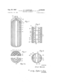
- FIGURE 1 is a longitudinal cross-sectional view through a container housing according to this invention.
- FIGURE 2 is a partial cross-sectional view of a modified form of container
- FIGURE 2a is a similar View of another modified form of container
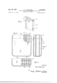
- FIGURE 3 is a longitudinal cross-sectional view through a further modified form of container
- FIGURE 4 is a cross-sectional view taken on the line 4-4 of FIGURE 3;
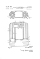
- FIGURE 5 is a perspective view of a container according to this invention.
- FIGURE 6 is a front elevational view partially cut away of a further form of the container
- FIGURE 7 is a cross-sectional view taken on the line 77 of FIGURE 6;
- FIGURE 8 is a view partly in cross-section taken on the line 8-8 of FIGURE 7;
- FIGURE 9 is a cross-sectional view through a further modified form of the invention.
- FIGURE 10 is a cross-sectional view taken on the line 1010 of FIGURE 9.
- the bottle-like container housing 1 is separated by partitions 2 into a plurality of compartments 3 extending in the direction of the longitudinal axis of the housing.
- Partitions 2 are integral With the housing. Openings 4 in partitions 2 place the compart l g ments in communication with each other. Compartment communicates through passageway 6 in the housing cap 7 with a central passageway 8, the latter extending from the gas entrance opening 9 to the center compartment 10.
- the partitions can be arranged to form different type compartments.
- three groups of compartments 11, 12 and 13 extend radially from the center of the housing to form rows of compartments concentric with the center compartment 10.
- the compartments become smaller in crosssectional area from the center of the housing to the circumference of the housing.
- the partitions 2 adjacent the center of the housing can be made thinner and of less tensile strength than the outer Wall 14 of the container.
- One of the partitions 2 adjacent the center of the housing is extended into a wedge-shaped end piece 15 to form a dovetail joint 16 in the cap 7.
- This means that the pressure container is assembled from a plurality of members which are later welded together if made of synthetic material.
- the portion 17 of the triangular partition is used to form a cylindrical compartment 18.
- compartments 10, 19 and 20 are all of cylindrical shape with diameters which decrease radially outward of the center of the housing.
- the partitions between compartments 10, 19 and 20 are thinner than the exterior wall 14.
- the cylindrical housing 21 is provided with transverse radially extending partitions 22, as well as with the partitions 23 and 24 which are concentric with the longitudinal axis of the housing, and which are joined to the transverse partitions 22. Furthermore, thecompartments formed by partitions 23 and 24 are sub-divided by transverse circular partitions 25. Likewise, the compartments between partitions 23 and peripheral compartment 26 are further sub-divided by circular ring partitions 27. Openings 28 in the transverse partitions provide for gas communication between the compartments. The compartmented housing thus formed is then enclosed in an outer metal or plastic jacket 29 which encloses a large number of compartments.
- the pressure exerted upon the jacket 29 in the direction of the arrow 30, FIGURE 4, is exerted on only a small portion of the surface.
- the pressure at right angles in the direction of the arrow 31 is, because of the numerous compartments, only effective on a small portion of the wall surface.
- FIGURE 5 shows a safety breathing apparatus in which the pressure gas container is composed of a housing 32 slightly curved when seen in cross-section. Other details of the safety breathing apparatus are not shown. 0n the housing, however, are belt fastening eyes 33 which are integral with the housing and through which the carrying belt or straps are threaded. Preferably these eyes are made by depressions in the housing which are bridged by crosspieces. Perforations 34 are openings for the exhaled air and breathing tube 35 leads to the face mask. Perforations 34 are omitted when this is a pressure gas container for a closed breathing sys- Housing 32 is partitioned into separate compartments. These partitions are formed depending upon the molding technique used if the container is made of molded pieces.
- the housing 32 is made of an upper member 36 and a lower member 37 with compartments 38 of oval-shaped cross-section in the center of the housing and cylindrical compartments 39 adjacent the outer wall of the housing. These compartments extendparallel to the longitudinal axis of the housing. Pegs 40 fastened in the partitions in lower member 36 extend into corresponding openings in upper member 36.
- pegs 40 can be glued or welded to upper member 36.
- the upper and lower members are connected by a joint 41 so that the compartments in the upper and lower members are aligned. This also facilitates the molding of the two members.
- Joint 41 may be a telescoped or lapped joint so that the two members are joined by a large connecting surface.
- FIGURES 9 and 10 A container for a closed system breathing apparatus is shown in FIGURES 9 and 10 and in which the exhaled air passes through a granular filter for the absorption of the carbon dioxide.
- a compartment 42 for the carbon dioxide absorbing material In the center of the container is a compartment 42 for the carbon dioxide absorbing material. On either side of this center compartment are housings 43 and 44 which are sub-divided into compartments for receiving the pressure gas. Alternatively, the positions of thecarbon dioxide absorption material and the pressure gas can be reversed.
- the container is composed of a synthetic material or a light metal alloy.
- the innermost compartments 45 are of larger cross-sectional area than the outer compartments 46.
- the upper wall 47 of compartment 42 has an opening surrounded by a collar 48 to which is fastened the flexible breathing tube 49 which is folded into the pocket 50. This pocket is closed by an easily removable cover 51.
- Tube 49 has a mouthpiece 52.
- housings 43 and 44 are closed by a sealing partition 53 and means are provided for the pipe lines connecting the compartments 45 and 46.
- a transverse wall 54 is made of metal and bored to form the pipe lines between the individual compartments. This wall is also provided with fittings, such as lung control valve 55 and the gas pressure reducer 56. The latter communicates with the pipe lines or bores in wall 54. Also wall 54 contains a pipe line bore running from the gas pressure reducer 56 to the collar 57. A breathing.
- cover 59 is easily removable so that, when the apparatus is used, the cover candbe pulled off and the breathing bag allowed to expan
- the housing for the pressure container is made of a material which can be sprayed into a mold, the ar rangement of the partitions forming the compartments is important.
- polyester resins strengthened with fiber glass, individual fiber glass mats, note FIGURE 8 can be stacked into the mold cores for forming the individual compartments 38 and 39 so that a thorough saturation of the fiber glass by the synthetic resin is obtained. This produces a very stable structure.
- the individual mold cores for the compartments are surrounded with cords of fiber glass so that the peripheral walls of the housing are anchored to the center portion of the housing. This construction prevents outward bulging of the compartments and a stretching of the synthetic material.
- the pressure gas housings shown in the other figures can also be provided with a gas charging valve.
- a gas charging valve In apparatuses using lung-controlled valves, it is not necessary to use a shut-off valve as this would only open during the breathing cycle.
- the individual come partments are assembled so that only one opening is.
- a gas feed valve would be provided at this point.
- the pressure gas container of this invention has the advantages in weight savings and the ability to be of such form that all the breathing apparatus fittings can be stored in the container without appreciable loss of space.
- the gas pipe passageways can be formed in the housing by means of bores and the like so that no extraneous tubing is necessary.
- the pressure gas receiving compartments can be arranged to save space according to the final desired shape of the container.
- a pressure gas container as for a portable safety breathing apparatus comprising a housing, integrally formed partitions in said housing forming a plurality of intercommunicating compartments, said compartments nearer the center of said housing having a larger volume than the compartments further from said center for giving the compartments further from said center a lower pressure load per unit of wall area than the compartments nearer said center, said housing being formed from substances selected from the class consisting of synthetic materials and light metals, said housing being curved to form one concave side adapted to fit the body of a user of the container, at least one pocket in said housing, a lung-controlled valve connected to said compartment and positioned in said pocket, a gas reducing valve joined to said lung-controlled valve in said pocket, a breathing 6 tube pocket in said housing, a breathing tube in said breathing tube pocket and communicating with said lungcontrolled valve, and an easily removable cover for said breathing tube pocket.
- each eye comprising a depression in the surface of said housing, and a cross piece bridging said depression.
- a container as in claim 4 said housing comprising a plurality of compartmented members assembled with the respective compartments aligned.
Description
3,338,238 SAFETY E. A. WARNCKE PRESSURE GAS STORAGE. CONTAINER AND Aug. 29. 1967 BREATHING APPARATUS Filed Dec. 16, 1963 3 Sheets-Sheet 1 INVENTOR fr'nsz Wafincke I BY M ATTOR ZM E. A. WARNCKE 3,338,238 PRESSURE GAS STORAGE CONTAINER AND SAFETY Aug. 29, 1 967 BREATHING APPARATUS 3 Sheets-Sheet 2 Filed Dec. 16, 1963 Erhsz War'ncK e Aug. 29, 1967 PRESSURE GAS STORAGE CONTAINER AND SAFETY BREATHING APPARATUS Filed Dec. 16, I963 3 Sheets-Sheet 5 /IIII lI",
T v Z24 v M l IIII i 45\17 4 46 1} A T I J ii INVENTOR .10 I i Q w 7 Ir'nsz Warncke @AJTTORNS E. A. WA RNCKE 3,338,238
Patented Aug. 29,- 1967 3,338,238 PRESSURE GAS STORAGE CONTAINER AND SAFETY BREATHING APPARATUS Ernst A. Warncke, Lubeck, Germany, assignor to Otto Heinrich Drager, Lubeck, Germany Filed Dec. 16, 1963, Ser. No. 330,704 Claims priority, application Germany, Dec. 24, 1962, D 40,620 6 Claims. (Cl. 128142.2)
ABSTRACT OF THE DISCLOSURE A multicell container for a breathing apparatus distributes the unit gas pressure on the cell walls and provides a housing for a breathing bag and its accessories.
This invention relates to a safety breathing device and, in particular, to .a pressure gas storage container for such device.
Safety breathing apparatuses are, in most cases, provided with a pressure gas storage container, which along with the apparatus itself, is carried by a person. The pressure gas container for high pressure air or oxygen is composed of a light metal, such as aluminum, and is installed in a portable frame along with the other fittings for the device. These devices have the disadvantage in that the pressure gas containers or bottles are relatively heavy. This weight is due to the metal required to make the bottle strong enough to Withstand the high internal gas pressures. This disadvantage particularly applies with respect to the weight required for a pressure gas container since such a container needs a substantially larger amount of pressure gas when used with .a pressure gas apparatus as compared to devices using high pressure oxygen alone.
The object of this invention is to avoid the disadvan-' tages of the heretofore known pressure gas containers for safety breathing devices.
In general, the invention comprises :a block of material forming a housing and having cell-like hollow spaces which communicate with one another. The housing block is made of a synthetic material, a light metal or the like. The advantage gained in this invention is that the walls of the pressure gas housing or block can be made substantially thinner as the surface load or the pressure on the walls is quite low.
Another feature of this invention lies in that the celllike hollow spaces or compartments are given such a size or -a wall surface area that when they are positioned adjacent the circumference of the housing they are subject to less wall pressure loads than the compartments adjacent the center of the housing. Accordingly, the compartments adjacent the center of the housing can be larger in volume than those lying adjacent the periphery of the housing. This type of construction has certain advantages. First, the partitions forming the compartments adjacent the center of the housing are not subjected to any differential gas pressure since they are under the same pressure on all sides. These partitions are relatively thin as they are only essentially subject to tension in resisting the outward gas pressure on the circumferential wall of the housing. Moreover, when the compartments lyin-g adjacent the circumference of the housing are of small volume, the stresses on each unit of Wall surface are small. Accordingly, the advantage is obtained of making pressure gas containers of synthetic material and charging them with relatively high gas pressures. Because of the compartmented structure, the exterior walls of the housing are tied together by the partitions to resist the gas pressure on the outer walls.
Other advantages result, in turn, in that the container does not have to be in the customary form of a sphere, a cylinder, or the like. According to this invention, the pressure gas container can have other forms. For example, the pressure gas container can be shaped to conform to the body of a user of the container.
Again, the pressure gas container can be provided with large pockets into which various fittings of the apparatus can be inserted, such as the gas reducing valve, lung control valve, manometer, and the like. This avoids the'need for a separate container. These pockets are provided with screws, spring clips, bayonet joint connections and the like for securing the inserted fittings.
The pockets containing removable parts, such as a face mask, mouthpiece and breathing tube, are closed by an easily removable cover.
When the apparatus is in the form of a closed breathing system, the housing includes a compartment which will receive a chemical material for absorbing carbon dioxide.
The housing of this invention is also provided on its exterior surface with belt fastening eyes or hooks which are integral with and composed of the same material as the housing.
The pressure gas housing is made in several different ways. For example, it can be composed of several separate members, each of which has compartments and with the compartments aligned in the assembled members. Accordingly, these members can be molded of or otherwise made of synthetic material, light metal, or the like and later assembled into the final container. Thus a desirable and quick fabrication of the composite members is achieved. The individual members can be glued or welded together. Suitable synthetic materials for this invention are polyester resins strengthened with fiber glass, polyamides, polyethylene or the like.
According to another feature of the invention, the pressure gas housing is suurounded by a jacket of another type of material, such as a metal jacket.
The means by which the objects of the invention are obtained are described more fully with reference to the accompanying drawings in which:
FIGURE 1 is a longitudinal cross-sectional view through a container housing according to this invention;
FIGURE 2 is a partial cross-sectional view of a modified form of container; 7
FIGURE 2a is a similar View of another modified form of container;
FIGURE 3 is a longitudinal cross-sectional view through a further modified form of container;
FIGURE 4 is a cross-sectional view taken on the line 4-4 of FIGURE 3;
FIGURE 5 is a perspective view of a container according to this invention;
FIGURE 6 is a front elevational view partially cut away of a further form of the container;
FIGURE 7 is a cross-sectional view taken on the line 77 of FIGURE 6;
FIGURE 8 is a view partly in cross-section taken on the line 8-8 of FIGURE 7;
FIGURE 9 is a cross-sectional view through a further modified form of the invention; and
FIGURE 10 is a cross-sectional view taken on the line 1010 of FIGURE 9.
As shown in FIGURE 1, the bottle-like container housing 1 is separated by partitions 2 into a plurality of compartments 3 extending in the direction of the longitudinal axis of the housing. Partitions 2 are integral With the housing. Openings 4 in partitions 2 place the compart l g ments in communication with each other. Compartment communicates through passageway 6 in the housing cap 7 with a central passageway 8, the latter extending from the gas entrance opening 9 to the center compartment 10.
As shown in FIGURES 2 and 2a, the partitions can be arranged to form different type compartments. In FIG- URE 2, three groups of compartments 11, 12 and 13 extend radially from the center of the housing to form rows of compartments concentric with the center compartment 10. The compartments become smaller in crosssectional area from the center of the housing to the circumference of the housing. The partitions 2 adjacent the center of the housing can be made thinner and of less tensile strength than the outer Wall 14 of the container.
One of the partitions 2 adjacent the center of the housing is extended into a wedge-shaped end piece 15 to form a dovetail joint 16 in the cap 7. This means that the pressure container is assembled from a plurality of members which are later welded together if made of synthetic material. As shown in FIGURE 2, the portion 17 of the triangular partition is used to form a cylindrical compartment 18.
In FIGURE 2a, the compartments 10, 19 and 20 are all of cylindrical shape with diameters which decrease radially outward of the center of the housing. Here again the partitions between compartments 10, 19 and 20 are thinner than the exterior wall 14.
In FIGURES 3 and 4, the cylindrical housing 21 is provided with transverse radially extending partitions 22, as well as with the partitions 23 and 24 which are concentric with the longitudinal axis of the housing, and which are joined to the transverse partitions 22. Furthermore, thecompartments formed by partitions 23 and 24 are sub-divided by transverse circular partitions 25. Likewise, the compartments between partitions 23 and peripheral compartment 26 are further sub-divided by circular ring partitions 27. Openings 28 in the transverse partitions provide for gas communication between the compartments. The compartmented housing thus formed is then enclosed in an outer metal or plastic jacket 29 which encloses a large number of compartments. The pressure exerted upon the jacket 29 in the direction of the arrow 30, FIGURE 4, is exerted on only a small portion of the surface. The pressure at right angles in the direction of the arrow 31 is, because of the numerous compartments, only effective on a small portion of the wall surface.
FIGURE 5 shows a safety breathing apparatus in which the pressure gas container is composed of a housing 32 slightly curved when seen in cross-section. Other details of the safety breathing apparatus are not shown. 0n the housing, however, are belt fastening eyes 33 which are integral with the housing and through which the carrying belt or straps are threaded. Preferably these eyes are made by depressions in the housing which are bridged by crosspieces. Perforations 34 are openings for the exhaled air and breathing tube 35 leads to the face mask. Perforations 34 are omitted when this is a pressure gas container for a closed breathing sys- Housing 32 is partitioned into separate compartments. These partitions are formed depending upon the molding technique used if the container is made of molded pieces.
As shown, the housing 32 is made of an upper member 36 and a lower member 37 with compartments 38 of oval-shaped cross-section in the center of the housing and cylindrical compartments 39 adjacent the outer wall of the housing. These compartments extendparallel to the longitudinal axis of the housing. Pegs 40 fastened in the partitions in lower member 36 extend into corresponding openings in upper member 36.
The outer ends of these pegs can be pressed fiat in the manner of rivets. Furthermore, pegs 40 can be glued or welded to upper member 36.
The upper and lower members are connected by a joint 41 so that the compartments in the upper and lower members are aligned. This also facilitates the molding of the two members.
Other shapes can be used for the compartments and fo l the housing and the upper and lower members can be made of the same or different sizes, all depending upon the molding technique used. Joint 41 may be a telescoped or lapped joint so that the two members are joined by a large connecting surface.
A container for a closed system breathing apparatus is shown in FIGURES 9 and 10 and in which the exhaled air passes through a granular filter for the absorption of the carbon dioxide.
In the center of the container is a compartment 42 for the carbon dioxide absorbing material. On either side of this center compartment are housings 43 and 44 which are sub-divided into compartments for receiving the pressure gas. Alternatively, the positions of thecarbon dioxide absorption material and the pressure gas can be reversed. The container is composed of a synthetic material or a light metal alloy.
In the pressure gas housing, the innermost compartments 45 are of larger cross-sectional area than the outer compartments 46.
The upper wall 47 of compartment 42 has an opening surrounded by a collar 48 to which is fastened the flexible breathing tube 49 which is folded into the pocket 50. This pocket is closed by an easily removable cover 51. Tube 49 has a mouthpiece 52.
The lower ends of housings 43 and 44 are closed by a sealing partition 53 and means are provided for the pipe lines connecting the compartments 45 and 46. A transverse wall 54 is made of metal and bored to form the pipe lines between the individual compartments. This wall is also provided with fittings, such as lung control valve 55 and the gas pressure reducer 56. The latter communicates with the pipe lines or bores in wall 54. Also wall 54 contains a pipe line bore running from the gas pressure reducer 56 to the collar 57. A breathing.
bag 58 is folded into the pocket formed by the cover 59 and is attached to collar 57. This cover protects the breathing bag when not in use. Also, cover 59 is easily removable so that, when the apparatus is used, the cover candbe pulled off and the breathing bag allowed to expan When the housing for the pressure container is made of a material which can be sprayed into a mold, the ar rangement of the partitions forming the compartments is important. When using polyester resins strengthened with fiber glass, individual fiber glass mats, note FIGURE 8, can be stacked into the mold cores for forming the individual compartments 38 and 39 so that a thorough saturation of the fiber glass by the synthetic resin is obtained. This produces a very stable structure. In another form of construction, the individual mold cores for the compartments are surrounded with cords of fiber glass so that the peripheral walls of the housing are anchored to the center portion of the housing. This construction prevents outward bulging of the compartments and a stretching of the synthetic material.
The pressure gas housings shown in the other figures can also be provided with a gas charging valve. In apparatuses using lung-controlled valves, it is not necessary to use a shut-off valve as this would only open during the breathing cycle.
In another form of the invention, the individual come partments are assembled so that only one opening is.
provided at the entrance to the pressure reducer and/ or lung-controlled valve so that this opening can be shut off by a valve positioned within the housing composed of synthetic material. Here again, a gas feed valve would be provided at this point.
While the preferred forms of forming the housing are shown herein, many other forms are possible and which result from the type of technique of fabrication employed, especially molding techniques.
The pressure gas container of this invention has the advantages in weight savings and the ability to be of such form that all the breathing apparatus fittings can be stored in the container without appreciable loss of space. In many instances, the gas pipe passageways can be formed in the housing by means of bores and the like so that no extraneous tubing is necessary. The pressure gas receiving compartments can be arranged to save space according to the final desired shape of the container.
Having now described the means by which the objects of the invention are obtained,
I claim:
1. A pressure gas container as for a portable safety breathing apparatus comprising a housing, integrally formed partitions in said housing forming a plurality of intercommunicating compartments, said compartments nearer the center of said housing having a larger volume than the compartments further from said center for giving the compartments further from said center a lower pressure load per unit of wall area than the compartments nearer said center, said housing being formed from substances selected from the class consisting of synthetic materials and light metals, said housing being curved to form one concave side adapted to fit the body of a user of the container, at least one pocket in said housing, a lung-controlled valve connected to said compartment and positioned in said pocket, a gas reducing valve joined to said lung-controlled valve in said pocket, a breathing 6 tube pocket in said housing, a breathing tube in said breathing tube pocket and communicating with said lungcontrolled valve, and an easily removable cover for said breathing tube pocket.
2. A container as in claim 1, further comprising a carbon dioxide absorption material compartment in said housing communicating with said breathing tube.
3. A container as in claim 2, further comprising at least one belt holding eye integrally formed on the exterior surface of said housing.
4. A container as in claim 3, each eye comprising a depression in the surface of said housing, and a cross piece bridging said depression.
5. A container as in claim 4, said housing comprising a plurality of compartmented members assembled with the respective compartments aligned.
6. A container as in claim 5, further comprising a metal jacket around said housing.
References Cited UNITED STATES PATENTS 3,044,654 7/1962 Creighton 220-3 3,069,042 12/1962 Johnston 220-22 X 3,166,212 1/1965 Resos 220 23.4
FOREIGN PATENTS 891,497 9/1953 Germany.
OTHER REFERENCES German printed application Dl3709, June 1956.
RICHARD A. GAUDET, Primary Examiner.
W. E. KAMM, Assistant Examiner,
Claims (1)
1. A PRESSURE GAS CONTAINER AS FOR A PORTABLE SAFETY BREATHING APPARATUS COMPRISING A HOUSINS, INTEGRALLY FORMED PARTITIONS IN SAID HOUSING FORMING A PLURALITY OF INTERCOMMUNICATING COMPARTMENTS, SAID COMPARTMENTS NEARER THE CENTER OF SAID HOUSING HAVING A LARGER VOLUME THAN THE COMPARTMENTS FURTHER FROM SAID CENTER FOR GIVING THE COMPARTMENTS FURTHER FROM SAID CENTER A LOWER PRESSURE LOAD PER UNIT OF WALL AREA THAN THE COMPARTMENTS NEARER SAID CENTER, SAID HOUSING BEING FORMED FROM SUBSTANCES SELECTED FROM THE CLASS CONSISTING OF SYNTHETIC MATERIALS AND LIGHT METALS, SAID HOUSING BEING CURVED TO
Applications Claiming Priority (1)
| Application Number | Priority Date | Filing Date | Title |
|---|---|---|---|
| DED40620A DE1253054B (en) | 1962-12-24 | 1962-12-24 | Pressurized gas storage container for breathing apparatus |
Publications (1)
| Publication Number | Publication Date |
|---|---|
| US3338238A true US3338238A (en) | 1967-08-29 |
Family
ID=7045543
Family Applications (1)
| Application Number | Title | Priority Date | Filing Date |
|---|---|---|---|
| US330704A Expired - Lifetime US3338238A (en) | 1962-12-24 | 1963-12-16 | Pressure gas storage container and safety breathing apparatus |
Country Status (4)
| Country | Link |
|---|---|
| US (1) | US3338238A (en) |
| DE (1) | DE1253054B (en) |
| GB (1) | GB1030999A (en) |
| NL (1) | NL302301A (en) |
Cited By (42)
| Publication number | Priority date | Publication date | Assignee | Title |
|---|---|---|---|---|
| US3837527A (en) * | 1973-03-16 | 1974-09-24 | L Kutik | Reinforced aerosol container |
| US4101998A (en) * | 1976-04-14 | 1978-07-25 | Buckle Brian L | Buoyancy control apparatus for divers |
| US4165012A (en) * | 1977-12-07 | 1979-08-21 | Philip Morris Incorporated | Filler for pressure vessel |
| US4168289A (en) * | 1977-12-19 | 1979-09-18 | Saunion Oscar P | Floatless carburetor |
| US4253454A (en) * | 1976-10-05 | 1981-03-03 | Dragerwerk Aktiengesellschaft | Respirator package for carrying on a person |
| US4566589A (en) * | 1983-03-04 | 1986-01-28 | Udo Poschinger | Gas container |
| US4570813A (en) * | 1982-12-16 | 1986-02-18 | L. & C. Steinmuller Gmbh | Connection anchor for liner of cast iron pressure tank |
| US4964405A (en) * | 1989-09-01 | 1990-10-23 | E. I. Du Pont De Nemours And Company | Emergency respiration apparatus |
| US5036845A (en) * | 1989-04-14 | 1991-08-06 | Scholley Frank G | Flexible container for compressed gases |
| US5127399A (en) * | 1989-04-14 | 1992-07-07 | Scholley Frank G | Flexible container for compressed gases |
| US5239989A (en) * | 1990-06-13 | 1993-08-31 | Chen Chin S | Safety device |
| US5435305A (en) * | 1993-05-24 | 1995-07-25 | Rankin, Sr.; Pleasant P. | Emergency air supply pack |
| US5518140A (en) * | 1994-11-07 | 1996-05-21 | Cryenco, Inc. | Liquified gas storage tank overfill protection system and method |
| US5564587A (en) * | 1991-12-23 | 1996-10-15 | Falk; Ingemar | Pressure container |
| US5927537A (en) * | 1994-08-08 | 1999-07-27 | Falk; Ingemar | Pressure container |
| US6047860A (en) * | 1998-06-12 | 2000-04-11 | Sanders Technology, Inc. | Container system for pressurized fluids |
| EP0997681A2 (en) * | 1998-10-28 | 2000-05-03 | Linde Aktiengesellschaft | Storage vessel for liquified gases |
| WO2001007792A1 (en) | 1999-07-26 | 2001-02-01 | Tapco International, Inc. | Improved assembly of orifice chambers |
| US6188840B1 (en) * | 1996-05-31 | 2001-02-13 | Perstorp Ab | Process for the manufacturing of a pressure vessel and a pressure vessel, especially for a water heater, made by the process |
| US6345730B1 (en) | 2000-06-13 | 2002-02-12 | Mallinckrodt Inc. | Adhesively connected polymeric pressure chambers and method for making the same |
| US6412484B1 (en) | 2000-06-13 | 2002-07-02 | Mallinckrodt Inc. | Fluid control valve for pressure vessel |
| US6453920B1 (en) | 2000-11-08 | 2002-09-24 | Mallinckrodt Inc. | Walking assistance device incorporating gas storage vessel comprising a polymeric container system for pressurized fluids |
| FR2825974A1 (en) * | 2001-06-14 | 2002-12-20 | Salomon Sa | Diving system comprises compressed gas reservoir comprising compartment made from casing with heads at each end connected by tie rods |
| US6502571B1 (en) | 2000-06-13 | 2003-01-07 | Mallinckrodt Inc. | High pressure fitting with dual locking swaging mechanism |
| US6510850B1 (en) | 2000-11-08 | 2003-01-28 | Mallinckrodt Inc. | Emergency breathing apparatus incorporating gas storage vessel comprising a polymeric container system for pressurized fluids |
| US6513523B1 (en) | 2000-11-08 | 2003-02-04 | Mallinckrodt Inc. | Wearable belt incorporating gas storage vessel comprising a polymeric container system for pressurized fluids |
| US6513522B1 (en) | 2000-06-13 | 2003-02-04 | Mallinckrodt Inc. | Wearable storage system for pressurized fluids |
| US6527075B1 (en) | 2000-11-08 | 2003-03-04 | Mallinckrodt Inc. | Vehicle incorporating gas storage vessel comprising a polymeric container system for pressurized fluids |
| US6526968B1 (en) | 2000-11-08 | 2003-03-04 | Mallinckrodt Inc. | Utility belt incorporating a gas storage vessel |
| US6536425B1 (en) | 2000-11-01 | 2003-03-25 | Mallinckrodt Inc. | Litter incorporating gas storage vessel comprising a polymeric container system for pressurized fluids |
| US6651659B2 (en) | 2001-05-23 | 2003-11-25 | John I. Izuchukwu | Ambulatory storage system for pressurized gases |
| US20040118397A1 (en) * | 2002-12-23 | 2004-06-24 | Swann Linsey J. | Personal disposable emergency breathing system with radial flow |
| US20050092756A1 (en) * | 2003-09-01 | 2005-05-05 | Goggin Brian A. | Storage vessel |
| US20060060149A1 (en) * | 2004-09-23 | 2006-03-23 | Response Engineering, Inc. | Spill-resistant drinking container for animals |
| US20080283419A1 (en) * | 2007-05-04 | 2008-11-20 | Veksler Mark D | Reduced-weight container and/or tube for compressed gases and liquids |
| US20120067348A1 (en) * | 2010-03-24 | 2012-03-22 | Steck Jeremy A | Breathing apparatus system |
| US20140069427A1 (en) * | 2011-03-18 | 2014-03-13 | Draeger Safety Uk Limited | Harness for breathing apparatus |
| US20140224252A1 (en) * | 2011-03-18 | 2014-08-14 | Draeger Safety Uk Limited | Harness for breating apparatus |
| WO2014191810A1 (en) | 2013-05-31 | 2014-12-04 | Sam Outillage | Method and device for supplying a hand-held pneumatic tool with a pressurised fluid, in particular compressed air, from a source of such a fluid, in particular a portable bottle |
| US9650195B2 (en) | 2014-10-24 | 2017-05-16 | H2Safe, Llc | Fail-safe containment device for containing volatile fluids |
| CN111188995A (en) * | 2020-03-16 | 2020-05-22 | 安徽伯华氢能源科技有限公司 | Multi-stage high-pressure hydrogen storage container and hydrogen storage method |
| US11306872B2 (en) * | 2013-02-08 | 2022-04-19 | Loukus Technologies, Inc. | Core structured components, containers, and methods of casting |
Families Citing this family (7)
| Publication number | Priority date | Publication date | Assignee | Title |
|---|---|---|---|---|
| GB2165343A (en) * | 1984-10-04 | 1986-04-09 | Graviner Ltd | Storing gas |
| US5582027A (en) * | 1994-03-29 | 1996-12-10 | Nippondenso Co., Ltd. | Modulator integrated type refrigerant condenser |
| DE19704968C2 (en) * | 1997-01-28 | 1999-06-02 | Mannesmann Ag | Container for storing compressed gas |
| SE524864C2 (en) * | 2002-12-02 | 2004-10-12 | Maria Palmquist | Device |
| JP4436148B2 (en) * | 2004-02-09 | 2010-03-24 | 本田技研工業株式会社 | Pressure vessel liner and method of manufacturing the same |
| WO2012073024A2 (en) * | 2010-12-02 | 2012-06-07 | Draeger Safety Uk Limited | Case for breathing apparatus and cooling unit for breathing apparatus |
| DE102020116457A1 (en) | 2020-06-23 | 2021-12-23 | Audi Aktiengesellschaft | Gas pressure accumulator, fuel cell device and fuel cell vehicle |
Citations (4)
| Publication number | Priority date | Publication date | Assignee | Title |
|---|---|---|---|---|
| DE891497C (en) * | 1942-08-08 | 1953-09-28 | Draegerwerk Ag | Closed oxygen breathing apparatus with freshening of the exhaled air |
| US3044654A (en) * | 1958-07-01 | 1962-07-17 | Bendix Corp | High pressure vessel |
| US3069042A (en) * | 1961-07-06 | 1962-12-18 | Herrick L Johnston Inc | Method and apparatus for storing liquefied gases |
| US3166212A (en) * | 1962-09-04 | 1965-01-19 | North American Aviation Inc | Segmented tanks |
Family Cites Families (2)
| Publication number | Priority date | Publication date | Assignee | Title |
|---|---|---|---|---|
| DE709405C (en) * | 1933-06-08 | 1941-08-15 | Bernh Draeger | Reservoir for the high-tension oxygen to be carried in airplanes, airships or free balloons |
| DE658447C (en) * | 1935-10-15 | 1938-04-02 | Franz Pfeffer | Container for high tension gases and liquids |
-
0
- NL NL302301D patent/NL302301A/xx unknown
-
1962
- 1962-12-24 DE DED40620A patent/DE1253054B/en active Pending
-
1963
- 1963-12-16 US US330704A patent/US3338238A/en not_active Expired - Lifetime
- 1963-12-24 GB GB50835/63A patent/GB1030999A/en not_active Expired
Patent Citations (4)
| Publication number | Priority date | Publication date | Assignee | Title |
|---|---|---|---|---|
| DE891497C (en) * | 1942-08-08 | 1953-09-28 | Draegerwerk Ag | Closed oxygen breathing apparatus with freshening of the exhaled air |
| US3044654A (en) * | 1958-07-01 | 1962-07-17 | Bendix Corp | High pressure vessel |
| US3069042A (en) * | 1961-07-06 | 1962-12-18 | Herrick L Johnston Inc | Method and apparatus for storing liquefied gases |
| US3166212A (en) * | 1962-09-04 | 1965-01-19 | North American Aviation Inc | Segmented tanks |
Cited By (51)
| Publication number | Priority date | Publication date | Assignee | Title |
|---|---|---|---|---|
| US3837527A (en) * | 1973-03-16 | 1974-09-24 | L Kutik | Reinforced aerosol container |
| US4101998A (en) * | 1976-04-14 | 1978-07-25 | Buckle Brian L | Buoyancy control apparatus for divers |
| US4253454A (en) * | 1976-10-05 | 1981-03-03 | Dragerwerk Aktiengesellschaft | Respirator package for carrying on a person |
| US4165012A (en) * | 1977-12-07 | 1979-08-21 | Philip Morris Incorporated | Filler for pressure vessel |
| US4168289A (en) * | 1977-12-19 | 1979-09-18 | Saunion Oscar P | Floatless carburetor |
| US4570813A (en) * | 1982-12-16 | 1986-02-18 | L. & C. Steinmuller Gmbh | Connection anchor for liner of cast iron pressure tank |
| US4566589A (en) * | 1983-03-04 | 1986-01-28 | Udo Poschinger | Gas container |
| US5036845A (en) * | 1989-04-14 | 1991-08-06 | Scholley Frank G | Flexible container for compressed gases |
| US5127399A (en) * | 1989-04-14 | 1992-07-07 | Scholley Frank G | Flexible container for compressed gases |
| US4964405A (en) * | 1989-09-01 | 1990-10-23 | E. I. Du Pont De Nemours And Company | Emergency respiration apparatus |
| US5239989A (en) * | 1990-06-13 | 1993-08-31 | Chen Chin S | Safety device |
| US5564587A (en) * | 1991-12-23 | 1996-10-15 | Falk; Ingemar | Pressure container |
| US5704512A (en) * | 1991-12-23 | 1998-01-06 | Falk; Ingemar | Vessel |
| US5435305A (en) * | 1993-05-24 | 1995-07-25 | Rankin, Sr.; Pleasant P. | Emergency air supply pack |
| US5927537A (en) * | 1994-08-08 | 1999-07-27 | Falk; Ingemar | Pressure container |
| US5518140A (en) * | 1994-11-07 | 1996-05-21 | Cryenco, Inc. | Liquified gas storage tank overfill protection system and method |
| US6188840B1 (en) * | 1996-05-31 | 2001-02-13 | Perstorp Ab | Process for the manufacturing of a pressure vessel and a pressure vessel, especially for a water heater, made by the process |
| US6047860A (en) * | 1998-06-12 | 2000-04-11 | Sanders Technology, Inc. | Container system for pressurized fluids |
| EP0997681A2 (en) * | 1998-10-28 | 2000-05-03 | Linde Aktiengesellschaft | Storage vessel for liquified gases |
| EP0997681A3 (en) * | 1998-10-28 | 2008-03-19 | Linde Aktiengesellschaft | Storage vessel for liquified gases |
| US6367647B1 (en) * | 1998-10-28 | 2002-04-09 | Linde Akteingesellschaft | Storage container for liquefied gases |
| WO2001007792A1 (en) | 1999-07-26 | 2001-02-01 | Tapco International, Inc. | Improved assembly of orifice chambers |
| US6345730B1 (en) | 2000-06-13 | 2002-02-12 | Mallinckrodt Inc. | Adhesively connected polymeric pressure chambers and method for making the same |
| US6412484B1 (en) | 2000-06-13 | 2002-07-02 | Mallinckrodt Inc. | Fluid control valve for pressure vessel |
| US6502571B1 (en) | 2000-06-13 | 2003-01-07 | Mallinckrodt Inc. | High pressure fitting with dual locking swaging mechanism |
| US6513522B1 (en) | 2000-06-13 | 2003-02-04 | Mallinckrodt Inc. | Wearable storage system for pressurized fluids |
| US6536425B1 (en) | 2000-11-01 | 2003-03-25 | Mallinckrodt Inc. | Litter incorporating gas storage vessel comprising a polymeric container system for pressurized fluids |
| US6453920B1 (en) | 2000-11-08 | 2002-09-24 | Mallinckrodt Inc. | Walking assistance device incorporating gas storage vessel comprising a polymeric container system for pressurized fluids |
| US6510850B1 (en) | 2000-11-08 | 2003-01-28 | Mallinckrodt Inc. | Emergency breathing apparatus incorporating gas storage vessel comprising a polymeric container system for pressurized fluids |
| US6513523B1 (en) | 2000-11-08 | 2003-02-04 | Mallinckrodt Inc. | Wearable belt incorporating gas storage vessel comprising a polymeric container system for pressurized fluids |
| US6527075B1 (en) | 2000-11-08 | 2003-03-04 | Mallinckrodt Inc. | Vehicle incorporating gas storage vessel comprising a polymeric container system for pressurized fluids |
| US6526968B1 (en) | 2000-11-08 | 2003-03-04 | Mallinckrodt Inc. | Utility belt incorporating a gas storage vessel |
| US6651659B2 (en) | 2001-05-23 | 2003-11-25 | John I. Izuchukwu | Ambulatory storage system for pressurized gases |
| FR2825974A1 (en) * | 2001-06-14 | 2002-12-20 | Salomon Sa | Diving system comprises compressed gas reservoir comprising compartment made from casing with heads at each end connected by tie rods |
| WO2002102657A1 (en) * | 2001-06-14 | 2002-12-27 | Salomon S.A. | Diving system with an improved reservoir |
| US6761162B1 (en) * | 2002-12-23 | 2004-07-13 | Brookdale International Systems, Inc. | Personal disposable emergency breathing system with radial flow |
| US20040118397A1 (en) * | 2002-12-23 | 2004-06-24 | Swann Linsey J. | Personal disposable emergency breathing system with radial flow |
| US8561827B2 (en) | 2003-09-01 | 2013-10-22 | H2Safe, Llc | Storage vessel chamber for storing fuels such as hydrogen |
| US7694840B2 (en) | 2003-09-01 | 2010-04-13 | H2Safe, Llc | Storage vessel chamber for storing fuels such as hydrogen |
| US20050092756A1 (en) * | 2003-09-01 | 2005-05-05 | Goggin Brian A. | Storage vessel |
| US20060060149A1 (en) * | 2004-09-23 | 2006-03-23 | Response Engineering, Inc. | Spill-resistant drinking container for animals |
| US20080283419A1 (en) * | 2007-05-04 | 2008-11-20 | Veksler Mark D | Reduced-weight container and/or tube for compressed gases and liquids |
| US9061788B2 (en) * | 2007-05-04 | 2015-06-23 | Materials & Electrochemical Research Corp. | Reduced-weight container and/or tube for compressed gases and liquids |
| US20120067348A1 (en) * | 2010-03-24 | 2012-03-22 | Steck Jeremy A | Breathing apparatus system |
| US20140224252A1 (en) * | 2011-03-18 | 2014-08-14 | Draeger Safety Uk Limited | Harness for breating apparatus |
| US20140069427A1 (en) * | 2011-03-18 | 2014-03-13 | Draeger Safety Uk Limited | Harness for breathing apparatus |
| US11306872B2 (en) * | 2013-02-08 | 2022-04-19 | Loukus Technologies, Inc. | Core structured components, containers, and methods of casting |
| WO2014191810A1 (en) | 2013-05-31 | 2014-12-04 | Sam Outillage | Method and device for supplying a hand-held pneumatic tool with a pressurised fluid, in particular compressed air, from a source of such a fluid, in particular a portable bottle |
| US9650195B2 (en) | 2014-10-24 | 2017-05-16 | H2Safe, Llc | Fail-safe containment device for containing volatile fluids |
| CN111188995A (en) * | 2020-03-16 | 2020-05-22 | 安徽伯华氢能源科技有限公司 | Multi-stage high-pressure hydrogen storage container and hydrogen storage method |
| CN111188995B (en) * | 2020-03-16 | 2021-12-24 | 安徽伯华氢能源科技有限公司 | Multi-stage high-pressure hydrogen storage container and hydrogen storage method |
Also Published As
| Publication number | Publication date |
|---|---|
| DE1253054B (en) | 1967-10-26 |
| GB1030999A (en) | 1966-05-25 |
| NL302301A (en) |
Similar Documents
| Publication | Publication Date | Title |
|---|---|---|
| US3338238A (en) | Pressure gas storage container and safety breathing apparatus | |
| US3602221A (en) | Portable recompression chamber | |
| US5115998A (en) | Annular balloon | |
| US10583329B2 (en) | Rescue device with an avalanche airbag | |
| AU2017350476B2 (en) | Evacuation system | |
| US5613490A (en) | Compact, lightweight breathable air pressure vessel | |
| US2362775A (en) | Lifesaving headgear | |
| US3951260A (en) | Survival kit | |
| KR102544740B1 (en) | Closed cycle individual self-contained breathing apparatus for underwater diving | |
| US7047966B2 (en) | Lifesaving floatation and breathing device | |
| US6526968B1 (en) | Utility belt incorporating a gas storage vessel | |
| KR101131195B1 (en) | Pressurizing rebreather using hollow fiber membrane | |
| EP1614620A2 (en) | Lifesaving floatation and breathing device | |
| CN101318045B (en) | Oxygen gas kit | |
| CN108860514A (en) | A kind of Portable, personal lifesaving appliance and its application method | |
| CN202100428U (en) | Inflation device special for inflation toy | |
| RU2037735C1 (en) | High-pressure cylinder | |
| US1264706A (en) | Helmet for life-preservers and the like. | |
| KR102225378B1 (en) | Fluid infusable helmet | |
| CN208789906U (en) | A kind of Portable, personal lifesaving appliance | |
| CN209096671U (en) | It is a kind of to meet an urgent need from oxygen supply potential head cover | |
| US6345730B1 (en) | Adhesively connected polymeric pressure chambers and method for making the same | |
| EP1024859A2 (en) | Closed circuit diving system with interchangeable gas conditioning packs for personal use | |
| CN102182669A (en) | Special inflating device for inflatable toys | |
| KR20230158704A (en) | Portable liquefied oxygen containers made of double bulkheads |