US3338317A - Oriented perforating apparatus - Google Patents
Oriented perforating apparatus Download PDFInfo
- Publication number
- US3338317A US3338317A US489114A US48911465A US3338317A US 3338317 A US3338317 A US 3338317A US 489114 A US489114 A US 489114A US 48911465 A US48911465 A US 48911465A US 3338317 A US3338317 A US 3338317A
- Authority
- US
- United States
- Prior art keywords
- arm
- orienting
- piston
- bore
- perforating apparatus
- Prior art date
- Legal status (The legal status is an assumption and is not a legal conclusion. Google has not performed a legal analysis and makes no representation as to the accuracy of the status listed.)
- Expired - Lifetime
Links
- 239000012530 fluid Substances 0.000 description 21
- 230000015572 biosynthetic process Effects 0.000 description 15
- 238000005755 formation reaction Methods 0.000 description 15
- 238000005474 detonation Methods 0.000 description 13
- 238000007789 sealing Methods 0.000 description 13
- 239000004020 conductor Substances 0.000 description 9
- 239000002360 explosive Substances 0.000 description 9
- 238000004891 communication Methods 0.000 description 3
- 238000010304 firing Methods 0.000 description 3
- 239000000725 suspension Substances 0.000 description 3
- 238000013459 approach Methods 0.000 description 2
- 239000004568 cement Substances 0.000 description 2
- 238000010586 diagram Methods 0.000 description 2
- 238000012986 modification Methods 0.000 description 2
- 230000004048 modification Effects 0.000 description 2
- 230000002028 premature Effects 0.000 description 2
- 238000005422 blasting Methods 0.000 description 1
- 239000000969 carrier Substances 0.000 description 1
- 239000007799 cork Substances 0.000 description 1
- 230000000994 depressogenic effect Effects 0.000 description 1
- 238000006073 displacement reaction Methods 0.000 description 1
- 238000005516 engineering process Methods 0.000 description 1
- 230000002706 hydrostatic effect Effects 0.000 description 1
- 239000003999 initiator Substances 0.000 description 1
- 238000000034 method Methods 0.000 description 1
- 238000012544 monitoring process Methods 0.000 description 1
- 239000003129 oil well Substances 0.000 description 1
- 230000008520 organization Effects 0.000 description 1
- 101150093826 par1 gene Proteins 0.000 description 1
- 230000002093 peripheral effect Effects 0.000 description 1
- 238000011084 recovery Methods 0.000 description 1
- 238000009877 rendering Methods 0.000 description 1
- 235000002020 sage Nutrition 0.000 description 1
- 230000000007 visual effect Effects 0.000 description 1
Images

Classifications
-
- E—FIXED CONSTRUCTIONS
- E21—EARTH DRILLING; MINING
- E21B—EARTH DRILLING, e.g. DEEP DRILLING; OBTAINING OIL, GAS, WATER, SOLUBLE OR MELTABLE MATERIALS OR A SLURRY OF MINERALS FROM WELLS
- E21B43/00—Methods or apparatus for obtaining oil, gas, water, soluble or meltable materials or a slurry of minerals from wells
- E21B43/11—Perforators; Permeators
- E21B43/119—Details, e.g. for locating perforating place or direction
-
- E—FIXED CONSTRUCTIONS
- E21—EARTH DRILLING; MINING
- E21B—EARTH DRILLING, e.g. DEEP DRILLING; OBTAINING OIL, GAS, WATER, SOLUBLE OR MELTABLE MATERIALS OR A SLURRY OF MINERALS FROM WELLS
- E21B17/00—Drilling rods or pipes; Flexible drill strings; Kellies; Drill collars; Sucker rods; Cables; Casings; Tubings
- E21B17/10—Wear protectors; Centralising devices, e.g. stabilisers
- E21B17/1014—Flexible or expansible centering means, e.g. with pistons pressing against the wall of the well
- E21B17/1021—Flexible or expansible centering means, e.g. with pistons pressing against the wall of the well with articulated arms or arcuate springs
Definitions
- This invention relates to preforating apparatus for use in multiple-completion well bores; and, more particularly, to new and improved means for orienting such perforating apparatus and preventing its premature actuation until it has been properly oriented relative to adjacent tubing strings and for facilitating the retrieval of the expended apparatus.
- the well is cased as required and individual tubing strings extended to a depth generally slightly above each of the several formation intervals.
- means such as conventional packers, are employed to pack-01f the well bore between the casing and tubing strings near the upper limit of each of the productive formations.
- perforating apparatus such as shaped charges mounted on expendable supports or confined within retrievable enclosed carriers, is successively lowered through each of the tubing strings in turn. Upon reaching the productive interval in which that particular tubing string terminates, the apparatus is lowered below the lower open end of the string into the isolated interval and then actuated.
- the perforating apparatus must also be laterally directed to avoid perforating the other tubing strings passing through that interval to other intervals therebelow. Accordingly, it has been necessary heretofore to employ such arrangements as pre-positioned guides on the tubing strings that cooperatively engage and orient the perforating apparatus to direct its axis of perforation away from the adjacent tubing strings passing through that productive interval.
- a normally-retracted orienting arm having a wall-engaging portion that is extendible to a position substantially diametrically opposite the direction of perforation-Means are provided for selectively extending the orienting arm with sufficient force after the perforator has emerged from the open end of a pipe string to shift the perforator laterally in the direction it is to perforate.
- Disabling means are provided to deactivate the perforators perforating devices until the orienting arm has extended a minimum distance representative of a substantial proportion of the well bore diameter at the depth of perforation.
- the perforator cannot be actuated until its direction of perforation is faced away from adjacent tubing strings.
- Means are further provided for subsequently retracting the orienting arm once the perforator has been fired to facilitate withdrawal of the perforating apparatus.
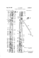
- FIG. 1 is an elevational view showing perforating apparatus including the present invention as it may appear in a well bore;
- FIG. 2 is a schematic view in plan showing the perforating apparatus of FIG. 1 in typical positions for perforating;
- FIG. 3 is a view similar to FIG. 2 but showing the perforating apparatus in typical undesirable positions;
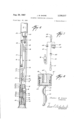
- FIG. 4 is an elevational view in cross-section of one embodiment of the orienting device of the present invention as it will appear in its initial operating position;
- FIG. 5 is a view of the apparatus of FIG. 4 in another operating position
- FIG. 6 is a view of the apparatus of FIG. 4 but illustrating still another of its operating positions
- FIG. 7 is a schematic wiring diagram of suitable electrical circuitry for the apparatus of FIG. 4.
- FIG. 8 is a cross-sectional view of a portion of an alternate embodiment of the present invention.
- FIG. 1 a representative view is shown of a borehole 10 lined with cement Ill to secure a casing 12 extending through productive earth formations 1315.
- a first tubing string 16 depending from conventional wellhead equipment (not shown) at the earths surface, with its lower open end 17 being terminated just above the uppermost productive earth formation 13.
- Second and third tubing strings 18 and 19 are similarly dependently secured at the surface and respectively extended through the casing 12 to a depth above the next lower earth formation 14 and the lower most productive earth formation 15.
- a conventional packer 21 is arranged to seal the space between the interior wall of the casing 12 and the outer walls of the tubing strings 16, 18 and 19 above the uppermost formation 13.
- Another conventional packer 22 is arranged between the formations 13 and 14 to pack-off the annulus around the longer tubing strings 18 and 19; while still another packer 23 may be likewise employed to seal the space between the casing 12 and the longest tubing string 19 between the formations 14 and 15.
- perforating apparatus 24 including a casing-collar locator 25, the orienting and safety device 26 of the present invention and a perforator 27, is dependently suspended from an electrical cable 28 spooled from a winch (not shown) at the earths surface and lowered into the tubing string 16.
- FIG. 1 depicts a so-called retrievable perforator 27 which encloses a plurality of shaped charges (not shOWn) facing closed, lateral ports 29 longitudinally aligned along one side of its carrier, other types of perforators can also be employed so long as their perforating devices are arranged to fire in substantially the same predetermined lateral direction.
- the perforator can be safely actuated to produce a series of longitudinally spaced perforations (not shown) through the casing 12 and cement 11 into the earth formation 13.
- the orienting device 26 of the present invention includes means to position the perforator 27 so it can be safely actuated without damaging an adjacent tubing string such as 18 and 19.
- the orienting device 26 includes an arm 30 (FIGS. 2-6) that is laterally movable by a continued force to an extended position diametrically opposite from the ports 29 (FIG. 1).
- the perforator 27 will be urged toward the opposite side of the casing in its lateral direction of perforation 3 1.
- FIGS. 2 and 3 the various positions that the perforating apparatus 24 can assume are schematically illustrated in FIGS. 2 and 3.
- the perforating apparatus 24 can emerge from the lower open end 17 of the tubing string 16 with the shaped charges 32 facing away from the adjacent tubing strings 18 and 19.
- the arm 30 will be extended between the adjacent strings 18 and 19 against the casing 12 to urge the perforator 27 into the position depicted in full-line in FIG. 2 with its direction of perforation being as shown by arrow 31.
- perforator 27 may, of course, be safely actuated without damaging the adjacent tubing strings 18 and 19.
- the perforating apparatus 24 will come to rest in a position where its direction of perforation 31 does not intersect one of the adjacent tubing strings 18 and 19.
- the perforating apparatus 24 it is quite possible for the perforating apparatus 24 to be urged between both of the adjacent tubing strings 18 and 19 somewhat as illustrated in fullline in FIG. 3.
- the perforator 27 could readily assume a position as shown by the dashed lines in FIG. 3.
- the perforator 27 could possibly be actuated in either of the positions illustrated in FIG. 3 without damaging the adjacent tubing strings 18 and 19, it is considered ,too risky to do so.
- the orienting device 26 of the present invention includes means 35 for disabling the perforator until it is positively facing in a safe direction relative to the adjacent tubing strings.
- the disabling means 35 are arranged whereby the perforator 27 cannot be actuated until the extendible arm 30 has moved outwardly a predetermined distance that can be attained only when the perforating apparatus 24 is either engaged against the casing 12 or is very near thereto. If, for some reason, the extendible arm 30 cannot be moved such a distance, it is very likely that the perforator 27 has assumed a position, such as those in FIG.
- the disabling means 35 of the present invention are made operatively responsive to movement of the extendible arm 30.
- the disabling means 35 can be arranged to disarm the perforator 27 until the arm has reached this predetermined position.
- the perforator 27 should be shifted into a position such as those repre sented in FIG. 3, it will not necessarily remain in such a position. In such an instance, it will be readily ascertainable, for example, by monitoring conventional measuring equipment (not shown) at the surface that an attempt to actuate the perforator 27 was unsuccessful However, upon determining that the perforator 27 was not in fact actuated, repeated reciprocation of the suspension cable 28 will generally suffice to reposition the perforating apparatus 24 to enable the extendible arm 30 to shift the perforator into a safe position. If this is accomplished, the perforator 27 will then be armed once the arm 30 has extended the minimum predetermined strokes previously mentioned. Once the arm 30 has shifted the perforator 27 into a safe position, it can, of course, be actuated upon a second attempt.
- means 36 are provided for selectively retracting the extendible arm 30.
- the retracting means 36 are made responsive to the actuation of the perforator 27.
- the retracting means 36 operate to return the arm 30 to its initial retracted position. With the arm 30 retracted, the perforating apparatus 24 will again be freely suspended from the cable 28. Once the apparatus 24 is freely suspended, it will be appreciated that a pull on the cable 28 will be more likely to maneuver the apparatus around a tubing string to unwrap the cable therefrom. Similarly, should the cable 28 have entered a narrow space between the casing 12 and a bend in a tubing string, as at 19 (FIG. 1), an upward pull on the cable will often slide the upper end of the apparatus 24 along the adjacent surfaces of the tubing and casing to bring the apparatus free of such an obstruction.
- the orienting device 26 includes a tubular housing 37 having an elongated longitudinal slot 38 along one side thereof and closure members 39 and 40 at each end of the housing.
- a tubular sub 41 fluidly sealed by O-rings 42 and secured over the upper end-closure member 39 connects the orienting device 26 to the casing-collar locator 25 and suspension cable 28 (FIG. 1) as well as encloses an electrical switch 43 and other electrical components (not shown).
- the lower end-closure member 40 is fluidly sealed by O-rings 44 and secured within the upper end of a tubular perforator carrier 45.
- Means such as a key or set screw 46 inserted through the carrier 45 into the end-closure member 40, are provided to co-rotatively secure the carrier in a known, fixed radial position relative to the orienting device 26.
- a key or set screw 46 inserted through the carrier 45 into the end-closure member 40, are provided to co-rotatively secure the carrier in a known, fixed radial position relative to the orienting device 26.
- the lateral direction of perforation 31 of the shaped charges 32 (only one shown) within the carrier 45 is fixed diametrically opposite from the elongated slot 38 in the housing 37.
- the orienting arm 30 is comprised of an elongated member 47 having its upper end dependently secured to the outer end of a bifurcated arm 48 of a bell crank 49 and its lower free end 34 curved inwardly and arranged to be pivoted outwardly and upwardly through the elongated housing slot 38.
- the bell crank 49 is pivotally mounted at its fulcrum by a transverse pin 50 passing through the housing 37 on its opposite side from the elongated slot 38.
- the bell crank 49 is arranged with its bifurcated arm 48 extending downwardly at an angle from the pivot pin 50 and its other arm 51 extending upwardly therefrom a short distance into the housing 37.
- an elongated leaf spring member 52 having end portions 53 and 54 tapering slightly from an enlarged central portion 55 is extended longitudinally within the housing 37 parallel to and opposite from the slot 38, with the central portion being confined therein between a transverse pin 56 through the housing and the inside surface of the housing wall 57 opposite the slot.
- the upper end portion 53 of the spring member 52 is flexed inwardly slightly toward the slot 38 and passed through the bifurcated crank arm 48 where its upper end 58 is engaged with the rounded upper end 59 of the shorter crank arm 51.
- a screw 60 through the lower end portion 54 of the spring member 52 has its head confined within a recess 61 in the inner surface of the housing wall 57 to provide an adjustment for the spring member.
- the spring 52 will impose an outwardly directed lateral force 62 on the upper end 59 of the shorter crank arm 51, which force will tend to rotate the orienting arm 30 outwardly in a counterclockwise direction around its pivot 50. It will be appreciated that as the adjustment screw 60 is unthreaded, the lower end portion 54 of the spring 52 will be shifted inwardly. Accordingly, as its lower end portion 54 is moved further under the transverse pin 56, the spring 52 will be flexed still further and, thereby, further increase the lateral force 62 acting outwardly on the crank arm end 59.
- the disabling means 35 include the electrical switch 43 that is appropriately mounted in the tubular sub 41 to align its actuator 63 with a longitudinal bore 64 through the upper end-closure member 39.
- a rod 65 having its upper end slidably received within a conventional stuffing box 66 through the longitudinal bore 64 is threadedly connected at its lower end to a transverse member 67 loosely confined within slots 68 on the opposed sides of the bifurcated crank arm 48.
- a contact pin 69 is slidably received within a blind coaxial bore in the upper end of the actuating rod 65 and normally urged upwardly by a spring (not shown) within the blind bore.
- an adjusting wheel 70 is slidably mounted around a square central portion 71 of the actuating rod 65 above the threads 72 at its lower end.
- the opposite peripheral edges of the adjusting wheel 70 are confined within lateral circumferential grooves 73 on opposite sides of the housing 37.
- releasable latching means 74 To restrain the orienting arm 30 in its retracted position illustrated in FIG. 4, releasable latching means 74 are provided.
- the latching means 74 includes a pivotally mounted latch 75 having a notch 76 on one end 77 thereof that receives the lower end 34 of the orienting arm 30.
- Releasing means such as an electrically initiated explosive squib 78 having a rigid body engaged between the other end 79 of the latch 75 and lower end-closure mem ber 40, are provided to prevent the latch from rotating about its pivot pin 80 until it is desired to release the orienting arm 30.
- an electrical conductor 81 is confined within a sealed conduit 82 that extends between the upper and lower closure members 39 and 40. As will be subsequently described, the conductor 81 is connected to the squib 78 to permit its selective detonation upon command from the surface.
- the contact pin 69 is positioned to depress the switch actuator 63 whenever the extendible arm 30 has reached a predetermined extended position. Then, should the extendible arm 30 move further outwardly, the springloaded contact pin 69 will maintain the actuator 63 depressed but will not be forced further upwardly to possibly damage the switch 43.
- the lower closure member 40 is bored from its opposite ends to provide a pair of longitudinal blind bores 83 and 84.
- the bores are interconnected by a longitudinal passage 85 extending from the blind end of the lower bore 84 to an intersection with a transverse passage 86 that joins the upper portion of the upper bore 83 and is closed at its outer end by a suitable closure member 87.
- the closure member 87 may be arranged to serve as a flow restrictor to regulate the flow rate through the passages 85 and 86.
- a slidable piston member 88 is fluidly sealed within the lower bore 84 by an O-ring 89 and confined therein by a suitable stop member 90 at the bores lower end.
- a second slidable piston member 91 fluidly sealed within the upper bore 83 by an O-ring 92, has a piston rod 93 extending upwardly therefrom and through a stuffing box 94 sealingly fitted into the upper end of the upper bore 83.
- a follower rod 95 couples the upper, exposed end of the piston rod 93 to a clevis 96 that is slidably confined within opposed grooves 97 on opposite sides of the housing 37.
- the spaced arms of the clevis 96 are extended upwardly around the bifurcated crank arm 48 and support the opposite ends of the transverse member 67.
- the interior of the carrier 45 will remain at substantially atmospheric pressure so long as it is not opened, as by the shaped charges 32 puncturing holes therein upon their successful detonation.
- the space 99 (FIG. below the piston will be at a slightly sub-atmospheric pressure. Accordingly, as best seen in FIG. 6, whenever the shaped charges 32 in the sealed carrier 45 are detonated, fluids 100 in the well bore 20 (FIG. 1) will be admitted through the perforated carrier wall to impose their pressure against the underside of the piston member 88 and force it upwardly.
- a flat leaf spring 101 is secured at one end within the housing 37 by a transverse pin 102 and has an inwardly hooked free end 103 engaging the pivotal latch end 77 adjacent to the arm-retaining notch 76.
- the spring is flexed to urge the hooked spring end 103 against the latch end 77'.
- the outer end 59 of the bell crank 49 is preferably shaped in such a manner that the eflective moment arm on which the lateral spring force 62 is applied will increase as the extendible arm 30 swings further outwardly.
- the effective moment arm on which the laterally directed spring force is acting is increased so as to move the extendible arm 30 outwardly with a force 105 (FIG. 5) that is somewhat constant.
- FIG. 7 a wiring diagram is shown of a typical firing circuit that may be employed with the perforating apparatus 24.
- the central conductor 106 of the cable 28 is divided and connected to the common contact 107 of the switch 43 and to a polarity-responsive device, such as a diode 108.
- the opposite end of the diode 108 is connected by conductor 81 to the initiator of the explosive squib 78.
- the explosive squib 7 8 Will be detonated. This, as previously described, releases the orienting arm 30.
- the central conductor 106 will be connected through the switch to another diode 109 oppositely poled to the other diode 108.
- a negative voltage is applied to the central conductor 106, current will flow therefrom by a conductor 110 to a conventional blasting cap 111 for detonating the shaped charges 32 in the usual manner.
- the switch 43 could also be suitably arranged to provide a visual indication at the surface whenever the orienting arm '30 has been sufficiently extended to insure that the perforator 27 is safely positioned.
- FIG. 8 an alternate embodiment is shown of the lowermost portion of an orienting device 26 that is suitably arranged to employ the present invention with a perforator comprised of encapsulated shaped charges (not shown) that are supported from an expendable support 112, such as those shown in Patent Nos. 3,048,101 or 3,100,443, and having the charges facing generally in one lateral direction. It will be recognized that Where such expendable supports are used, the fluids in the well are in contact with the shaped charges.
- the bottom of the lower end-closure member 40' is sealingly enclosed by a frangible cap 113 having a weakened portion 114 adjacent to the open end of the lower bore 84. Then, by extending the detonating cord 115 to within close proximity of the cap 113, upon detonation of the detonating cord, the weakened portion 114. will be fractured to admit fluids in the well into the lower end of the piston bore 84.
- the orienting device 26' is otherwise arranged in the same manner as that shown at 26 in FIGS. 4-6.
- FIGS. 4-6 show the successive positions of the orienting device 26 as the perforating apparatus 24 is manipulated in the manner already described with reference to FIGS. 13.
- the adjustment wheel 70 Prior to placing the apparatus 24 into a tubing string such as 16 (FIG. 1), the adjustment wheel 70 is rotated to bring the actuating rod 65 into a proper spatial relation with the switch actuator 63.
- this spatial relation can be adjusted where the switch 43 will not be closed until the arm 30 has moved to a predetermined extended position.
- the free arm end 34 can so move that it is laterally spaced from the opposite housing wall 57 a distance at least slightly greater than shown in fullline in FIG. 3, it is best not to risk actuating the perforator 27.
- the actuating rod 65 may be readily adjusted to leave the switch 43 open until the arm is unquestionably extended a safe distance.
- FIG. 4 illustrates the orienting device 26 as it will appear until such time that the orienting arm 30 has been released.
- the orienting arm 30 is fully retracted to enable the orienting device 26 to pass freely through a tubing string, such as at 16 in FIG. 1.
- the pivotal latch 75 secures the orienting arm 30 in its retracted position which, in turn, holds both the actuating rod 65 as Well as the piston 91 in their lowermost positions.
- the squib 78 is detonated. This frees the pivotal latch 75 and enables the spring 52 to urge the extendible arm 30 outwardly until it has reached either an adjacent tubing string 18 or 19 or the internal Wall of the casing 12.
- the linkage interconnecting it to the piston rod 93 pulls the piston 91 upwardly and displaces hydraulic fluid 98 from the piston bore 83 to shift the other piston 88 downwardly into the position shown in FIG. 5.
- the arm 30 will, of course, swing outwardly a sufficient distance to close the switch 43. Nevertheless, so long as the orienting arm 30 has not moved outwardly a suflicient distance calculated to insure that the perforator 27 is not in an undesired position, as in FIG. 3, the actuating rod 65 will not have shifted upwardly a suflicient distance to actuate the switch 43. Accordingly, as previously explained, so long as the switch 43 remains open, the firing circuit to the shaped charges 32 remains open thereby preventing their detonation.
- the contact pin 69 will depress the switch actuator 63 to close the switch 43.
- the perforator 27 may be safely actuated.
- the sealed carrier 45 will be .punctured by the resultant perforating jets to admit fluids in the well bore.
- the piston 88 will be bottomed in the bore 84 and, by operation of the other piston 91 and interconnecting link age, retract the arm 30.
- the arm 30 has returned sufficiently to allow the latch spring 101 to hook the nose 77 of the pivotal latch 75, the free end 34 of the arm will be secured in the position seen in FIG. 6. Then, With the arm 30 secured, the perforating apparatus 24 is free of any lateral restraint to facilitate its successful return into the lower, open tubing end 17 and safe recovery.
- the alternate embodiment 26 depicted in FIG. 8 will, of course, operate in the same manner.
- the detonation of the extension of the detonating cord will fracture the weakened portion 114 of the frangible cap 113 to admit fluids from the well into the lower portion of the piston bore 84.
- the orienting device 26' will function as already described.
- the present invention has provided means for positively orienting a perforator having a selected lateral direction of perforation in such a manner that the perforator will be positively directed away from an adjacent tubing string. Moreover, the perforator will be positively disabled until such time that it faces in a safe direction. Then, once the perforator is actuated, the present invention provides means for subsequently retracting the orienting arm to facilitate the withdrawal of the perforating apparatus.
- perforating apparatus adapted for pas sage through the shorter of the pipe strings comprising: perforating means having a selected lateral direction of perforation; orienting means on said perforating apparatus and laterally movable with respect thereto between a normal retracted position permitting passage of said perforating apparatus through the shorter string and an extended position against an opposing surface in a well bore diametrically opposite said direction of perforation; means for moving said orienting means to said extended position; and means on said perforating apparatus for returning said orienting means to said retracted position.
- perforating apparatus adapted for passage through the shorter of the pipe strings comprising: perforating means having a selected lateral direction of perforation; orienting means movably connected to said perforating apparatus and laterally movable with respect thereto between a normal retracted position permitting passage of said perforating apparatus through the shorter string and an extended position against an opposing surface in a well bore diametrically opposite said direction of perforation; means for moving said orienting means to said extended position to urge said perforating apparatus in said direction of perforation; and means responsive to actuation of said perforating means for returning said orienting means to said retracted position.
- perforating apparatus adapted for passage through the shorter of the pipe strings comprising: electrically-detonated perforating means having a selected lateral direction of perforation; orienting means movably connected to said perforating means and laterally movable with respect thereto between a normal retracted position permitting passage of said perforating apparatus through the shorter string and an extended position diametrically opposite said direction of perforation; means for moving said orienting means to said extended position against an opposing surface in a well bore to urge said perforating apparatus in said direction of perforation; switch means for disabling said perforating means until said orienting arm has moved to said extended position; and means responsive to actuation of said perforating means for returning said orienting means to said retracted position.
- perforating apparatus adapted for passage through the shorter of the pipe strings comprising: a perforator including perforating means having a selected lateral direction of perforation; an orienting arm movably connected to said perforator and laterally movable with respect thereto between a normal retracted position permitting passage of said perforating apparatus through the shorter string and an extended position diametrically opposite said direction of perforation; means for moving said orienting arm to said extended position; and means for returning said orienting arm to said retracted position including a portion of said apparatus having a bore therein, a piston slidably disposed in said bore and fluidly sealed therein to define a sealed space in said bore on one side of said piston, means connecting said piston to said orienting arm, and means responsive to actuation of said perforator for admitting well pressure into said bore on the other side of said piston to move said piston and retract said orienting arm.
- perforating apparatus adapted for passage through the shorter of the pipe strings comprising: a perforator including perforating means having a selected lateral direction of perforation; an orienting arm movably connected to said perforator and laterally movable with respect thereto between a normal retracted position permitting passage of said perforating apparatus through the shorter string and an extended position diametrically opposite said direction of perforation; means for moving said orienting arm to said extended position; and means for returning said orienting arm to said retracted position including a portion of said apparatus having a bore therein, a piston slidably disposed in said bore and fluidly sealed therein to define a sealed space in said bore on one side of said piston, means connecting said piston to said orienting arm, and means normally preventing communication of well bore pressure into said bore and opened by detonation .of said perforating means to admit such pressure into said bore on the other side of
- perforating apparatus adapted for passage through the shorter of the pipe strings comprising: a perforator including electrically-detonated perforating means having a selected lateral direction of perforation;
- an orienting arm movably connected to said perforator and laterally movable with respect thereto between a normal retracted position permitting passage of said perforating apparatus through the shorter string and an extended position diametrically opposite said direction of perforation; means for moving said orienting arm to said extended position; switch means for disabling said perforating means until said orienting arm has moved to said extended position; and means for returning said orienting arm to said retracted position including a portion of said apparatus having a bore therein, a piston slidably disposed in said bore and fluidly sealed therein to define a sealed space in said bore on one side of said piston, means connecting said piston to said orienting arm, and means normally preventing communication of well bore pressure into said bore and opened by detonation of said perforating means to admit such pressure into said bore on the other side of said piston to move said piston and retract said orienting arm,
- perforating apparatus adapted for passage through the shorter of the pipe strings comprising: a body having a bore therein; encapsulated shaped charge means having a selected lateral direction of perforation connected to said body; orienting means movably mounted on said body and laterally movable between a retracted position permitting passage of said perforating apparatus through the shorter string and an extended position against an opposing surface in the well bore diametrically opposite said direction .of perforation; means for moving said orienting means to said extended position; and means for returning said orienting means to said retracted position including a slidable piston fluidly sealed in said bore and defining a sealed space therein on one side of said piston, means connecting said piston to said orienting means, passage means between said bore on the other side of said piston and the exterior of said body, means releasably sealing said passage means, and explosive means between said shaped charge means and passage-
- perforating apparatus adapted for passage through the shorter of the pipe strings comprising: a body having a bore therein; encapsulated shaped charge means having a selected lateral direction of perforation connected to said body; an orienting arm pivotally mounted to said body and having a free end arranged to move laterally between a retracted position adjacent to said body and an extended position against an opposing surface in the well bore diametrically opposite said direction of perforation; spring means urging said orienting arm toward said extended position; means releasably holding said orienting arm in said retracted position and selectively operable to release said orienting arm; and means for returning said orienting arm to said retracted position including a slidable piston fluidly sealed in said bore and defining a sealed space therein on one side of said piston, means connecting said piston to said orienting arm, passage means between said bore on the other side of said piston and the
- perforating apparatus adapted for passage through the shorter of the pipe strings comprising: a body having abore therein; encapsulated shaped charge means having a selected lateral direction of perforation connected to said body; an orienting arm pivotally mounted to said body and having a free end arranged to move laterally between a retracted position adjacent to said body and an extended position against an opposing surface in the well bore diametrically opposite said direction of perforation; spring means urging said orienting arm toward said extended position; means releasably holding said orienting arm in said retracted position and selectively operable to release said orienting arm; means for returning said orienting arm to said retracted position including a first slidable piston fluidly sealed in said bore and defining a sealed space therein on one side of said piston, means connecting said piston to said orienting arm, passage means between said bore on the other side of said piston and the
- perforating apparatus adapted for passage through the shorter of the pipe strings comprising: a body having a bore therein; electrically-detonated encapsulated shaped charge means having a selected lateral direction of perforation connected to said body; an orienting arm pivotally mounted to said body and having a free end arranged to move laterally between a retracted position adjacent to said body and an extended position against an opposing surface in the well bore diametrically opposite said direction of perforation; spring means urging said orienting arm toward said extended position; means releasably holding said orienting arm in said retracted position and selectively operable to release said orienting arm; switch means for disabling said shaped charge means until said orienting arm has moved to said extended position; means for returning said orienting arm to said retracted position including a first slidable piston fluidly sealed in said bore and defining a sealed space therein on
- perforating apparatus adapted for passage through the shorter of the pipe strings comprising: a sealed carrier; shaped charge means in said carrier and having a selected lateral direction of perforation intersecting a wall of said carrier; orienting means movably mounted on said perforating apparatus and laterally movable with respect thereto between a normal retracted position permitting passage of said perforating apparatus through the shorter string and an extended position against an opposing surface in a well bore diametrically opposite said direction of perforation; means for moving said orienting means to said extended position to urge said perforating apparatus in said direction of perforation; and hydraulic means responsive to entrance of fluid into said carrier upon perforation of said carrier wall by said shaped charge means for returning said orienting means to said retracted position.
- perforating apparatus adapted for passage through the shorter of the pipe strings comprising: a sealed carrier; shaped charge means in said carrier and having a selected lateral direction of perforation intersecting a wall of said carrier; a body having a bore therein and connected to said carrier; orienting means movably mounted on said body and laterally movable between a retracted position permitting passage of said perforating apparatus through the shorter string and an extended position against an opposing surface in the well bore diametrically opposite said direction of perforation; means for moving said orienting means to said extended position; and means for returning said orienting means to said retracted position including a slidable piston fluidly sealed in said bore and defining a sealed space therein on one side of said piston, means connecting said piston to said orienting means, and passage means between said bore on the other side of said piston and the interior of said carrier.
- perforating apparatus adapted for passage through the shorter of the pipe strings comprising: a sealed carrier; shaped charge means in said carrier and having a selected lateral direction of perforation intersecting a wall of said carrier; a body having a bore therein and connected to said carrier; an orienting arm pivotally mounted to said body and having a free end arranged to move laterally between a retracted position adjacent to said body and an extended position against an opposing surface in the well bore diametrically opposite said direction of perforation; spring means urging said orienting arm toward said extended position; means releasably holding said orienting arm in said retracted osition and selectively operable to release said orienting arm; and means for returning said orienting arm to said retracted position including a slidable piston fluidly sealed in said bore and defining a sealed space therein on one side of said piston, means connecting said piston to said orient
- perforating apparatus adapted for passage through the shorter of the pipe strings comprising: a sealed carrier, shaped charge means in said carrier and having a selected lateral direction of perforation intersecting a wall of said carrier; a body having a bore therein and connected to said carrier; an orienting arm pivotally mounted to said body and having a free end arranged to move laterally between a retracted position adjacent to said body and an extended position against an opposing surface in the well bore diametrically opposite said direction of perforation; spring means urging said orienting arm toward said extended position; means releasably holding said orienting arm in said retracted position and selectively operable to release said orienting arm; means for returning said orienting arm to said retracted position including a first slidable piston fluidly sealed in said bore and defining a sealed space therein on one side of said piston, means connecting said piston to said orienting arm,
- perforating apparatus adapted for passage through the shorter of the pipe strings comprising: a sealed carrier; electrically-detonated shaped charge means in said carrier and having a selected lateral direction of perforation intersecting a wall of said carrier; a body having a bore therein and connected to said carrier; an orienting arm pivotally mounted to said body and having a free end arranged to move laterally between a retracted position adjacent to said body and an extended position against an opposing surface in the well bore diametrically opposite said direction of perforation; spring means urging said orienting arm toward said extended position; means releasably holding said orienting arm in said retracted position and selectively operable to release said orienting arm; switch means for disabling said shaped charge means until said orienting arm has moved to said extended position; means for returning said orienting arm to said retracted position including a first slidable piston fluidly
- apparatus adapted for connection to a well tool comprising: a body having a longi tudinal opening along one side thereof; an arm member pivotally mounted at an intermediate point to said body and having a free end portion arranged relative to said opening for movement therethrough between a retracted position within said body and an extended position exterior thereof; spring means between the other end portion of said arm member and said body for urging said free arm portion toward said extended position; means holding said arm member in said retracted position including a rigid member detonatable to fracture said rigid member and release said arm member for movement to said extended position; switch means on said body; switchactuating means between said switch means and arm member and responsive to movement of said arm member for operating said switch means in one of said arm member positions; arm-retracting means including a slidable piston fluidly sealed in said body, means connecting said piston to saidarm member, means fluidly sealing said consaid piston;
- 16 necting means to define an enclosed space between said piston and arm member, and passage means adapted for communicating a pressure diflerential across said piston; and latching means for securing said arm member upon its return to said retracted position.
- apparatus adapted for connection to a well tool comprising: a body having a longitudinal opening along one side thereof; an arm member pivotally mounted at an intermediate point to said body and having a free end portion arranged relative to said opening for movement therethrough between a retracted position within said body and an extended position exterior thereof; spring means between the other end portion of said arm member and said body for urging said free arm portion toward said extended position; means holding said arm member in said retracted position including a latch member pivotally mounted on said body and movable between an arm-engaging position and an arm-releasing position, a rigid member between said pivotal latch and body holding said latch in said arm-engaging position, and explosive means adjacent to said rigid member selectively detonatable to fracture said rigid member and enable said pivotal latch to move to said arm-releasing position; switch means on said body; switch-actuating means between said switch means and arm member and responsive to movement of said arm member for operating said switch means in one of said arm member positions; arm-retracting means including a latch member pivotally mounted at an intermediate point to
Landscapes
- Engineering & Computer Science (AREA)
- Life Sciences & Earth Sciences (AREA)
- Geology (AREA)
- Mining & Mineral Resources (AREA)
- Physics & Mathematics (AREA)
- Environmental & Geological Engineering (AREA)
- Fluid Mechanics (AREA)
- General Life Sciences & Earth Sciences (AREA)
- Geochemistry & Mineralogy (AREA)
- Mechanical Engineering (AREA)
- Earth Drilling (AREA)
Description
1967 J. B. SHORE 3,338,317
ORIENTED PERFORATING APPARATUS Filed Sept. 22, 1965 3 Sheets-Sheet l James B. 5/70/6 INVENTOR ATTORNEY Aug. 29, 1967 J. B. SHORE 3,338,317
ORIENTED PERFORATING APPARATUS Filed Sept. 22, 1965 it 4o 3 Sheets-Sheet 2 (/c zmes .5 Shore INVENTOR.
// Aria/FIVE Patented Aug. 29, 1967 3,338,317 ORIENTED PERFORATING APPARATUS James B. Shore, Friendswood, Tex., assignor to Schlumberger Technology Corporation, Houston, Tex., a corporation of Texas Filed Sept. 22, 1965, Ser. No. 489,114 17 Claims. (Cl. 1754.51)
This invention relates to preforating apparatus for use in multiple-completion well bores; and, more particularly, to new and improved means for orienting such perforating apparatus and preventing its premature actuation until it has been properly oriented relative to adjacent tubing strings and for facilitating the retrieval of the expended apparatus.
In one technique of completing oil wells having a plurality of spaced productive earth formations, the well is cased as required and individual tubing strings extended to a depth generally slightly above each of the several formation intervals. To isolate these productive formations from one another, means, such as conventional packers, are employed to pack-01f the well bore between the casing and tubing strings near the upper limit of each of the productive formations. Thus, once the tubing strings and these packers arein position, the lower portion of the well bore is divided into a series of vertically spaced, isolated intervals with only a single tubing string communicating with each productive interval and, except for the lowermost interval, through which one or more of the other tubing strings extend to the lower intervals.
Once this part of the completion operation is finished, the casing must, of course, be perforated adjacent each productive interval to obtain communication with the adjacent formations therearound. To accomplish this, perforating apparatus, such as shaped charges mounted on expendable supports or confined within retrievable enclosed carriers, is successively lowered through each of the tubing strings in turn. Upon reaching the productive interval in which that particular tubing string terminates, the apparatus is lowered below the lower open end of the string into the isolated interval and then actuated.
It will be appreciated, however, that, in all but the lowermost of these productive intervals, the perforating apparatus must also be laterally directed to avoid perforating the other tubing strings passing through that interval to other intervals therebelow. Accordingly, it has been necessary heretofore to employ such arrangements as pre-positioned guides on the tubing strings that cooperatively engage and orient the perforating apparatus to direct its axis of perforation away from the adjacent tubing strings passing through that productive interval.
Typical of such orienting arrangements i that shown in the Lebourg Patent No. 3,168,141 wherein tubular subs having an enlarged, eccentric or offset portion are coupled to the lower end of all but the longest string before the tubing is placed in the well. To ensure that the offset portions of these locating subs are correctly aligned with respect to the adjacent strings, the tubing strings must be firmly secured to one another and lowered as a group into the well. Then, a perforator having an extendible orienting arm is successively positioned in each tubing string and manipulated until the extendible arm enters the olfset portion of the locating sub for that string to direct the perforator away from the adjacent strings. Although such arrangements as that shown in the Lebourg patent have been successfully employed, it will be recognized that it is not always desirable or possible to pre-position these locating subs. It is also particularly time-consuming and generally more expensive to run two or more pipe strings into a well simultaneusly. Moreover, once such locating subs are installed, they can be somewhat of an obstacle to passage of other tools as well as of no utility should it later be desired to perforate the well at a substantially different depth.
Accordingly, it is an object of the present invention to provide new and improved apparatus for orienting a perforator in multiple-completion wells without such prepositioned guides that positively prevents premature actuation of the perforator until it is directed away from adjacent tubing strings as well as subsequently facilitates the withdrawal of the perforating apparatus.
This and other objects of the present invention are accomplished by connecting to a perforator having a selected lateral direction of perforation a normally-retracted orienting arm having a wall-engaging portion that is extendible to a position substantially diametrically opposite the direction of perforation-Means are provided for selectively extending the orienting arm with sufficient force after the perforator has emerged from the open end of a pipe string to shift the perforator laterally in the direction it is to perforate. Disabling means are provided to deactivate the perforators perforating devices until the orienting arm has extended a minimum distance representative of a substantial proportion of the well bore diameter at the depth of perforation. Thus, by rendering the perforating devices inoperative until the orienting arm has been extended at least this minimum distance, the perforator cannot be actuated until its direction of perforation is faced away from adjacent tubing strings. Means are further provided for subsequently retracting the orienting arm once the perforator has been fired to facilitate withdrawal of the perforating apparatus.
The novel features of the present invention are set forth with particularity in the appended claims. The present invention, both as to its organization and manner of operation together with further objects and advantages thereof, may best be understood by way of illustration and example of certain embodiments when taken in conjunction with the accompanying drawings, in which:
FIG. 1 is an elevational view showing perforating apparatus including the present invention as it may appear in a well bore;
FIG. 2 is a schematic view in plan showing the perforating apparatus of FIG. 1 in typical positions for perforating;
FIG. 3 is a view similar to FIG. 2 but showing the perforating apparatus in typical undesirable positions;
FIG. 4 is an elevational view in cross-section of one embodiment of the orienting device of the present invention as it will appear in its initial operating position;
FIG. 5 is a view of the apparatus of FIG. 4 in another operating position;
FIG. 6 is a view of the apparatus of FIG. 4 but illustrating still another of its operating positions;
FIG. 7 is a schematic wiring diagram of suitable electrical circuitry for the apparatus of FIG. 4; and
FIG. 8 is a cross-sectional view of a portion of an alternate embodiment of the present invention.
Turning now to FIG. 1, a representative view is shown of a borehole 10 lined with cement Ill to secure a casing 12 extending through productive earth formations 1315. In the casing 12 is a first tubing string 16 depending from conventional wellhead equipment (not shown) at the earths surface, with its lower open end 17 being terminated just above the uppermost productive earth formation 13. Second and third tubing strings 18 and 19 are similarly dependently secured at the surface and respectively extended through the casing 12 to a depth above the next lower earth formation 14 and the lower most productive earth formation 15. To isolate the productive formations 1315 from the upper portion of the well bore 20, a conventional packer 21 is arranged to seal the space between the interior wall of the casing 12 and the outer walls of the tubing strings 16, 18 and 19 above the uppermost formation 13. Another conventional packer 22 is arranged between the formations 13 and 14 to pack-off the annulus around the longer tubing strings 18 and 19; while still another packer 23 may be likewise employed to seal the space between the casing 12 and the longest tubing string 19 between the formations 14 and 15.
To perforate the casing 12 opposite the uppermost earth formation 13, perforating apparatus 24 including a casing-collar locator 25, the orienting and safety device 26 of the present invention and a perforator 27, is dependently suspended from an electrical cable 28 spooled from a winch (not shown) at the earths surface and lowered into the tubing string 16. It will be understood, of course, that although FIG. 1 depicts a so-called retrievable perforator 27 which encloses a plurality of shaped charges (not shOWn) facing closed, lateral ports 29 longitudinally aligned along one side of its carrier, other types of perforators can also be employed so long as their perforating devices are arranged to fire in substantially the same predetermined lateral direction. Thus, by directing the lateral direction of perforation of the perforator 27 away from both of the adjacent strings 18 and 19, the perforator can be safely actuated to produce a series of longitudinally spaced perforations (not shown) through the casing 12 and cement 11 into the earth formation 13.
After the perforating apparatus 24 has emerged from the lower open end 17 of the tubing string 16, it is, of course, substantially free to rotate or be shifted laterally in any direction with little or no restraint or guidance from the cable 28. Accordingly, as will be subsequently explained in detail, the orienting device 26 of the present invention includes means to position the perforator 27 so it can be safely actuated without damaging an adjacent tubing string such as 18 and 19. To accomplish this, the orienting device 26 includes an arm 30 (FIGS. 2-6) that is laterally movable by a continued force to an extended position diametrically opposite from the ports 29 (FIG. 1). Inasmuch as the perforating apparatus 24 is freely suspended, it will be appreciated that when the arm 30 is forced against one side of the casing 12, the perforator 27 will be urged toward the opposite side of the casing in its lateral direction of perforation 3 1.
' It will be recognized that there are a great number of directions in which the perforator 27 can face once it is lowered into an isolated zone. Thus, as a preliminary to a detailed description of the invention, the various positions that the perforating apparatus 24 can assume are schematically illustrated in FIGS. 2 and 3. For example, the perforating apparatus 24 can emerge from the lower open end 17 of the tubing string 16 with the shaped charges 32 facing away from the adjacent tubing strings 18 and 19. In this event, the arm 30 will be extended between the adjacent strings 18 and 19 against the casing 12 to urge the perforator 27 into the position depicted in full-line in FIG. 2 with its direction of perforation being as shown by arrow 31.
On the other hand, should the shaped charges 32 be initially facing one of the adjacent tubing strings 18 or 19, as the arm 30 is extended into the position shown in the dashed lines in FIG. 2, the perforating apparatus 24 will be urged against that tubing string, as for example, 18, When the perforator 27 reaches a position as represented by the dashed lines in FIG. 2, the continued force of the orienting arm 30 against the casing 12 will deflect the perforating apparatus 24 somewhat tangentially away from the tubing string 18 and in the direction shown by arrow 33. It will be realized that should the arm 38 initially engage one of the tubing strings 18 and 19, the continued force thereon will be effective to cause it to slide to one side or the other, of that tubing string. Once the perforating apparatus 24 is against the casing 12, the
perforator 27 may, of course, be safely actuated without damaging the adjacent tubing strings 18 and 19.
It will be recognized, however, that it is not always certain that the perforating apparatus 24 will come to rest in a position where its direction of perforation 31 does not intersect one of the adjacent tubing strings 18 and 19. For example, it is quite possible for the perforating apparatus 24 to be urged between both of the adjacent tubing strings 18 and 19 somewhat as illustrated in fullline in FIG. 3. Similarly, should the outer end 34 of the arm 30 become engaged with an irregularity on the wall of the casing 12, the perforator 27 could readily assume a position as shown by the dashed lines in FIG. 3. Although the perforator 27 could possibly be actuated in either of the positions illustrated in FIG. 3 without damaging the adjacent tubing strings 18 and 19, it is considered ,too risky to do so.
Accordingly, to be certain that actuation of the perforator 27 will neither damage nor puncture the adjacent strings 18 and 19, the orienting device 26 of the present invention includes means 35 for disabling the perforator until it is positively facing in a safe direction relative to the adjacent tubing strings. To accomplish this, the disabling means 35 are arranged whereby the perforator 27 cannot be actuated until the extendible arm 30 has moved outwardly a predetermined distance that can be attained only when the perforating apparatus 24 is either engaged against the casing 12 or is very near thereto. If, for some reason, the extendible arm 30 cannot be moved such a distance, it is very likely that the perforator 27 has assumed a position, such as those in FIG. 3, where its actuation might well damage at least one of the adjacent tubing strings 18 or 19. Thus, as will be subsequently described in greater detail, the disabling means 35 of the present invention are made operatively responsive to movement of the extendible arm 30. By selecting a minimum stroke through which the arm 30 must move in accordance with the geometrical and dimensional parameters of a particular well bore to avoid an adjacent tubing string, the disabling means 35 can be arranged to disarm the perforator 27 until the arm has reached this predetermined position.
It will be appreciated, of course, that should the perforator 27 be shifted into a position such as those repre sented in FIG. 3, it will not necessarily remain in such a position. In such an instance, it will be readily ascertainable, for example, by monitoring conventional measuring equipment (not shown) at the surface that an attempt to actuate the perforator 27 was unsuccessful However, upon determining that the perforator 27 was not in fact actuated, repeated reciprocation of the suspension cable 28 will generally suffice to reposition the perforating apparatus 24 to enable the extendible arm 30 to shift the perforator into a safe position. If this is accomplished, the perforator 27 will then be armed once the arm 30 has extended the minimum predetermined strokes previously mentioned. Once the arm 30 has shifted the perforator 27 into a safe position, it can, of course, be actuated upon a second attempt.
After the perforator 27 has been actuated, it is necessary, of course, to retrieve the perforating apparatus 24 by pulling it back through the open end 17 of the tubing string 16 from which it had previously emerged. This may, however, prove to be a significant feat. For example, as best seen in FIG. 1, it is not at all uncommon for one or more of the tubing strings, such as at 19, to be deviated or cork screwed down through the casing 12 in a particularly long isolated interval as between the widely spaced packers 22 and 23. Thus, as the suspension cable 28 is being manipulated to bring the perforator 27 into a safe firing position at a selected depth, it is quite possible for the cable to become wrapped at least par- 1 tially around the adjacent tubing string 19. Should this or similar entanglements occur, it will be appreciated that if the extendible arm 30 were to continually urge the perforating apparatus 24 against the casing '12 below the entanglement, the chances of freeing the cable 28 would be substantially lessened.
Accordingly, as will subsequently be described in greater detail, means 36 are provided for selectively retracting the extendible arm 30. To eliminate the necessity of arranging special electrical circuitry or providing a separate conductor in the cable 28, the retracting means 36 are made responsive to the actuation of the perforator 27. Thus, whenever the perforator 27 is actuated,
the retracting means 36 operate to return the arm 30 to its initial retracted position. With the arm 30 retracted, the perforating apparatus 24 will again be freely suspended from the cable 28. Once the apparatus 24 is freely suspended, it will be appreciated that a pull on the cable 28 will be more likely to maneuver the apparatus around a tubing string to unwrap the cable therefrom. Similarly, should the cable 28 have entered a narrow space between the casing 12 and a bend in a tubing string, as at 19 (FIG. 1), an upward pull on the cable will often slide the upper end of the apparatus 24 along the adjacent surfaces of the tubing and casing to bring the apparatus free of such an obstruction.
Turning now to FIG. 4, a preferred embodiment is shown of the orienting device 26 of the present invention having the above-described means 35 and 36. The orienting device 26 includes a tubular housing 37 having an elongated longitudinal slot 38 along one side thereof and closure members 39 and 40 at each end of the housing. A tubular sub 41 fluidly sealed by O-rings 42 and secured over the upper end-closure member 39 connects the orienting device 26 to the casing-collar locator 25 and suspension cable 28 (FIG. 1) as well as encloses an electrical switch 43 and other electrical components (not shown). Similarly, the lower end-closure member 40 is fluidly sealed by O-rings 44 and secured within the upper end of a tubular perforator carrier 45. Means, such as a key or set screw 46 inserted through the carrier 45 into the end-closure member 40, are provided to co-rotatively secure the carrier in a known, fixed radial position relative to the orienting device 26. Thus, as best seen in FIG. 4, the lateral direction of perforation 31 of the shaped charges 32 (only one shown) within the carrier 45 is fixed diametrically opposite from the elongated slot 38 in the housing 37.
The orienting arm 30 is comprised of an elongated member 47 having its upper end dependently secured to the outer end of a bifurcated arm 48 of a bell crank 49 and its lower free end 34 curved inwardly and arranged to be pivoted outwardly and upwardly through the elongated housing slot 38. The bell crank 49 is pivotally mounted at its fulcrum by a transverse pin 50 passing through the housing 37 on its opposite side from the elongated slot 38. To reduce the orienting device 26 to a minimum diameter commensurate with the internal diameters of smaller tubing strings, the bell crank 49 is arranged with its bifurcated arm 48 extending downwardly at an angle from the pivot pin 50 and its other arm 51 extending upwardly therefrom a short distance into the housing 37.
T o urge the arm 30 outwardly, an elongated leaf spring member 52 having end portions 53 and 54 tapering slightly from an enlarged central portion 55 is extended longitudinally within the housing 37 parallel to and opposite from the slot 38, with the central portion being confined therein between a transverse pin 56 through the housing and the inside surface of the housing wall 57 opposite the slot. The upper end portion 53 of the spring member 52 is flexed inwardly slightly toward the slot 38 and passed through the bifurcated crank arm 48 where its upper end 58 is engaged with the rounded upper end 59 of the shorter crank arm 51. A screw 60 through the lower end portion 54 of the spring member 52 has its head confined within a recess 61 in the inner surface of the housing wall 57 to provide an adjustment for the spring member.
Thus, when the orienting arm 30 is in the retracted position depicted in FIG. 4, the spring 52 will impose an outwardly directed lateral force 62 on the upper end 59 of the shorter crank arm 51, which force will tend to rotate the orienting arm 30 outwardly in a counterclockwise direction around its pivot 50. It will be appreciated that as the adjustment screw 60 is unthreaded, the lower end portion 54 of the spring 52 will be shifted inwardly. Accordingly, as its lower end portion 54 is moved further under the transverse pin 56, the spring 52 will be flexed still further and, thereby, further increase the lateral force 62 acting outwardly on the crank arm end 59.
The disabling means 35 include the electrical switch 43 that is appropriately mounted in the tubular sub 41 to align its actuator 63 with a longitudinal bore 64 through the upper end-closure member 39. A rod 65 having its upper end slidably received within a conventional stuffing box 66 through the longitudinal bore 64 is threadedly connected at its lower end to a transverse member 67 loosely confined within slots 68 on the opposed sides of the bifurcated crank arm 48. A contact pin 69 is slidably received within a blind coaxial bore in the upper end of the actuating rod 65 and normally urged upwardly by a spring (not shown) within the blind bore. To vary the spacing between the switch actuator 63 and upper end of the contact pin 69, an adjusting wheel 70 is slidably mounted around a square central portion 71 of the actuating rod 65 above the threads 72 at its lower end. The opposite peripheral edges of the adjusting wheel 70 are confined within lateral circumferential grooves 73 on opposite sides of the housing 37. Thus, by rotating the adjusting wheel 70 in the appropriate direction, the actuating rod 65 may be-shifted either upwardly or downwardly through the wheel to position the contact pin 69 as desired in relation to the switch actuator 63.
To restrain the orienting arm 30 in its retracted position illustrated in FIG. 4, releasable latching means 74 are provided. The latching means 74 includes a pivotally mounted latch 75 having a notch 76 on one end 77 thereof that receives the lower end 34 of the orienting arm 30. Releasing means, such as an electrically initiated explosive squib 78 having a rigid body engaged between the other end 79 of the latch 75 and lower end-closure mem ber 40, are provided to prevent the latch from rotating about its pivot pin 80 until it is desired to release the orienting arm 30. To detonate the squib 78, an electrical conductor 81 is confined within a sealed conduit 82 that extends between the upper and lower closure members 39 and 40. As will be subsequently described, the conductor 81 is connected to the squib 78 to permit its selective detonation upon command from the surface.
Thus, as best seen in FIG. 4, so long as the latch 75 is prevented from rotating by the squib 78, the lower end 34 of the extendible arm 30 will be confined within the latch notch 76 and cannot be extended. With the arm 30 in this position, the actuating rod 65 is adjusted so that the contact pin 69 does not engage the switch actuator 63.
To release the extendible arm 30, it is only necessary to detonate the squib 78. As best seen in FIG. 5, upon detonation of the squib 78, its upper portion is disintegrated thereby freeing the pivotal latch 75 for clockwise rotation. Once the latch 75 is freed, the laterally directed force 62 from spring 52 against the outer rounded end 59 of the bell crank 49 will rotate the orienting arm 30 in a counterclockwise direction around its pivot 50. As the free arm end 34 swings upwardly and outwardly, the transverse member 67 will shift the actuating rod 65 longitudinally upwardly. It will be realized, of course, that the loose fit of the transverse member 67 within the opposed slots 68 permits the actuating rod 65 to move smoothly in a longitudinal direction as the bifurcated crank arm 48 pivots. By properly adjusting the wheel 70,
the contact pin 69 is positioned to depress the switch actuator 63 whenever the extendible arm 30 has reached a predetermined extended position. Then, should the extendible arm 30 move further outwardly, the springloaded contact pin 69 will maintain the actuator 63 depressed but will not be forced further upwardly to possibly damage the switch 43.
Turning now to the selectively operable means 36 for retracting the extendible arm 30. As best seen in FIG. 4, the lower closure member 40 is bored from its opposite ends to provide a pair of longitudinal blind bores 83 and 84. The bores are interconnected by a longitudinal passage 85 extending from the blind end of the lower bore 84 to an intersection with a transverse passage 86 that joins the upper portion of the upper bore 83 and is closed at its outer end by a suitable closure member 87. If desired, the closure member 87 may be arranged to serve as a flow restrictor to regulate the flow rate through the passages 85 and 86. A slidable piston member 88 is fluidly sealed within the lower bore 84 by an O-ring 89 and confined therein by a suitable stop member 90 at the bores lower end. A second slidable piston member 91, fluidly sealed within the upper bore 83 by an O-ring 92, has a piston rod 93 extending upwardly therefrom and through a stuffing box 94 sealingly fitted into the upper end of the upper bore 83.
A follower rod 95 couples the upper, exposed end of the piston rod 93 to a clevis 96 that is slidably confined within opposed grooves 97 on opposite sides of the housing 37. The spaced arms of the clevis 96 are extended upwardly around the bifurcated crank arm 48 and support the opposite ends of the transverse member 67. Thus, it will be appreciated that whenever the bell crank 49 pivots to swing the extendible arm 30 outwardly and draw the clevis 96 upwardly, the follower rod 95 and piston rod 93 will pull the piston 91 upwardly.
Accordingly, when the longitudinal bores 83 and 84 and interconnecting passages 85 and 86 are filled with a suitable hydraulic fluid 98, it will be appreciated that as the piston 91 is pulled upwardly, fluid will be displaced from the upper bore 83 through the interconnecting passages and into the lower bore 84. As the hydraulic fluid 98 is displaced into the lower bore 84, the lower piston 88 will be forced downwardly a distance that is proportionately related to the lateral distance which the extendible arm 30 swings outwardly. Conversely, it will also be realized that by forcing the lower piston 88 upwardly to its initial position, the upper piston 91 will be returned to its initial position as the hydraulic fluid 98 is displaced back into the upper bore 83.
It will be appreciated that the interior of the carrier 45 will remain at substantially atmospheric pressure so long as it is not opened, as by the shaped charges 32 puncturing holes therein upon their successful detonation. Moreover, as the piston member 91 is drawn upwardly by the extension of the arm 30, the space 99 (FIG. below the piston will be at a slightly sub-atmospheric pressure. Accordingly, as best seen in FIG. 6, whenever the shaped charges 32 in the sealed carrier 45 are detonated, fluids 100 in the well bore 20 (FIG. 1) will be admitted through the perforated carrier wall to impose their pressure against the underside of the piston member 88 and force it upwardly.
As the fluids 100 in the well bore 20 force the lower piston 88 upwardly, the hydraulic fluid 98 will be displaced from the lower piston bore 84 and back into the upper piston bore 83 by way of the interconnecting passages 85 and 86 to force the upper piston 91 downwardly to its initial position. As the upper piston 91 moves downwardly, the piston rod 93 will, of course, return the follower rod 95 and clevis 96 to their initial positions. As the clevis 96 moves downwardly, the transverse member 67 will restore the actuating rod 65 as well as the bell crank 49 to their original positions. It will be recognized, of course, that the lower piston 88 and hydraulic fluid 98 could be omitted and allow the well fluids to enter the upper piston bore 83 instead. This is not desirable, however, inasmuch as it would be necessary to clean the retracting means 36 after each operation.
To resecure the arm 30 in its retracted position, a flat leaf spring 101 is secured at one end within the housing 37 by a transverse pin 102 and has an inwardly hooked free end 103 engaging the pivotal latch end 77 adjacent to the arm-retaining notch 76. By bowing the latch spring 101 over a second transverse housing pin 104 intermediate of the spring ends, the spring is flexed to urge the hooked spring end 103 against the latch end 77'. Thus,
as the extendible arm 30 is retracted, its lower end 34 will reenter the notch 76 on the pivotal latch 75 to restore the latch to its initial position.
The continued application of hydrostatic pressure will displace the upper piston member 91 until it has reached the bottom of the upper piston chamber or bore 83. It will be noted by comparison of FIGS. 2 and 6, that the piston member 91 will return to a final position slightly lower than the position it initially occupied as in FIG. 4. This slightly increased displacement of the upper piston member 91 will, of course, pull the interconnecting linkage elements further downwardly than initially positioned to bring the lower end 34 of the orienting arm 30- inwardly a slight distance further than originally. Thus, as the lower free end 34 of the orienting arm 30 moves inwardly this slight increased distance, the pivotal latch 75 will be rotated sufliciently for the hooked free end 103 of the latch spring 101 to receive the nose of the upper latch arm 77 and latch it against further rotation. It will be appre ciated, therefore, that once the hooked free end 103 of the latch spring 101 is engaged over the nose of the pivotal latch arm 77, the extendible arm 30 will be firmly secured in its retracted position to permit the perforating apparatus 24 to be freely manipulated as required to retrieve it in the manner already described.
It should be especially noted that the outer end 59 of the bell crank 49 is preferably shaped in such a manner that the eflective moment arm on which the lateral spring force 62 is applied will increase as the extendible arm 30 swings further outwardly. Thus, inasmuch as the lateral force 62 of the spring 52 will decrease as it approaches its relaxed position, the effective moment arm on which the laterally directed spring force is acting is increased so as to move the extendible arm 30 outwardly with a force 105 (FIG. 5) that is somewhat constant. Thus, even though the force 62 applied to the short crank arm 51 will decrease as the extendible arm 30 approaches the end of its stroke, the increased length of the moment arm will insure that the outwardly directed force 105 that is available on the free end 34 of the extendible arm will always be suflicient to displace the perforating apparatus 24 laterally in the diametrically opposite direction.
Turning now to FIG. 7, a wiring diagram is shown of a typical firing circuit that may be employed with the perforating apparatus 24. The central conductor 106 of the cable 28 is divided and connected to the common contact 107 of the switch 43 and to a polarity-responsive device, such as a diode 108. The opposite end of the diode 108 is connected by conductor 81 to the initiator of the explosive squib 78. Thus, whenever a positive voltage is applied to the central conductor 106, the explosive squib 7 8 Will be detonated. This, as previously described, releases the orienting arm 30. Then, whenever the orienting arm 30 has been extended a suflicient distance to permit the actuating rod 65 to close the switch 43, the central conductor 106 will be connected through the switch to another diode 109 oppositely poled to the other diode 108. Whenever a negative voltage is applied to the central conductor 106, current will flow therefrom by a conductor 110 to a conventional blasting cap 111 for detonating the shaped charges 32 in the usual manner. It should be noted that, if desired, the switch 43 could also be suitably arranged to provide a visual indication at the surface whenever the orienting arm '30 has been sufficiently extended to insure that the perforator 27 is safely positioned.
Turning now to FIG. 8, an alternate embodiment is shown of the lowermost portion of an orienting device 26 that is suitably arranged to employ the present invention with a perforator comprised of encapsulated shaped charges (not shown) that are supported from an expendable support 112, such as those shown in Patent Nos. 3,048,101 or 3,100,443, and having the charges facing generally in one lateral direction. It will be recognized that Where such expendable supports are used, the fluids in the well are in contact with the shaped charges. Thus, to permit the orienting device 26' of the present invention to be used with such perforat-ors, the bottom of the lower end-closure member 40' is sealingly enclosed by a frangible cap 113 having a weakened portion 114 adjacent to the open end of the lower bore 84. Then, by extending the detonating cord 115 to within close proximity of the cap 113, upon detonation of the detonating cord, the weakened portion 114. will be fractured to admit fluids in the well into the lower end of the piston bore 84. The orienting device 26' is otherwise arranged in the same manner as that shown at 26 in FIGS. 4-6.
Turning now to the operation of the orienting device 26. FIGS. 4-6 show the successive positions of the orienting device 26 as the perforating apparatus 24 is manipulated in the manner already described with reference to FIGS. 13. Prior to placing the apparatus 24 into a tubing string such as 16 (FIG. 1), the adjustment wheel 70 is rotated to bring the actuating rod 65 into a proper spatial relation with the switch actuator 63. By knowing the diameters of the casing 12 and the smallest of the other tubing strings 18 or 19 therein at the depth of perforation, this spatial relation can be adjusted where the switch 43 will not be closed until the arm 30 has moved to a predetermined extended position. It will be appreciated that until the free arm end 34 can so move that it is laterally spaced from the opposite housing wall 57 a distance at least slightly greater than shown in fullline in FIG. 3, it is best not to risk actuating the perforator 27. Thus, by predetermining what maximum stroke of the orienting arm 30 might still be possible with the apparatus 24 in the full-line position shown in FIG. 3, the actuating rod 65 may be readily adjusted to leave the switch 43 open until the arm is unquestionably extended a safe distance.
Accordingly, it will be recognized that FIG. 4 illustrates the orienting device 26 as it will appear until such time that the orienting arm 30 has been released. In this position, the orienting arm 30 is fully retracted to enable the orienting device 26 to pass freely through a tubing string, such as at 16 in FIG. 1. So long as the explosive squib 78 is not detonated, the pivotal latch 75 secures the orienting arm 30 in its retracted position which, in turn, holds both the actuating rod 65 as Well as the piston 91 in their lowermost positions. Once the perforating apparatus 24 emerges from the lower, open end 17 of the string 16 and has reached the approximate depth for perforating, the squib 78 is detonated. This frees the pivotal latch 75 and enables the spring 52 to urge the extendible arm 30 outwardly until it has reached either an adjacent tubing string 18 or 19 or the internal Wall of the casing 12.
As the arm 30 swings outwardly, the linkage interconnecting it to the piston rod 93 pulls the piston 91 upwardly and displaces hydraulic fluid 98 from the piston bore 83 to shift the other piston 88 downwardly into the position shown in FIG. 5. If, perchance, the perforating apparaus 24 is fortuitously positioned as illustrated in FIG. 2, the arm 30 will, of course, swing outwardly a sufficient distance to close the switch 43. Nevertheless, so long as the orienting arm 30 has not moved outwardly a suflicient distance calculated to insure that the perforator 27 is not in an undesired position, as in FIG. 3, the actuating rod 65 will not have shifted upwardly a suflicient distance to actuate the switch 43. Accordingly, as previously explained, so long as the switch 43 remains open, the firing circuit to the shaped charges 32 remains open thereby preventing their detonation.
Once, however, the perforating apparatus 24 has been sufficiently manipulated for the extendible arm 30 to move the perforator 27 into engagement with the casing 12, the contact pin 69 will depress the switch actuator 63 to close the switch 43.
As already described, once the perforating apparatus 24 has been positioned where its lateral direction of perforation 31 is directed away from an adjacent tubing string, the perforator 27 may be safely actuated. Once the shaped charges 32 are detonated, the sealed carrier 45 will be .punctured by the resultant perforating jets to admit fluids in the well bore. As these fluids rush into the carrier 45, the piston 88 will be bottomed in the bore 84 and, by operation of the other piston 91 and interconnecting link age, retract the arm 30. Once the arm 30 has returned sufficiently to allow the latch spring 101 to hook the nose 77 of the pivotal latch 75, the free end 34 of the arm will be secured in the position seen in FIG. 6. Then, With the arm 30 secured, the perforating apparatus 24 is free of any lateral restraint to facilitate its successful return into the lower, open tubing end 17 and safe recovery.
The alternate embodiment 26 depicted in FIG. 8 will, of course, operate in the same manner. Upon detonation of the encapsulated shaped charges therebelow, the detonation of the extension of the detonating cord will fracture the weakened portion 114 of the frangible cap 113 to admit fluids from the well into the lower portion of the piston bore 84. Once these fluids enter the piston bore 84, the orienting device 26' will function as already described.
Accordingly, it will be appreciated that the present invention has provided means for positively orienting a perforator having a selected lateral direction of perforation in such a manner that the perforator will be positively directed away from an adjacent tubing string. Moreover, the perforator will be positively disabled until such time that it faces in a safe direction. Then, once the perforator is actuated, the present invention provides means for subsequently retracting the orienting arm to facilitate the withdrawal of the perforating apparatus.
While particular embodiments of the present invention have been shown and described, it is apparent that changes and modifications may be made without departing from this invention in its broader aspects; and, therefore, the aim in the appended claims is to cover all such changes and modifications as fall within thetrue spirit and scope of this invention.
What is claimed is:
1. For use in a well bore including first and second pipe strings of unequal length terminating at vertically displaced intervals, perforating apparatus adapted for pas sage through the shorter of the pipe strings comprising: perforating means having a selected lateral direction of perforation; orienting means on said perforating apparatus and laterally movable with respect thereto between a normal retracted position permitting passage of said perforating apparatus through the shorter string and an extended position against an opposing surface in a well bore diametrically opposite said direction of perforation; means for moving said orienting means to said extended position; and means on said perforating apparatus for returning said orienting means to said retracted position.
2. For use in a well bore including first and second pipe strings of unequal length terminating at vertically displaced intervals, perforating apparatus adapted for passage through the shorter of the pipe strings comprising: perforating means having a selected lateral direction of perforation; orienting means movably connected to said perforating apparatus and laterally movable with respect thereto between a normal retracted position permitting passage of said perforating apparatus through the shorter string and an extended position against an opposing surface in a well bore diametrically opposite said direction of perforation; means for moving said orienting means to said extended position to urge said perforating apparatus in said direction of perforation; and means responsive to actuation of said perforating means for returning said orienting means to said retracted position.
3. For use in a well bore including first and second pipe strings of unequal length terminating at vertically displaced intervals, perforating apparatus adapted for passage through the shorter of the pipe strings comprising: electrically-detonated perforating means having a selected lateral direction of perforation; orienting means movably connected to said perforating means and laterally movable with respect thereto between a normal retracted position permitting passage of said perforating apparatus through the shorter string and an extended position diametrically opposite said direction of perforation; means for moving said orienting means to said extended position against an opposing surface in a well bore to urge said perforating apparatus in said direction of perforation; switch means for disabling said perforating means until said orienting arm has moved to said extended position; and means responsive to actuation of said perforating means for returning said orienting means to said retracted position.
4. For use in a well bore including first and second pipe strings of unequal length terminating at vertically displaced intervals, perforating apparatus adapted for passage through the shorter of the pipe strings comprising: a perforator including perforating means having a selected lateral direction of perforation; an orienting arm movably connected to said perforator and laterally movable with respect thereto between a normal retracted position permitting passage of said perforating apparatus through the shorter string and an extended position diametrically opposite said direction of perforation; means for moving said orienting arm to said extended position; and means for returning said orienting arm to said retracted position including a portion of said apparatus having a bore therein, a piston slidably disposed in said bore and fluidly sealed therein to define a sealed space in said bore on one side of said piston, means connecting said piston to said orienting arm, and means responsive to actuation of said perforator for admitting well pressure into said bore on the other side of said piston to move said piston and retract said orienting arm.
5. For use in a well bore including first and second pipe strings of unequal length terminating at vertically displaced intervals, perforating apparatus adapted for passage through the shorter of the pipe strings comprising: a perforator including perforating means having a selected lateral direction of perforation; an orienting arm movably connected to said perforator and laterally movable with respect thereto between a normal retracted position permitting passage of said perforating apparatus through the shorter string and an extended position diametrically opposite said direction of perforation; means for moving said orienting arm to said extended position; and means for returning said orienting arm to said retracted position including a portion of said apparatus having a bore therein, a piston slidably disposed in said bore and fluidly sealed therein to define a sealed space in said bore on one side of said piston, means connecting said piston to said orienting arm, and means normally preventing communication of well bore pressure into said bore and opened by detonation .of said perforating means to admit such pressure into said bore on the other side of said piston to move said piston and retract said orienting arm.
6. For use in a well bore including first and second pipe strings of unequal length terminating at vertically displaced intervals, perforating apparatus adapted for passage through the shorter of the pipe strings comprising: a perforator including electrically-detonated perforating means having a selected lateral direction of perforation;
an orienting arm movably connected to said perforator and laterally movable with respect thereto between a normal retracted position permitting passage of said perforating apparatus through the shorter string and an extended position diametrically opposite said direction of perforation; means for moving said orienting arm to said extended position; switch means for disabling said perforating means until said orienting arm has moved to said extended position; and means for returning said orienting arm to said retracted position including a portion of said apparatus having a bore therein, a piston slidably disposed in said bore and fluidly sealed therein to define a sealed space in said bore on one side of said piston, means connecting said piston to said orienting arm, and means normally preventing communication of well bore pressure into said bore and opened by detonation of said perforating means to admit such pressure into said bore on the other side of said piston to move said piston and retract said orienting arm,
7. For use in a well bore including first and second pipe strings of unequal length terminating at vertically displaced intervals, perforating apparatus adapted for passage through the shorter of the pipe strings comprising: a body having a bore therein; encapsulated shaped charge means having a selected lateral direction of perforation connected to said body; orienting means movably mounted on said body and laterally movable between a retracted position permitting passage of said perforating apparatus through the shorter string and an extended position against an opposing surface in the well bore diametrically opposite said direction .of perforation; means for moving said orienting means to said extended position; and means for returning said orienting means to said retracted position including a slidable piston fluidly sealed in said bore and defining a sealed space therein on one side of said piston, means connecting said piston to said orienting means, passage means between said bore on the other side of said piston and the exterior of said body, means releasably sealing said passage means, and explosive means between said shaped charge means and passage-sealing means for releasing said passage-sealing means upon detonation of said shaped charge means to admit well bore pressure into said passage means.
8. For use in a well bore including first and second pipe strings of unequal length terminating at vertically displaced intervals, perforating apparatus adapted for passage through the shorter of the pipe strings comprising: a body having a bore therein; encapsulated shaped charge means having a selected lateral direction of perforation connected to said body; an orienting arm pivotally mounted to said body and having a free end arranged to move laterally between a retracted position adjacent to said body and an extended position against an opposing surface in the well bore diametrically opposite said direction of perforation; spring means urging said orienting arm toward said extended position; means releasably holding said orienting arm in said retracted position and selectively operable to release said orienting arm; and means for returning said orienting arm to said retracted position including a slidable piston fluidly sealed in said bore and defining a sealed space therein on one side of said piston, means connecting said piston to said orienting arm, passage means between said bore on the other side of said piston and the exterior of said body, means releasably sealing said passage means, and explosive means between said shaped charge means and passage-sealing means for releasing said passage-sealing means upon detonation of said shaped charge means to admit well bore pressure into said passage means.
9. For use in a well bore including first and second pipe strings of unequal length terminating at vertically displaced intervals, perforating apparatus adapted for passage through the shorter of the pipe strings comprising: a body having abore therein; encapsulated shaped charge means having a selected lateral direction of perforation connected to said body; an orienting arm pivotally mounted to said body and having a free end arranged to move laterally between a retracted position adjacent to said body and an extended position against an opposing surface in the well bore diametrically opposite said direction of perforation; spring means urging said orienting arm toward said extended position; means releasably holding said orienting arm in said retracted position and selectively operable to release said orienting arm; means for returning said orienting arm to said retracted position including a first slidable piston fluidly sealed in said bore and defining a sealed space therein on one side of said piston, means connecting said piston to said orienting arm, passage means between said bore on the other side of said piston and the exterior of said body, a second slidable piston fluidly sealed in said passage means and defining a fluid-tight chamber between said pistons, hydraulic fluid filling said fluid-tight chamber, means releasably sealing said passage means between said second piston and body exterior, and explosive means between said shaped charge means and passage-sealing means for releasing said passage-sealing means upon detonation of said shaped charge means to admit well bore pressure into said passage means and shift said pistons; and latching means for securing said orienting arm upon its return to said retracted position.
10. For use in a Well bore including first and second pipe strings of unequal length terminating at vertically displaced intervals, perforating apparatus adapted for passage through the shorter of the pipe strings comprising: a body having a bore therein; electrically-detonated encapsulated shaped charge means having a selected lateral direction of perforation connected to said body; an orienting arm pivotally mounted to said body and having a free end arranged to move laterally between a retracted position adjacent to said body and an extended position against an opposing surface in the well bore diametrically opposite said direction of perforation; spring means urging said orienting arm toward said extended position; means releasably holding said orienting arm in said retracted position and selectively operable to release said orienting arm; switch means for disabling said shaped charge means until said orienting arm has moved to said extended position; means for returning said orienting arm to said retracted position including a first slidable piston fluidly sealed in said bore and defining a sealed space therein on one side of said piston, means connecting said piston to said orienting arm, passage means between said bore on the other side of said piston and the exterior of said body, a second slidable piston fluidly sealed in said passage means and defining a fluid-tight chamber between said pistons, hydraulic fluid filling said fluid-tight chamber, means releasably sealing said passage means between said second piston and body exterior, and explosive means between said shaped charge means and passage-sealing means for releasing said passagesealing means upon detonation of said shaped charge means to admit well bore pressure into said passage means and shift said pistons; and latching means for securing said orienting arm upon its return to said retracted position.
11. For use in a well bore including first and second pipe strings of unequal length terminating atvertically displaced intervals, perforating apparatus adapted for passage through the shorter of the pipe strings comprising: a sealed carrier; shaped charge means in said carrier and having a selected lateral direction of perforation intersecting a wall of said carrier; orienting means movably mounted on said perforating apparatus and laterally movable with respect thereto between a normal retracted position permitting passage of said perforating apparatus through the shorter string and an extended position against an opposing surface in a well bore diametrically opposite said direction of perforation; means for moving said orienting means to said extended position to urge said perforating apparatus in said direction of perforation; and hydraulic means responsive to entrance of fluid into said carrier upon perforation of said carrier wall by said shaped charge means for returning said orienting means to said retracted position.
12. For use in a well bore including first and second pipe strings of unequal length terminating at vertically displaced intervals, perforating apparatus adapted for passage through the shorter of the pipe strings comprising: a sealed carrier; shaped charge means in said carrier and having a selected lateral direction of perforation intersecting a wall of said carrier; a body having a bore therein and connected to said carrier; orienting means movably mounted on said body and laterally movable between a retracted position permitting passage of said perforating apparatus through the shorter string and an extended position against an opposing surface in the well bore diametrically opposite said direction of perforation; means for moving said orienting means to said extended position; and means for returning said orienting means to said retracted position including a slidable piston fluidly sealed in said bore and defining a sealed space therein on one side of said piston, means connecting said piston to said orienting means, and passage means between said bore on the other side of said piston and the interior of said carrier.
13. For use in a well bore including first and second pipe strings of unequal length terminating at vertically displaced intervals, perforating apparatus adapted for passage through the shorter of the pipe strings comprising: a sealed carrier; shaped charge means in said carrier and having a selected lateral direction of perforation intersecting a wall of said carrier; a body having a bore therein and connected to said carrier; an orienting arm pivotally mounted to said body and having a free end arranged to move laterally between a retracted position adjacent to said body and an extended position against an opposing surface in the well bore diametrically opposite said direction of perforation; spring means urging said orienting arm toward said extended position; means releasably holding said orienting arm in said retracted osition and selectively operable to release said orienting arm; and means for returning said orienting arm to said retracted position including a slidable piston fluidly sealed in said bore and defining a sealed space therein on one side of said piston, means connecting said piston to said orienting arm, and passage means between said bore on the other side of said piston and the interior of said carrier.
14. For use in a well bore including first and second pipe strings of unequal length terminating at vertically displaced intervals, perforating apparatus adapted for passage through the shorter of the pipe strings comprising: a sealed carrier, shaped charge means in said carrier and having a selected lateral direction of perforation intersecting a wall of said carrier; a body having a bore therein and connected to said carrier; an orienting arm pivotally mounted to said body and having a free end arranged to move laterally between a retracted position adjacent to said body and an extended position against an opposing surface in the well bore diametrically opposite said direction of perforation; spring means urging said orienting arm toward said extended position; means releasably holding said orienting arm in said retracted position and selectively operable to release said orienting arm; means for returning said orienting arm to said retracted position including a first slidable piston fluidly sealed in said bore and defining a sealed space therein on one side of said piston, means connecting said piston to said orienting arm, passage means between said bore on the other side of said piston and the interior of said carrier, a second slidable piston fluidly sealed in said passage means and defining a fluid-tight chamber between said pistons, and hydraulic fluid filling said fluid-tight chamber; and latching means for securing said orienting arm upon its return to said retracted position.
15. For use in a well bore including first and second pipe strings of unequal length terminating at vertically displaced intervals, perforating apparatus adapted for passage through the shorter of the pipe strings comprising: a sealed carrier; electrically-detonated shaped charge means in said carrier and having a selected lateral direction of perforation intersecting a wall of said carrier; a body having a bore therein and connected to said carrier; an orienting arm pivotally mounted to said body and having a free end arranged to move laterally between a retracted position adjacent to said body and an extended position against an opposing surface in the well bore diametrically opposite said direction of perforation; spring means urging said orienting arm toward said extended position; means releasably holding said orienting arm in said retracted position and selectively operable to release said orienting arm; switch means for disabling said shaped charge means until said orienting arm has moved to said extended position; means for returning said orienting arm to said retracted position including a first slidable piston fluidly sealed in said bore and defining a sealed space therein on one side of said piston, means connecting said piston to said orienting arm, passage means between said bore on the other side of said piston and the interior of said carrier, a second slidable piston fluidly sealed in said passage means and defining a fluid-tight chamber between said pistons, and hydraulic fluid filling said fluidtight chamber; and latching means for securing said orienting arm upon its return to said retracted position.
16. As a sub-combination, apparatus adapted for connection to a well tool comprising: a body having a longi tudinal opening along one side thereof; an arm member pivotally mounted at an intermediate point to said body and having a free end portion arranged relative to said opening for movement therethrough between a retracted position within said body and an extended position exterior thereof; spring means between the other end portion of said arm member and said body for urging said free arm portion toward said extended position; means holding said arm member in said retracted position including a rigid member detonatable to fracture said rigid member and release said arm member for movement to said extended position; switch means on said body; switchactuating means between said switch means and arm member and responsive to movement of said arm member for operating said switch means in one of said arm member positions; arm-retracting means including a slidable piston fluidly sealed in said body, means connecting said piston to saidarm member, means fluidly sealing said consaid piston;
16 necting means to define an enclosed space between said piston and arm member, and passage means adapted for communicating a pressure diflerential across said piston; and latching means for securing said arm member upon its return to said retracted position.
17. As a sub-combination, apparatus adapted for connection to a well tool comprising: a body having a longitudinal opening along one side thereof; an arm member pivotally mounted at an intermediate point to said body and having a free end portion arranged relative to said opening for movement therethrough between a retracted position within said body and an extended position exterior thereof; spring means between the other end portion of said arm member and said body for urging said free arm portion toward said extended position; means holding said arm member in said retracted position including a latch member pivotally mounted on said body and movable between an arm-engaging position and an arm-releasing position, a rigid member between said pivotal latch and body holding said latch in said arm-engaging position, and explosive means adjacent to said rigid member selectively detonatable to fracture said rigid member and enable said pivotal latch to move to said arm-releasing position; switch means on said body; switch-actuating means between said switch means and arm member and responsive to movement of said arm member for operating said switch means in one of said arm member positions; arm-retracting means including a slidable piston fluidly sealed in said body, means connecting said piston to said arm member, means fluidly sealing said connecting means to define an enclosed space between said piston and arm member, and passage means adapted for communicating a pressure differential across and latching means for securing said arm member upon its return to said retracted position including means responsive to retractive movement of said arm member to return said pivotal latch to said arm-engaging position and means engageable with said pivotal latch upon its return to said arm-engaging position to resecure said arm member.
References Cited UNITED STATES PATENTS 3,063,372 11/1962 Diebold 4.51 3,064,571 11/1962 True 175-4.51 3,168,141 2/1965 Lebourg 175-451 CHARLES E. OCONNELL, Primary Examiner.
D. H. BROWN, Examiner.
Claims (1)
1. FOR USE IN A WELL BORE INCLUDING FIRST AND SECOND PIPE STRINGS OF UNEQUAL LENGTH TERMINATING AT VERTICALLY DISPLACED INTERVALS, PERFORATING APPARATUS ADAPTED FOR PASSAGE THROUGH THE SHORTER OF THE PIPE STRINGS COMPRISING: PERFORATING MEANS HAVING A SELECTED LATERAL DIRECTION OF PERFORATION; ORIENTING MEANS ON SAID PERFORATING APPARATUS AND LATERALLY MOVABLE WITH RESPECT THERETO BETWEEN A NORMAL RETRACTED POSITION PERMITTING PASSAGE OF SAID PERFORATING APPARATUS THROUGH THE SHORTER STRING AND AN EXTENDED POSITION AGAINST AN OPPOSING SURFACE IN A WELL BORE DIAMETRICALLY OPPOSITE SAID DIRECTION OF PERFORATION; MEANS FOR MOVING SAID ORIENTING MEANS TO SAID EXTENDED POSI-
Priority Applications (1)
| Application Number | Priority Date | Filing Date | Title |
|---|---|---|---|
| US489114A US3338317A (en) | 1965-09-22 | 1965-09-22 | Oriented perforating apparatus |
Applications Claiming Priority (1)
| Application Number | Priority Date | Filing Date | Title |
|---|---|---|---|
| US489114A US3338317A (en) | 1965-09-22 | 1965-09-22 | Oriented perforating apparatus |
Publications (1)
| Publication Number | Publication Date |
|---|---|
| US3338317A true US3338317A (en) | 1967-08-29 |
Family
ID=23942461
Family Applications (1)
| Application Number | Title | Priority Date | Filing Date |
|---|---|---|---|
| US489114A Expired - Lifetime US3338317A (en) | 1965-09-22 | 1965-09-22 | Oriented perforating apparatus |
Country Status (1)
| Country | Link |
|---|---|
| US (1) | US3338317A (en) |
Cited By (17)
| Publication number | Priority date | Publication date | Assignee | Title |
|---|---|---|---|---|
| US3419088A (en) * | 1967-07-07 | 1968-12-31 | Gramar Company | Apparatus for perforating wells |
| US3465836A (en) * | 1967-11-15 | 1969-09-09 | Schlumberger Technology Corp | Tool orienting system |
| US3776321A (en) * | 1972-10-17 | 1973-12-04 | Dresser Ind | Turning slide for open hole operation |
| US4243099A (en) * | 1978-05-24 | 1981-01-06 | Schlumberger Technology Corporation | Selectively-controlled well bore apparatus |
| US4557326A (en) * | 1984-02-02 | 1985-12-10 | Geosource Inc. | Well tool locking apparatus |
| US4960171A (en) * | 1989-08-09 | 1990-10-02 | Schlumberger Technology Corporation | Charge phasing arrangements in a perforating gun |
| US5090325A (en) * | 1991-06-14 | 1992-02-25 | Sato Kogyo Co., Ltd. | Tunnel driving method |
| US6003597A (en) * | 1998-05-16 | 1999-12-21 | Newman; Frederic M. | Directional coupling sensor for ensuring complete perforation of a wellbore casing |
| US20090032260A1 (en) * | 2007-08-01 | 2009-02-05 | Schultz Roger L | Injection plane initiation in a well |
| US20090032267A1 (en) * | 2007-08-01 | 2009-02-05 | Cavender Travis W | Flow control for increased permeability planes in unconsolidated formations |
| US20090065200A1 (en) * | 2007-09-10 | 2009-03-12 | Schlumberger Technology Corporation | Method and apparatus for space out of permanently deployed well sensors |
| US20090101347A1 (en) * | 2006-02-27 | 2009-04-23 | Schultz Roger L | Thermal recovery of shallow bitumen through increased permeability inclusions |
| US7647966B2 (en) | 2007-08-01 | 2010-01-19 | Halliburton Energy Services, Inc. | Method for drainage of heavy oil reservoir via horizontal wellbore |
| US20100252261A1 (en) * | 2007-12-28 | 2010-10-07 | Halliburton Energy Services, Inc. | Casing deformation and control for inclusion propagation |
| US7814978B2 (en) | 2006-12-14 | 2010-10-19 | Halliburton Energy Services, Inc. | Casing expansion and formation compression for permeability plane orientation |
| US20120193143A1 (en) * | 2007-09-20 | 2012-08-02 | Baker Hughes Incorporated | Pre-verification of perforation alignment |
| US8955585B2 (en) | 2011-09-27 | 2015-02-17 | Halliburton Energy Services, Inc. | Forming inclusions in selected azimuthal orientations from a casing section |
Citations (3)
| Publication number | Priority date | Publication date | Assignee | Title |
|---|---|---|---|---|
| US3063372A (en) * | 1960-04-01 | 1962-11-13 | Jet Res Ct Inc | Apparatus for perforating wells |
| US3064571A (en) * | 1958-10-16 | 1962-11-20 | Jersey Prod Res Co | Perforator for well casing |
| US3168141A (en) * | 1959-05-29 | 1965-02-02 | Schlumberger Well Surv Corp | Orienting means for perforating apparatus |
-
1965
- 1965-09-22 US US489114A patent/US3338317A/en not_active Expired - Lifetime
Patent Citations (3)
| Publication number | Priority date | Publication date | Assignee | Title |
|---|---|---|---|---|
| US3064571A (en) * | 1958-10-16 | 1962-11-20 | Jersey Prod Res Co | Perforator for well casing |
| US3168141A (en) * | 1959-05-29 | 1965-02-02 | Schlumberger Well Surv Corp | Orienting means for perforating apparatus |
| US3063372A (en) * | 1960-04-01 | 1962-11-13 | Jet Res Ct Inc | Apparatus for perforating wells |
Cited By (29)
| Publication number | Priority date | Publication date | Assignee | Title |
|---|---|---|---|---|
| US3419088A (en) * | 1967-07-07 | 1968-12-31 | Gramar Company | Apparatus for perforating wells |
| US3465836A (en) * | 1967-11-15 | 1969-09-09 | Schlumberger Technology Corp | Tool orienting system |
| US3776321A (en) * | 1972-10-17 | 1973-12-04 | Dresser Ind | Turning slide for open hole operation |
| US4243099A (en) * | 1978-05-24 | 1981-01-06 | Schlumberger Technology Corporation | Selectively-controlled well bore apparatus |
| US4557326A (en) * | 1984-02-02 | 1985-12-10 | Geosource Inc. | Well tool locking apparatus |
| US4960171A (en) * | 1989-08-09 | 1990-10-02 | Schlumberger Technology Corporation | Charge phasing arrangements in a perforating gun |
| US5090325A (en) * | 1991-06-14 | 1992-02-25 | Sato Kogyo Co., Ltd. | Tunnel driving method |
| US6003597A (en) * | 1998-05-16 | 1999-12-21 | Newman; Frederic M. | Directional coupling sensor for ensuring complete perforation of a wellbore casing |
| US8863840B2 (en) | 2006-02-27 | 2014-10-21 | Halliburton Energy Services, Inc. | Thermal recovery of shallow bitumen through increased permeability inclusions |
| US8151874B2 (en) | 2006-02-27 | 2012-04-10 | Halliburton Energy Services, Inc. | Thermal recovery of shallow bitumen through increased permeability inclusions |
| US20090101347A1 (en) * | 2006-02-27 | 2009-04-23 | Schultz Roger L | Thermal recovery of shallow bitumen through increased permeability inclusions |
| US7814978B2 (en) | 2006-12-14 | 2010-10-19 | Halliburton Energy Services, Inc. | Casing expansion and formation compression for permeability plane orientation |
| US7647966B2 (en) | 2007-08-01 | 2010-01-19 | Halliburton Energy Services, Inc. | Method for drainage of heavy oil reservoir via horizontal wellbore |
| US20110139444A1 (en) * | 2007-08-01 | 2011-06-16 | Halliburton Energy Services, Inc. | Drainage of heavy oil reservoir via horizontal wellbore |
| US7640982B2 (en) | 2007-08-01 | 2010-01-05 | Halliburton Energy Services, Inc. | Method of injection plane initiation in a well |
| US20100071900A1 (en) * | 2007-08-01 | 2010-03-25 | Halliburton Energy Services, Inc. | Drainage of heavy oil reservoir via horizontal wellbore |
| US20090032260A1 (en) * | 2007-08-01 | 2009-02-05 | Schultz Roger L | Injection plane initiation in a well |
| US7640975B2 (en) | 2007-08-01 | 2010-01-05 | Halliburton Energy Services, Inc. | Flow control for increased permeability planes in unconsolidated formations |
| US20090032267A1 (en) * | 2007-08-01 | 2009-02-05 | Cavender Travis W | Flow control for increased permeability planes in unconsolidated formations |
| US7918269B2 (en) | 2007-08-01 | 2011-04-05 | Halliburton Energy Services, Inc. | Drainage of heavy oil reservoir via horizontal wellbore |
| US8122953B2 (en) | 2007-08-01 | 2012-02-28 | Halliburton Energy Services, Inc. | Drainage of heavy oil reservoir via horizontal wellbore |
| US20090065200A1 (en) * | 2007-09-10 | 2009-03-12 | Schlumberger Technology Corporation | Method and apparatus for space out of permanently deployed well sensors |
| US20120193143A1 (en) * | 2007-09-20 | 2012-08-02 | Baker Hughes Incorporated | Pre-verification of perforation alignment |
| US8365814B2 (en) * | 2007-09-20 | 2013-02-05 | Baker Hughes Incorporated | Pre-verification of perforation alignment |
| US7950456B2 (en) | 2007-12-28 | 2011-05-31 | Halliburton Energy Services, Inc. | Casing deformation and control for inclusion propagation |
| US7832477B2 (en) | 2007-12-28 | 2010-11-16 | Halliburton Energy Services, Inc. | Casing deformation and control for inclusion propagation |
| US20100252261A1 (en) * | 2007-12-28 | 2010-10-07 | Halliburton Energy Services, Inc. | Casing deformation and control for inclusion propagation |
| US8955585B2 (en) | 2011-09-27 | 2015-02-17 | Halliburton Energy Services, Inc. | Forming inclusions in selected azimuthal orientations from a casing section |
| US10119356B2 (en) | 2011-09-27 | 2018-11-06 | Halliburton Energy Services, Inc. | Forming inclusions in selected azimuthal orientations from a casing section |
Similar Documents
| Publication | Publication Date | Title |
|---|---|---|
| US3338317A (en) | Oriented perforating apparatus | |
| US4917187A (en) | Method and apparatus for hydraulically firing a perforating gun below a set packer | |
| US5188183A (en) | Method and apparatus for controlling the flow of well bore fluids | |
| US4616718A (en) | Firing head for a tubing conveyed perforating gun | |
| US6854521B2 (en) | System and method for creating a fluid seal between production tubing and well casing | |
| US6244340B1 (en) | Self-locating reentry system for downhole well completions | |
| EP0092476B1 (en) | Pressure activated well perforating technique | |
| US6173779B1 (en) | Collapsible well perforating apparatus | |
| US2978029A (en) | Plug for well boreholes | |
| US3871448A (en) | Packer actuated vent assembly | |
| US2839142A (en) | Permanent well completion method | |
| EP0092354A2 (en) | Circulation valve | |
| US6070672A (en) | Apparatus and method for downhole tool actuation | |
| US3182726A (en) | Multiple zone selective flow control apparatus | |
| US5494105A (en) | Method and related system for operating a downhole tool | |
| US3662834A (en) | Methods and apparatus for completing production wells | |
| GB2191274A (en) | Firing head for perforating gun | |
| US3378069A (en) | Well maintenance and completion tools | |
| US3223169A (en) | Retrievable well packer | |
| US2783026A (en) | Method for fracturing formations | |
| US3812911A (en) | Retrievable blanking plug | |
| US3157119A (en) | Detonating device | |
| US3255820A (en) | Method of treating wells by use of implosive reactions | |
| NO20170501A1 (en) | Method and system for hydraulic communication with target well form relief well | |
| US3045748A (en) | Method and apparatus for perforating wells |