US3510641A - Light base and light-conducting member attached thereto - Google Patents
Light base and light-conducting member attached thereto Download PDFInfo
- Publication number
- US3510641A US3510641A US626251A US3510641DA US3510641A US 3510641 A US3510641 A US 3510641A US 626251 A US626251 A US 626251A US 3510641D A US3510641D A US 3510641DA US 3510641 A US3510641 A US 3510641A
- Authority
- US
- United States
- Prior art keywords
- light
- conducting
- base
- conducting member
- disposed
- Prior art date
- Legal status (The legal status is an assumption and is not a legal conclusion. Google has not performed a legal analysis and makes no representation as to the accuracy of the status listed.)
- Expired - Lifetime
Links
Images


Classifications
-
- G—PHYSICS
- G09—EDUCATION; CRYPTOGRAPHY; DISPLAY; ADVERTISING; SEALS
- G09F—DISPLAYING; ADVERTISING; SIGNS; LABELS OR NAME-PLATES; SEALS
- G09F9/00—Indicating arrangements for variable information in which the information is built-up on a support by selection or combination of individual elements
-
- F—MECHANICAL ENGINEERING; LIGHTING; HEATING; WEAPONS; BLASTING
- F21—LIGHTING
- F21S—NON-PORTABLE LIGHTING DEVICES; SYSTEMS THEREOF; VEHICLE LIGHTING DEVICES SPECIALLY ADAPTED FOR VEHICLE EXTERIORS
- F21S41/00—Illuminating devices specially adapted for vehicle exteriors, e.g. headlamps
-
- F—MECHANICAL ENGINEERING; LIGHTING; HEATING; WEAPONS; BLASTING
- F21—LIGHTING
- F21S—NON-PORTABLE LIGHTING DEVICES; SYSTEMS THEREOF; VEHICLE LIGHTING DEVICES SPECIALLY ADAPTED FOR VEHICLE EXTERIORS
- F21S41/00—Illuminating devices specially adapted for vehicle exteriors, e.g. headlamps
- F21S41/10—Illuminating devices specially adapted for vehicle exteriors, e.g. headlamps characterised by the light source
- F21S41/19—Attachment of light sources or lamp holders
- F21S41/192—Details of lamp holders, terminals or connectors
-
- H—ELECTRICITY
- H02—GENERATION; CONVERSION OR DISTRIBUTION OF ELECTRIC POWER
- H02B—BOARDS, SUBSTATIONS OR SWITCHING ARRANGEMENTS FOR THE SUPPLY OR DISTRIBUTION OF ELECTRIC POWER
- H02B15/00—Supervisory desks or panels for centralised control or display
Definitions
- This invention relates to a light base and more particularly to a light base having a light-conducting member attached thereto.
- An object of the invention is to provide light means having a light-monitoring means to indicate the condition of the light means.
- Another object of the invention is the provision of a lamp base having light-monitoring means mounted thereonu
- a further object of the invention is to provide lightmonitoring means removably mounted in a lamp base and being positioned to receive light emanating from a light source.
- An additional object of the invention is the provision of a light-monitoring means having one end secured on a lamp base in a position to receive light emitted by the lighting means.
- a still further object of the invention is to provide a splash-proof light-monitoring means to prevent water from entering the lampcarrying means.
- a vpreferred embodiment of a termination mem-ber securable on an end of a light-conducting means comprising a fer- 3,5 l @,bdll Patented May 5, l 9?@ ICC rule member for engagement with the light-conducting means under controlled conditions to secure the ferrule member on the end of the light-conducting means with a minimum of reduction of the light-transmitting characn teristics of the light-conducting means, and means on the ferrule member for securing the ferrule member in an opening of a light carrying means with the end ofthe lightconducting means being directed toward a light source in the light carrying means.
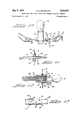
- FIG. 1 is a perspective View of a lamp -base in which one terminated end of a light-conducting member is disu posed;
- FIG. 2 is a view taken along lines 2--2 of FIG. l;
- FIG. 3 is a view taken along lines 3 3 of FIG. 1;
- FIG. 4 is a partially-sectioned view of a reflector carrying a light means and a terminated end of a light-conductE ing member defining a light pick-up device;
- FIG. 5 is a top plan ⁇ view of the light pick-up device of FIG. 4; r
- FIG. 6 is a View taken along lines 6-6 of FIG., 5;
- FIG. 7 is an embodiment of the light pick-up device of FIGS. 4 6; .t
- FIG. 8 is a perspective and exploded view of a display housing and terminated ends of a light-conducting member with one of the terminated ends being an alternative embodiment of FIGS. 4-6- and 7; J
- FIG. 9 is a cross-sectional view of the display housing with a terminated end of the light-conducting member in position therein;
- FIG. 10 is a view similar to FIG. 4 of the alternative light pick-up device
- FIG. 11 is a cross-sectional view of the light pick-up device of FIG. l0;
- FIG. 12 is a partial cross-sectional view of a further embodiment of a lamp 'base having a socket for receiving a termination member terminated to an end of a light conducting member;
- FIG. 13 is a side view of the termination member insertable in the socket of FIG. 12. i
- Body 1 has an annular internal surface 2 which merges into a conical surface 3, both of these surfaces merges into a conical surface 3, both of these surfaces being coated with a light reflective material.
- Conical surface 3 communcates with opening 4 which in turn communicates with opening S of less diameter thereby providing an interface 6 at the junction between openings 4 and 5.
- a lens member 7 is disposed in an annular recess 8 at the entrance to opening 4.
- a termination member 9 is secured to an end of a light-conducting member 10 and includes stop projections 11 at one end for engagement with body l to limit movement of the'termination member within opening 5 and spring lances 12 engage interface 6 to maintain termination member 9 within openings 4 and 5 and to properly position the end of light-conducting member 10 relative to lens member 7. Termination member 9 is completely disclosed in U.S. patent application Ser. No. 569,-
- Light-conducting member 10 is with flange of body 1 to hold ring 13 in position on body 1.
- a concentric ring 16 is connected to ring 13 by sections 17 and ring 16 includes a socket 18 into which base 19 of light bulb 20 is electrically connected by means of axially-spaced lugs 21 (only one being shown) which mate with L-shaped openings (not shown) in socket 18 to provide a conventional ⁇ bayonet connection, the stag gered location of lugs 21 in mateable engagement with the staggered short legs of the L-shaped openings thereby polarizing light bulb in socket 1S.
- Body 1 includes extensions 22 having channels 23 disposed therein and these channels merge into openings 24 in the part of body 1 containing annular surface 2.
- Recesses 25 are located in each side of channels 23 and in communication therewith.
- Electrical terminals ET comprise ferrule sections 32, securing sections 33 and contact-engaging sections 34.
- Ferrule sections 32 are crimped onto the conductive porn tions and insulation of electrical wires 35.
- Securing sec-1 tions 33 have the edges thereof disposed in recesses 25 and struck-outlances 36 in engagement with stepped surfaces 31 to maintain electrical terminals in position within channels 23 in an insulated manner.
- Arcuate surfaces 29 have this configuration so that contact-engaging sections 34 are not over-stressed upon light bulb 20 being disposed in socket 18.
- Sections 34 of the electrical terminals in engagement with arcuate surfaces 29, the edges of securing sections 33 within recesses 25 and lances 36 in engagement with stepped surfaces 31 maintain the electrical terminals in position within channels 23 and the electrical terminals can be removed therefrom by moving lances 36 out of engagement with surfaces 31.
- lens member 7 When light bulb 20 is energized, light emanating therefrom is reflected from surfaces 2 and 3 into lens member 7 to collect the rehected light rays into light-conducting member 10 so that light can be transmitted therealong to a remote location to indicate the condition of light bulb 20.
- Lens member 7 and the light-conducting member in the light-carrying member constitute a light pickup device.
- FIG. 4 through 6 illustrate an embodiment of a light pick-up device.
- a light-reflection member 38 having a light socket 39 in which light bulb 40 is disposed via a conventional bayonet connection.
- a depression 41 is formed in member 38 and has an opening 42 therein whose axis is in alignment with filaments in light bulb 40.
- a light pick-up device 43 is removably mounted in opening 42 and. includes a bellshaped ferrule 44 and a holding member 45.
- Ferrule 44 has a bell-mouth 46 to facilitate the insertion of lightconducting member 47 within pickup-device 43.
- Ferrule 44 is crimped along portion 48 to form a corrugated crimp by crimping dies completely disclosed in U.S. Pat. No.
- Section 49 of ferrule 44 acts as a stop against which legs 5l)l of holding member 45 engage and section 49 iS bent into engagement with legs 50 to secure the legs in position therein.
- Holding member 45 is preferably triangular in cross section and each side has a spring memn ber 51 stamped outwardly therefrom and the spring memn bers springably engage opening 42 in depression 41 to maintain pick-up device 43 in position therein, Washer 52 is located adjacent section 49 to provide a seal.
- the outer end of holding member 45 is formed to provide an aperture 52 to that the end of light-conducting member 47 extends therethrough and is held in position therein.
- FIG. 7 illustrates an embodiment of FIGS. 4-6 of a light pick-up device 43a which comprises a plastic housing 53 and holding member 45a.
- Housing 53 has a tapered passageway 54 extending therethrough and in which lightconducting member 47a is disposed.
- the narrow part of passageway 54 is ultrasonically welded to the covering member of light-conducting member 47a in order to secure housing 53 and the covering together; however, light-conducting member 47a and housing 53 can be thermally or chemically secured together or in any other suitable manner.
- Holding member 45 is preferably round in cross section and the nose thereof is necked-down to form aperture 52a in which the end of light-conducting member 47a is positioned.
- Holding member 45a includes spring members 51a which are disposed at 90 intervals.
- Holding member 45a is disposed in ay channel 55 in body 53.
- Struckout lugs 56 in holding member 45a cooperate with depressions 57 in channel 55 to lock holding member 45a and housing 53 together, depressions 57 being formed in channel 55 when holding member 45a is disposed in channel 5S of body 53.
- Housing 53 abuts against one side of mounting panel 58 While holding member 45 is disposed through an opening 59 and spring members 51a maintain the pick-up device in position within the opening.
- a sealing gasket 60 is disposed in recess 61 in body 53 to pro- 'vide a sealo
- a light pick-up device 62 which is a further embodiment of the previous light pick-up devices, comprises a tubular member 63 into which light-conducting member 64 is disposed. The outer end of tubular member 63 is crimpable on the lightconducting member in the manner of termination member 9 of FIGS.
- tubular member 63 is bent at an angle so as to be directed toward light bulb 65 whose base 66 is mounted in light-reflection member 67, the angular disposition of the end of tubular member 63 being such so as to receive the optimum amount of light flux emanated from light bulb 65.
- a mounting member 68 is secured onto tubular member 63 and includes spring fingers 69 for frictionally engaging aperture 70 in light-reflection member 67 to maintain light pick-up device 62 in position.
- a sealing gasket 71 is disposed on spring fingers 69 for sealing engagement with member 67.
- a lens plate 74 having lens member 75 in alignment which each of pasn sageways 72 is disposed against surface 76 within display housing 77 and termination carrying member 73 is secured against lens plate 74 via screw means 78.
- the front of display housing 77 has openings 79 in alignment with corresponding lens members 75 to display the light being transmitted via the terminated light-conducting members therebehind.
- Termination members 9 properly position the ends of the light-conducting members relative to lens memn bers 75 for optimum light transmission therethrough. Such. a display arrangement as illustrated in FIGS. 8 and 9 can be fused in conjunction with the previously described embodiments.
- FIGS. 12 and 13 illustrate an additional embodiment of the invention.
- Terminals 83 are connected to electrical wires 86 and they like light-conducting member 87 extend through light base 80 and out through a hole 88 therein so that'the terminated end of light-conducting member 87 is disposed in a socket 89 which is preferably formed as part of "light base 80 to properly align the end of the light conducting member for receiving light emanating from light bulb 81.
- Heat shrinkable plastic 90 is shrunk onto electrical wire 86 and light-conducting member 87 and the end of light base 80.
- a mounting member 91 similar to mounting member 68 in FIGS. 8 through 11 is used to mount light base 80 within an aperture 92 of mounting means 93 and a sealing gasket is disposed on the spring lingers of the mounting member to form a seal.
- Termination member 94 has a projection 95 to limit the movement of termination member 94 within socket 89.
- Ser.l No. 569,726, to provide' tensile and anti-torque char acteristics, the crimping being effected in the same manm ner as the teaching of application Ser. No. 557.797.
- Termination member 94 has a U-shape prior to crimping and crimping is eected by split die means on each side of spring mem bers 98.
- Monitoring with light-conducting assemblies ofthe type disclosed hereinabove provides reliability to indicate the status of light-producing devices because the light-conduct ing members sense the light output and routeI it to a readily visable area.
- a termination member secura'ble on an end of a light-conducting member comprising a U-shaped ferrule member having a first section provided with apertures and a second section provided with diamond-shaped openings dening spring means therebetween, said apertures having inwardly-directed means therearound, said ferrule member9 upon controllable crimping pressure being applied thereto. being crimped onto said light-conducting member without impairing the light transmitting characteristics thereof, said. inwardly-directed means biting into said light-conducting means thereby providing tensile and anti-torque characteristics.
- a lamp base for an electric light bulb comprising, a body member having a cavity directed inwardly from one end thereof and having an internally reflective wall9 a lamp socket, means adjacent the rim of the cavity for supporting the socket therewithin with the socket opening facing outwardly of said end of the body member to retain a bulb therein having its light emitting portion outwardly of the cavity.
- said means and socket being dimensioned relative to the cavity to allow light rays from the bulb to pass into the cavity.
- light conducting means having one end disposed in the body member and eX- posed to the interior of the cavity to receive the light rays from the bulb that are reflected from the cavity wall.
- a lamp base according to claim 3 in which the Ibottom of the cavity terminates in. a conical portion having its small end remote from the rim of the cavity, the one end of the light conducting means being disposed in the small end of said conical portion.
- a lamp base according to claim 4 including a lens in the small end. of the conical portion between the open end of the cavity and said one end of the light conductmg means.
- a lamp base according to claim 3. in which the body member is of dielectric material and is provided with an elongated slot in the outer surface thereof and an opening leading from the slot into the cavity, and a subn stantially L-shaped electrical conducting. member having one leg thereof disposed in the slot and the other leg disposed in the cavity to provide electrical contact means for a bulb terminal.
- a lamp base according to claim 6 in which the leg of the conductive member within the cavity is resilient for making pressure contact with a. bulb terminal.
Description
May 5, i Y 3,510,641
LIGHT BASE AND LIGHT-CONDCTING MEMBER ATTACHE) THERETO Filed March 27. 1967 3 Sheets-Sheet 1 May 5, 1970 c. E. REYNOLDS LIGHT BASE AND LIGHT-CONDUCTING MEMBER ATTACHED THERETO I5 Sheets-Shet 2 Filed March 27, 1967 May 5, 1970 c. E. ARl-:YNQLDS LIGHC| BASE AND LIGHT-CONDUCTING MEMBER ATTACHED THERETO 3 Sheets-Sheet 3 Filed March 27. 1967 "United States Patent O 3,510,641 LIGHT BASE AND LIGHT-CONDUCTING MEMBER ATTACHED THERETO Charles Edward Reynolds, Harrisburg, Pa., assigner to AMP Incorporated, Harrisburg, Pa. Filed Mar. 27, 1967, Ser. No. 626,251 Int. Clo G02b 5/16 U.S. Cl. 240--1 7 Claims ABSTRACT F THE DISCLOSURE A light base in which a light-emitting source is disposed for electrical energization A light conductor is mounted on the light base so as to receive light from a reflection area provided by the light base when the light-emitting source is energized to thereby indicate the condition of the light-emitting source. A terminating device is con=l trollably fastened on an end of the light conductor to removably mount the terminated end of the light conducl tor in position to receive light emitted by the light-emitting source.
This invention relates to a light base and more particularly to a light base having a light-conducting member attached thereto.
It is important in lighting systems to know the condition of each light. In the case of the lights of a vehicle, the fact that one of the headlights, one or both of the taillights or brakelights, or one of the front or rear turn indicator lights will not work creates driving hazards that are extremely dangerous. The condition of running lights on ships and airplanes is equally important. In a number of cases, the condition of lights of a lighting system can not be determined because of the location of the lights with respect to an operator, therefore monitoring of the lights of a lighting system is highly desirable and in some cases essential.
An object of the invention is to provide light means having a light-monitoring means to indicate the condition of the light means.
Another object of the invention is the provision of a lamp base having light-monitoring means mounted thereonu A further object of the invention is to provide lightmonitoring means removably mounted in a lamp base and being positioned to receive light emanating from a light source.
An additional object of the invention is the provision of a light-monitoring means having one end secured on a lamp base in a position to receive light emitted by the lighting means.
A still further object of the invention is to provide a splash-proof light-monitoring means to prevent water from entering the lampcarrying means.
Other objects and attainments of the present invention will become apparent to those skilled in the art upon a. reading of the following detailed description when taken in conjunction with the drawings in which there are shown and described illustrative embodiments of theinvention; it is to be understood, however, that these embodiments are not intended to be exhaustive nor limiting of the in venton but are given for purposes of illustration in order that others skilled in the art may fully understand the invention and the principles thereof and the manner of applying it in practical use so that they may modify it in various forms, each as may -be best suited to the condi= tions of a particular use.
The foregoing and other objects are achieved by a vpreferred embodiment of a termination mem-ber securable on an end of a light-conducting means comprising a fer- 3,5 l @,bdll Patented May 5, l 9?@ ICC rule member for engagement with the light-conducting means under controlled conditions to secure the ferrule member on the end of the light-conducting means with a minimum of reduction of the light-transmitting characn teristics of the light-conducting means, and means on the ferrule member for securing the ferrule member in an opening of a light carrying means with the end ofthe lightconducting means being directed toward a light source in the light carrying means.
In the drawings:
FIG. 1 is a perspective View of a lamp -base in which one terminated end of a light-conducting member is disu posed;
FIG. 2 is a view taken along lines 2--2 of FIG. l;
FIG. 3 is a view taken along lines 3 3 of FIG. 1;
FIG. 4 is a partially-sectioned view of a reflector carrying a light means and a terminated end of a light-conductE ing member defining a light pick-up device; f
FIG. 5 is a top plan `view of the light pick-up device of FIG. 4; r
FIG. 6 is a View taken along lines 6-6 of FIG., 5;
FIG. 7 is an embodiment of the light pick-up device of FIGS. 4 6; .t
FIG. 8 is a perspective and exploded view of a display housing and terminated ends of a light-conducting member with one of the terminated ends being an alternative embodiment of FIGS. 4-6- and 7; J
FIG. 9 is a cross-sectional view of the display housing with a terminated end of the light-conducting member in position therein;
FIG. 10 is a view similar to FIG. 4 of the alternative light pick-up device;
FIG. 11 is a cross-sectional view of the light pick-up device of FIG. l0;
FIG. 12 is a partial cross-sectional view of a further embodiment of a lamp 'base having a socket for receiving a termination member terminated to an end of a light conducting member; and
FIG. 13 is a side view of the termination member insertable in the socket of FIG. 12. i
Turning now to the drawings and especially FIGS. l through 3, light-carrying member LCM comprises a di-= electric body 1 molded from any suitable dielectric material in accordance with conventional molding techniques. Body 1 has an annular internal surface 2 which merges into a conical surface 3, both of these surfaces merges into a conical surface 3, both of these surfaces being coated with a light reflective material. Conical surface 3 communcates with opening 4 which in turn communicates with opening S of less diameter thereby providing an interface 6 at the junction between openings 4 and 5. A lens member 7 is disposed in an annular recess 8 at the entrance to opening 4. A termination member 9 is secured to an end of a light-conducting member 10 and includes stop projections 11 at one end for engagement with body l to limit movement of the'termination member within opening 5 and spring lances 12 engage interface 6 to maintain termination member 9 within openings 4 and 5 and to properly position the end of light-conducting member 10 relative to lens member 7. Termination member 9 is completely disclosed in U.S. patent application Ser. No. 569,-
`726, liled Aug. 2, 1966. Light-conducting member 10 is with flange of body 1 to hold ring 13 in position on body 1. A concentric ring 16 is connected to ring 13 by sections 17 and ring 16 includes a socket 18 into which base 19 of light bulb 20 is electrically connected by means of axially-spaced lugs 21 (only one being shown) which mate with L-shaped openings (not shown) in socket 18 to provide a conventional `bayonet connection, the stag gered location of lugs 21 in mateable engagement with the staggered short legs of the L-shaped openings thereby polarizing light bulb in socket 1S.
Electrical terminals ET comprise ferrule sections 32, securing sections 33 and contact-engaging sections 34. Ferrule sections 32 are crimped onto the conductive porn tions and insulation of electrical wires 35. Securing sec-1 tions 33 have the edges thereof disposed in recesses 25 and struck-outlances 36 in engagement with stepped surfaces 31 to maintain electrical terminals in position within channels 23 in an insulated manner.
Contact-engaging sections 34 are disposed in engage= ment with arcuate surfaces 29 so that contacts 37 on light bulb 20 engage respective ones thereof. Arcuate surfaces 29 have this configuration so that contact-engaging sections 34 are not over-stressed upon light bulb 20 being disposed in socket 18.
When light bulb 20 is energized, light emanating therefrom is reflected from surfaces 2 and 3 into lens member 7 to collect the rehected light rays into light-conducting member 10 so that light can be transmitted therealong to a remote location to indicate the condition of light bulb 20. Lens member 7 and the light-conducting member in the light-carrying member constitute a light pickup device.
Some of the advantages of the light-carrying member of FIGS. l through 3 are: Tolerance control is excellent from the filament means to the end of the light-conducting member adjacent lens members 7, the bulb is easy to replace, the reliecting surfaces are protected within the body, the electrical terminals are snapped in place and they are readily replaceable, coil spring contacts are elimi nated and the leaf spring contact-engaging sections func-s tion to provide an excellent electrical connection, light= reflection areas and pick up is symmetrical about the light bulb, the light-reflection area is only slightly larger than the bulb diameter, and a large amount of light flux is available.
FIG. 4 through 6 illustrate an embodiment of a light pick-up device. In this embodiment there is illustrated a light-reflection member 38 having a light socket 39 in which light bulb 40 is disposed via a conventional bayonet connection. A depression 41 is formed in member 38 and has an opening 42 therein whose axis is in alignment with filaments in light bulb 40. A light pick-up device 43 is removably mounted in opening 42 and. includes a bellshaped ferrule 44 and a holding member 45. Ferrule 44 has a bell-mouth 46 to facilitate the insertion of lightconducting member 47 within pickup-device 43. Ferrule 44 is crimped along portion 48 to form a corrugated crimp by crimping dies completely disclosed in U.S. Pat. No. 2,639,754. The crimp is performed in accordance with the teaching in the above-mentioned patent application Ser. No. 557,.797 to effect good mechanical connection on the covering member of the light-conducting member while maintaining the light-conducting characteristics of the light-conducting member at close to its maximum light-conducting condition.
FIG. 7 illustrates an embodiment of FIGS. 4-6 of a light pick-up device 43a which comprises a plastic housing 53 and holding member 45a. Housing 53 has a tapered passageway 54 extending therethrough and in which lightconducting member 47a is disposed. The narrow part of passageway 54 is ultrasonically welded to the covering member of light-conducting member 47a in order to secure housing 53 and the covering together; however, light-conducting member 47a and housing 53 can be thermally or chemically secured together or in any other suitable manner.
Holding member 45 is preferably round in cross section and the nose thereof is necked-down to form aperture 52a in which the end of light-conducting member 47a is positioned. Holding member 45a includes spring members 51a which are disposed at 90 intervals. Holding member 45a is disposed in ay channel 55 in body 53. Struckout lugs 56 in holding member 45a cooperate with depressions 57 in channel 55 to lock holding member 45a and housing 53 together, depressions 57 being formed in channel 55 when holding member 45a is disposed in channel 5S of body 53. Housing 53 abuts against one side of mounting panel 58 While holding member 45 is disposed through an opening 59 and spring members 51a maintain the pick-up device in position within the opening. A sealing gasket 60 is disposed in recess 61 in body 53 to pro- 'vide a sealo Turning now to FIGS. 8 through 1l, a light pick-up device 62, which is a further embodiment of the previous light pick-up devices, comprises a tubular member 63 into which light-conducting member 64 is disposed. The outer end of tubular member 63 is crimpable on the lightconducting member in the manner of termination member 9 of FIGS. l through 3, and the crimped end of tubular member 63 is bent at an angle so as to be directed toward light bulb 65 whose base 66 is mounted in light-reflection member 67, the angular disposition of the end of tubular member 63 being such so as to receive the optimum amount of light flux emanated from light bulb 65. A mounting member 68 is secured onto tubular member 63 and includes spring fingers 69 for frictionally engaging aperture 70 in light-reflection member 67 to maintain light pick-up device 62 in position. A sealing gasket 71 is disposed on spring fingers 69 for sealing engagement with member 67.
The other end of light-conducting member 64 is termispitten nated by termination member 9 which is secured in a pas= sageway 72 of a termination carrying member 73 by means of projections 11 and spring lances 12. A lens plate 74 having lens member 75 in alignment which each of pasn sageways 72 is disposed against surface 76 within display housing 77 and termination carrying member 73 is secured against lens plate 74 via screw means 78. The front of display housing 77 has openings 79 in alignment with corresponding lens members 75 to display the light being transmitted via the terminated light-conducting members therebehind. Termination members 9 properly position the ends of the light-conducting members relative to lens memn bers 75 for optimum light transmission therethrough. Such. a display arrangement as illustrated in FIGS. 8 and 9 can be fused in conjunction with the previously described embodiments.
FIGS. 12 and 13 illustrate an additional embodiment of the invention. This embodiment illustrates a light base 80 having a light bulb 81 connected therein via a conven= tional bayonet connection; Contact members 82 of light bulb 81 are in electrical engagement with electrical ter= minals 83 which are mounted in a dielectric member 84 which is spring-biased by a coil spring 85 to maintain electrical terminals 83 in electrical engagement with contact members 82. Terminals 83 are connected to electrical wires 86 and they like light-conducting member 87 extend through light base 80 and out through a hole 88 therein so that'the terminated end of light-conducting member 87 is disposed in a socket 89 which is preferably formed as part of "light base 80 to properly align the end of the light conducting member for receiving light emanating from light bulb 81. I
Heat shrinkable plastic 90 is shrunk onto electrical wire 86 and light-conducting member 87 and the end of light base 80. A mounting member 91 similar to mounting member 68 in FIGS. 8 through 11 is used to mount light base 80 within an aperture 92 of mounting means 93 and a sealing gasket is disposed on the spring lingers of the mounting member to form a seal.
FIG. 13 illustrates a termination member 94 for termi nating the end of light-conducting member 87 and for en= gagement with socket 89. Termination member 94 has a projection 95 to limit the movement of termination member 94 within socket 89. Openings 96 are formed in ter`= mination member 94 and, around each opening on the inside surface of termination member 94 a truste-conical projection or serrations are formed to penetrate the cover= ing member of light-conducting member 87 when termina= tion member 94 is crimped thereon in accordance with the teaching of the above-mentioned co-pending application. Ser.l No. 569,726, to provide' tensile and anti-torque char= acteristics, the crimping being effected in the same manm ner as the teaching of application Ser. No. 557.797.
Diamond-shaped openings 97 are formed in termina= tion member 94 to provide therebetween arcuate-shaped spring members 98 which frictionally engage socket 89 to frictionally maintain the terminated end of light: conducta ing member 87 in position therein. Termination member 94 could be used in the passageways of termination carry= ing member 73 of FIGS. 8 and 9, if desired. Termination member 94 has a U-shape prior to crimping and crimping is eected by split die means on each side of spring mem bers 98.
Monitoring with light-conducting assemblies ofthe type disclosed hereinabove provides reliability to indicate the status of light-producing devices because the light-conduct ing members sense the light output and routeI it to a readily visable area.
It will, therefore, be appreciated. that the aforemen= tioned and other desirable objects have been achieved;
however. it should be emphasized that the particular ern- 6 bodirnents of the inventions which are shown and dea scribed herein, are intended as merely illustrative and not as restrictive of the invention.
The invention is claimed in accordance with the follown 1. A termination member secura'ble on an end of a light-conducting member comprising a U-shaped ferrule member having a first section provided with apertures and a second section provided with diamond-shaped openings dening spring means therebetween, said apertures having inwardly-directed means therearound, said ferrule member9 upon controllable crimping pressure being applied thereto. being crimped onto said light-conducting member without impairing the light transmitting characteristics thereof, said. inwardly-directed means biting into said light-conducting means thereby providing tensile and anti-torque characteristics.
2. A termination member according to claim 1 wherein projection means extend outwardly from said ferrule member.
3. A lamp base for an electric light bulb comprising, a body member having a cavity directed inwardly from one end thereof and having an internally reflective wall9 a lamp socket, means adjacent the rim of the cavity for supporting the socket therewithin with the socket opening facing outwardly of said end of the body member to retain a bulb therein having its light emitting portion outwardly of the cavity. said means and socket being dimensioned relative to the cavity to allow light rays from the bulb to pass into the cavity. and light conducting means having one end disposed in the body member and eX- posed to the interior of the cavity to receive the light rays from the bulb that are reflected from the cavity wall.
4. A lamp base according to claim 3 in which the Ibottom of the cavity terminates in. a conical portion having its small end remote from the rim of the cavity, the one end of the light conducting means being disposed in the small end of said conical portion.
5. A lamp base according to claim 4 including a lens in the small end. of the conical portion between the open end of the cavity and said one end of the light conductmg means.
6. A lamp base according to claim 3. in which the body member is of dielectric material and is provided with an elongated slot in the outer surface thereof and an opening leading from the slot into the cavity, and a subn stantially L-shaped electrical conducting. member having one leg thereof disposed in the slot and the other leg disposed in the cavity to provide electrical contact means for a bulb terminal.
7. A lamp base according to claim 6 in which the leg of the conductive member within the cavity is resilient for making pressure contact with a. bulb terminal.
References Cited UNlTED STATES PATENTS 2,286.0l4 tia/i942 'Rowe n S50-96 3.1l0l.4lll 8/1963 Richards mmmmmmm ...n 350-96 XR 3.358.136 .l2/1967 Greasley n.. '24o-52.1 XR. 3.423.58l. fil/i969 Baer.
2 l98y443 4/1940) Paul et al. u 24W-84 XR. 2.2103 l2 8/1940 Wood t,... 24U-152 XR (2.510.873 6/1950 Early ...museum 24U-152 .XR 3l3l.690 5/1964 Innis et al. l
NORTN ANSI-IER. Primary Examiner R. P. GREiNER. Assistant Examiner
Applications Claiming Priority (2)
| Application Number | Priority Date | Filing Date | Title |
|---|---|---|---|
| US56972666A | 1966-08-02 | 1966-08-02 | |
| US62625167A | 1967-03-27 | 1967-03-27 |
Publications (1)
| Publication Number | Publication Date |
|---|---|
| US3510641A true US3510641A (en) | 1970-05-05 |
Family
ID=24509583
Family Applications (1)
| Application Number | Title | Priority Date | Filing Date |
|---|---|---|---|
| US626251A Expired - Lifetime US3510641A (en) | 1966-08-02 | 1967-03-27 | Light base and light-conducting member attached thereto |
Country Status (6)
| Country | Link |
|---|---|
| US (1) | US3510641A (en) |
| DE (1) | DE1772062A1 (en) |
| ES (1) | ES352010A2 (en) |
| FR (1) | FR94644E (en) |
| GB (1) | GB1158694A (en) |
| NL (1) | NL6803998A (en) |
Cited By (13)
| Publication number | Priority date | Publication date | Assignee | Title |
|---|---|---|---|---|
| US3608999A (en) * | 1969-12-31 | 1971-09-28 | Corning Glass Works | Monitoring and indication system utilizing fiber optics |
| DE2147766A1 (en) * | 1970-09-21 | 1972-07-06 | Cavis Cavetti Isolati Spa | Cable connectors of metal for light guide cables |
| US3705756A (en) * | 1970-12-28 | 1972-12-12 | Amp Domestic Inc | Terminal member for light transmitting means |
| US3758189A (en) * | 1971-11-09 | 1973-09-11 | G Codrino | Metal cable terminal for light guiding cable |
| US3806225A (en) * | 1972-11-28 | 1974-04-23 | G Codrino | Terminal fastener for light-guide cables |
| US4081208A (en) * | 1977-01-17 | 1978-03-28 | General Motors Corporation | Optical and electrical conduit termination means for circuit board |
| US4186995A (en) * | 1978-03-30 | 1980-02-05 | Amp Incorporated | Light device, lens, and fiber optic package |
| US4355862A (en) * | 1979-09-01 | 1982-10-26 | Amp Incorporated | Optical fibre termination |
| US4534616A (en) * | 1982-05-24 | 1985-08-13 | Amp Incorporated | Fiber optic connector having lens |
| US4668045A (en) * | 1983-01-03 | 1987-05-26 | Gte Laboratories Incorporated | Optical fiber centering device |
| US4986625A (en) * | 1985-12-26 | 1991-01-22 | Amp Incorporated | Optical fiber connector with retainer |
| US5072616A (en) * | 1983-12-23 | 1991-12-17 | The Babcock & Wilcox Company | Fiber optic level alarm |
| US20030000880A1 (en) * | 1998-07-31 | 2003-01-02 | Alticor Inc (F/K/A Amway Corporation) | Point-of-use water treatment system |
Families Citing this family (1)
| Publication number | Priority date | Publication date | Assignee | Title |
|---|---|---|---|---|
| GB9514701D0 (en) * | 1995-07-18 | 1995-09-13 | Care Slade Wayne P | Brake light indicator |
Citations (8)
| Publication number | Priority date | Publication date | Assignee | Title |
|---|---|---|---|---|
| US2198443A (en) * | 1938-06-21 | 1940-04-23 | John E Paul | Light indicator |
| US2210312A (en) * | 1938-05-20 | 1940-08-06 | Blake Mfg Corp | Flashlight |
| US2286014A (en) * | 1941-01-28 | 1942-06-09 | Stanley S Lieberman | Airplane angle indicator |
| US2510873A (en) * | 1943-10-16 | 1950-06-06 | Standard Thomson Corp | Light filter |
| US3101411A (en) * | 1960-05-17 | 1963-08-20 | American Optical Corp | Light conducting device to transmit ultra-violet radiation for specimen fluorescenceunder a microscope |
| US3131690A (en) * | 1962-10-22 | 1964-05-05 | American Optical Corp | Fiber optics devices |
| US3358136A (en) * | 1965-03-04 | 1967-12-12 | Pressac Ltd | Dustproof lamp holder |
| US3423581A (en) * | 1966-10-26 | 1969-01-21 | Gen Motors Corp | Remote illumination apparatus |
-
1967
- 1967-03-27 US US626251A patent/US3510641A/en not_active Expired - Lifetime
-
1968
- 1968-03-11 GB GB11669/68A patent/GB1158694A/en not_active Expired
- 1968-03-21 NL NL6803998A patent/NL6803998A/xx unknown
- 1968-03-26 ES ES352010A patent/ES352010A2/en not_active Expired
- 1968-03-26 FR FR145424A patent/FR94644E/en not_active Expired
- 1968-03-26 DE DE19681772062 patent/DE1772062A1/en active Pending
Patent Citations (8)
| Publication number | Priority date | Publication date | Assignee | Title |
|---|---|---|---|---|
| US2210312A (en) * | 1938-05-20 | 1940-08-06 | Blake Mfg Corp | Flashlight |
| US2198443A (en) * | 1938-06-21 | 1940-04-23 | John E Paul | Light indicator |
| US2286014A (en) * | 1941-01-28 | 1942-06-09 | Stanley S Lieberman | Airplane angle indicator |
| US2510873A (en) * | 1943-10-16 | 1950-06-06 | Standard Thomson Corp | Light filter |
| US3101411A (en) * | 1960-05-17 | 1963-08-20 | American Optical Corp | Light conducting device to transmit ultra-violet radiation for specimen fluorescenceunder a microscope |
| US3131690A (en) * | 1962-10-22 | 1964-05-05 | American Optical Corp | Fiber optics devices |
| US3358136A (en) * | 1965-03-04 | 1967-12-12 | Pressac Ltd | Dustproof lamp holder |
| US3423581A (en) * | 1966-10-26 | 1969-01-21 | Gen Motors Corp | Remote illumination apparatus |
Cited By (26)
| Publication number | Priority date | Publication date | Assignee | Title |
|---|---|---|---|---|
| US3608999A (en) * | 1969-12-31 | 1971-09-28 | Corning Glass Works | Monitoring and indication system utilizing fiber optics |
| DE2147766A1 (en) * | 1970-09-21 | 1972-07-06 | Cavis Cavetti Isolati Spa | Cable connectors of metal for light guide cables |
| US3705756A (en) * | 1970-12-28 | 1972-12-12 | Amp Domestic Inc | Terminal member for light transmitting means |
| US3758189A (en) * | 1971-11-09 | 1973-09-11 | G Codrino | Metal cable terminal for light guiding cable |
| US3806225A (en) * | 1972-11-28 | 1974-04-23 | G Codrino | Terminal fastener for light-guide cables |
| US4081208A (en) * | 1977-01-17 | 1978-03-28 | General Motors Corporation | Optical and electrical conduit termination means for circuit board |
| US4186995A (en) * | 1978-03-30 | 1980-02-05 | Amp Incorporated | Light device, lens, and fiber optic package |
| US4355862A (en) * | 1979-09-01 | 1982-10-26 | Amp Incorporated | Optical fibre termination |
| US4534616A (en) * | 1982-05-24 | 1985-08-13 | Amp Incorporated | Fiber optic connector having lens |
| US4668045A (en) * | 1983-01-03 | 1987-05-26 | Gte Laboratories Incorporated | Optical fiber centering device |
| US5072616A (en) * | 1983-12-23 | 1991-12-17 | The Babcock & Wilcox Company | Fiber optic level alarm |
| US4986625A (en) * | 1985-12-26 | 1991-01-22 | Amp Incorporated | Optical fiber connector with retainer |
| US20030000880A1 (en) * | 1998-07-31 | 2003-01-02 | Alticor Inc (F/K/A Amway Corporation) | Point-of-use water treatment system |
| US20030000879A1 (en) * | 1998-07-31 | 2003-01-02 | Alticor Inc. | Point-of-use water treatment system |
| US20030006180A1 (en) * | 1998-07-31 | 2003-01-09 | Alticor Inc. (F/K/A/ Amway Corporation) | Point-of-use water treatment system |
| US20030010695A1 (en) * | 1998-07-31 | 2003-01-16 | Alticor Inc. (F/K/A Amway Corporation) | Point-of-use water treatment system |
| US20030019803A1 (en) * | 1998-07-31 | 2003-01-30 | Alticor Inc. (F/K/A Amway Corporation) | Point-of-use water treatment system |
| US6533930B1 (en) | 1998-07-31 | 2003-03-18 | Access Business Group International Llc | Point-of-use water treatment system |
| US6716345B2 (en) | 1998-07-31 | 2004-04-06 | Access Business Group International Llc | Point-of-use water treatment system |
| US6716343B2 (en) | 1998-07-31 | 2004-04-06 | Access Business Group International Llc | Point-of-use water treatment system |
| US6726839B2 (en) | 1998-07-31 | 2004-04-27 | Access Business Group International Llc | Point-of-use water treatment system |
| US6773587B2 (en) | 1998-07-31 | 2004-08-10 | Access Business Group International Llc | Point-of-use water treatment system |
| US6811691B2 (en) | 1998-07-31 | 2004-11-02 | Access Business Group International Llc | Point-of-use water treatment system |
| US6949185B2 (en) | 1998-07-31 | 2005-09-27 | Alticor Inc. | Point-of-use water treatment system |
| US20060021926A1 (en) * | 1998-07-31 | 2006-02-02 | Alticor Inc. | Point-of-use water treatment system |
| US7166216B2 (en) | 1998-07-31 | 2007-01-23 | Access Business Group International, Llc | Point-of-use water treatment system |
Also Published As
| Publication number | Publication date |
|---|---|
| DE1772062A1 (en) | 1971-01-14 |
| GB1158694A (en) | 1969-07-16 |
| ES352010A2 (en) | 1969-07-01 |
| NL6803998A (en) | 1968-09-30 |
| FR94644E (en) | 1969-09-19 |
Similar Documents
| Publication | Publication Date | Title |
|---|---|---|
| US3510641A (en) | Light base and light-conducting member attached thereto | |
| US5702176A (en) | Modular connector device | |
| US6325651B1 (en) | Light emitting device, socket device and lighting device | |
| KR900008573B1 (en) | Miniature lamp arrays having improved lamp retention features | |
| US5087213A (en) | Lamp socket | |
| US5967823A (en) | Structure for a belt light and an extension device therefor | |
| US3354454A (en) | One-piece signal housing | |
| US9912081B2 (en) | Lighted electrical connector housing | |
| GB2301953A (en) | Electrical connectors | |
| US6325661B1 (en) | Waterproof connector | |
| US3638008A (en) | Multiple light transmission from a single light source | |
| HU221363B1 (en) | Electric lamp | |
| EP0660464B1 (en) | Electric bulb socket | |
| US3604919A (en) | Illumination device for edgelighting transparent panels | |
| US5250874A (en) | Socketless lamp with spring side contacts | |
| US5637020A (en) | Socket for electrical elements | |
| JPH08102351A (en) | Lamp holder and its assembly method | |
| US6607293B2 (en) | Rear combination lamp | |
| US5800212A (en) | Plug-in type light bulb | |
| US3516087A (en) | Carrier for lamp and electrical terminals | |
| US4101187A (en) | Socket for wedge base bulbs | |
| US3746906A (en) | Adapter base for electric lamp | |
| US6905225B2 (en) | Floodlight and spotlight adapter and enclosure | |
| US3541381A (en) | Plug-in lighting assembly | |
| US3060401A (en) | Indicator light assembly |