US3528126A - Continuous production apparatus for hard core foam plates having rigid cover layers particularly on a polyurethane base - Google Patents
Continuous production apparatus for hard core foam plates having rigid cover layers particularly on a polyurethane base Download PDFInfo
- Publication number
- US3528126A US3528126A US747944A US3528126DA US3528126A US 3528126 A US3528126 A US 3528126A US 747944 A US747944 A US 747944A US 3528126D A US3528126D A US 3528126DA US 3528126 A US3528126 A US 3528126A
- Authority
- US
- United States
- Prior art keywords
- plates
- cover layers
- rigid cover
- supporting
- foam
- Prior art date
- Legal status (The legal status is an assumption and is not a legal conclusion. Google has not performed a legal analysis and makes no representation as to the accuracy of the status listed.)
- Expired - Lifetime
Links
Images

Classifications
-
- B—PERFORMING OPERATIONS; TRANSPORTING
- B29—WORKING OF PLASTICS; WORKING OF SUBSTANCES IN A PLASTIC STATE IN GENERAL
- B29C—SHAPING OR JOINING OF PLASTICS; SHAPING OF MATERIAL IN A PLASTIC STATE, NOT OTHERWISE PROVIDED FOR; AFTER-TREATMENT OF THE SHAPED PRODUCTS, e.g. REPAIRING
- B29C44/00—Shaping by internal pressure generated in the material, e.g. swelling or foaming ; Producing porous or cellular expanded plastics articles
- B29C44/20—Shaping by internal pressure generated in the material, e.g. swelling or foaming ; Producing porous or cellular expanded plastics articles for articles of indefinite length
- B29C44/30—Expanding the moulding material between endless belts or rollers
- B29C44/308—Thickness separators and side seals
-
- B—PERFORMING OPERATIONS; TRANSPORTING
- B29—WORKING OF PLASTICS; WORKING OF SUBSTANCES IN A PLASTIC STATE IN GENERAL
- B29C—SHAPING OR JOINING OF PLASTICS; SHAPING OF MATERIAL IN A PLASTIC STATE, NOT OTHERWISE PROVIDED FOR; AFTER-TREATMENT OF THE SHAPED PRODUCTS, e.g. REPAIRING
- B29C44/00—Shaping by internal pressure generated in the material, e.g. swelling or foaming ; Producing porous or cellular expanded plastics articles
- B29C44/20—Shaping by internal pressure generated in the material, e.g. swelling or foaming ; Producing porous or cellular expanded plastics articles for articles of indefinite length
- B29C44/30—Expanding the moulding material between endless belts or rollers
-
- B—PERFORMING OPERATIONS; TRANSPORTING
- B29—WORKING OF PLASTICS; WORKING OF SUBSTANCES IN A PLASTIC STATE IN GENERAL
- B29C—SHAPING OR JOINING OF PLASTICS; SHAPING OF MATERIAL IN A PLASTIC STATE, NOT OTHERWISE PROVIDED FOR; AFTER-TREATMENT OF THE SHAPED PRODUCTS, e.g. REPAIRING
- B29C44/00—Shaping by internal pressure generated in the material, e.g. swelling or foaming ; Producing porous or cellular expanded plastics articles
- B29C44/20—Shaping by internal pressure generated in the material, e.g. swelling or foaming ; Producing porous or cellular expanded plastics articles for articles of indefinite length
- B29C44/32—Incorporating or moulding on preformed parts, e.g. linings, inserts or reinforcements
- B29C44/326—Joining the preformed parts, e.g. to make flat or profiled sandwich laminates
-
- B—PERFORMING OPERATIONS; TRANSPORTING
- B29—WORKING OF PLASTICS; WORKING OF SUBSTANCES IN A PLASTIC STATE IN GENERAL
- B29L—INDEXING SCHEME ASSOCIATED WITH SUBCLASS B29C, RELATING TO PARTICULAR ARTICLES
- B29L2007/00—Flat articles, e.g. films or sheets
-
- B—PERFORMING OPERATIONS; TRANSPORTING
- B29—WORKING OF PLASTICS; WORKING OF SUBSTANCES IN A PLASTIC STATE IN GENERAL
- B29L—INDEXING SCHEME ASSOCIATED WITH SUBCLASS B29C, RELATING TO PARTICULAR ARTICLES
- B29L2009/00—Layered products
Definitions
- the invention relates to the manufacture of hard core foam plates that are coated with layers of cover leaves, plates or foil. More in particular, the invention provides apparatus for the continuous production of hard foam plates covered with rigid cover layers of material, where the starting material is introduced between plates of material that constitute the cover layers and which are continuously moved along by a conveyor at a vertical distance or spacing from one another.
- thermoplastic masses between which a finely grained thermoplastic mass is disposed, are continuously moved between conveyors or bands, while during this movement the thermoplastic masses are heated by heating elements and are thereby heated.
- An apparatus is furthermore known, by means of which hard foam plates are produced which are covered with flexible sheets or foils.
- These foils are introduced at the top and at the bottom into a device referred to as a double band installation, so that a liquid starting material can be introduced between them and foamed in the space defined by the foils.
- the lateral sealing is effected by suitable laterally applied foils. All foils are fed from large supply rolls and are conducted and guided in a suitable manner. Such guiding, especially turning, and manipulating is not possible with rigid cover layers.
- the invention is based on the fundamental problem, to provide an apparatus of the type mentioned above, by means of which hard foam plates having rigid cover sheets or layers can be made if one starts with an initial material that is introduced in liquid condition.
- the supporting elements preclude that the plates which already are equally spaced from one another by a wedge,
- the supporting is advantageously effected by the upper band of the so-called double band installation.
- the supporting elements may either be stationary or they may be constructed as supporting bands or webs which rotate synchronously with the plates or with the double bands.
- the supporting has to be accomplished in different ways, depending on the type of profile or outline or the final product. For example, if it is desired that the foam material which is introduced terminate laterally with the rigid cover layers, then the supporting elements must be brought out of the area between the plates before the mass of foam material is completely hardened, so that the foam pressure can still press the material laterally outwardly until final hardening takes place and to produce the desired profile.
- the supporting elements in the form of endless bands that are driven synchronously with the plates about rollers or pulleys, in which connection the rollers are arranged to be adjustable or displaceable out of the region of the rigid cover layers to make possible the outward displacement of the supporting elements.
- the supporting elements are advantageously guided out of the space between the plates, in a manner that this operation is terminated together with the hardening of the foam material.
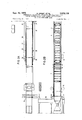
- FIGS. 1A and 1B show the apparatus for the production of hard foam plates covered with rigid cover layers in a side elevational view
- FIGS. 2A and 2B are plan views of the apparatus shown in FIGS. 1A and 1B where lateral supporting elements are provided in the region of the double band installation,
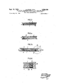
- FIG. 3 is an outline or profile of a hard foam plate covered with rigid cover layers, where the foam material which has been introduced terminates laterally with the rigid cover plates,
- FIG. 4 is an outline of a plate similar to that of FIG. 2, from which it differs in that the mass of foam introduced does not terminate laterally with the rigid cover layers,
- FIG. is a section through the double band installation with the lateral supporting element constructed in the form of supporting bands or straps,
- FIG. 6 is the detail A in accordance with FIG. 5, showing small features more completely,
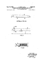
- FIG. 7 is a plan view of one side of the double conveyor installation in the area where a supporting belt is provided.
- FIG. 8 is a section along line VIII-VIII in FIG. 7 drawn to enlarged scale.
- FIGS. 1A and 1B illustrate the manner in which the rigid cover plates or layers 1, which may be of gypsum, asbestos-cement, plywood, sheet metal or hard fibrous material, are fed in pairs from a lifting table by way of a roller track onto a conveyor 4 made in any suitable manner.
- the conveyor 4 which operates in synchronism with the double band 11 conveys the superimposed plates to the plate connecting device 5, where the upper and correspondingly the lower plates are connected with one another at their abutting ends, which may be by means of agglutinant tape, such as masking tape.
- the tape strips may be provided with markings which later, at the end of the production process, can be probed or scanned by means of a probe, which then guides or controls the cross cutter for cutting the plates into sections at the abutment locations. It is not absolutely necessary, however, to provide such a probe, because the transverse cutter can also be controlled by a mechanical driver which, for example, may be a part or member of the conveyor 4 or cooperate with it.
- FIGS. 2A and 2B illustrates as one embodiment of supporting elements a supporting band or belt 18 which revolves about pulleys or rollers 21, 22, 23, and which is so arranged that it supports the upper plates 1, for example, to produce a section in accordance with FIG. 3, for the length of time required until the foam material between the plates is hardened sufliciently that supporting is no longer required, but the hardening must not have progressed to an extent that the foam pressure between the plates 1 after the supporting belts leave the space between them is no longer sufiicient to press the foam mass, or strips, if lateral limiting strips 9 are provided (FIG. 3), outwardly, so that in the resulting sections the rigid sides of the cover plates register with the corresponding sides of the hard foam core.
- stationary counter bearings 20 may be arranged between rollers or pulleys 21 and 22.
- the pulleys 24 may be pivotable or adjustable in such a manner that the exit of the supporting belt 18 out Of the space between the cover layers 1 can be changed as to time or location.
- the reversing rollers 22 can also be displaced parallel with respect to the conveying direction of the plates. In this manner a universal adjustability of the supporting belts is provided.
- FIGS. 5 and 6 illustrate a supporting belt 18 which is made of rubber that is vulcanized onto a steel strip or band 19.
- the stationary guide means 20 can simulta neously serve for the support of the belt 18 in vertical direction, which is accomplished by a suitable projection on the counter bearing 20 that extends into a groove provided in belt 18, 19.
- FIG. 7 illustrates the operative relationship between roller 24- and roller 22 for the purpose of guiding the supporting belt 18 out of the space between the plates 1.
- the direction of movement of the supporting band 18 between rollers 22 and 24 is inclined with respect to the direction of movement of the double band structure 11.
- the two dimension arrows indicate the differences in distance of the supporting belt 18 from the center line of the double band structure.
- the distance of the pulley or roller 24, and thus of the belt 18 which runs around the roller, from the center line is greater than the corresponding distance of the pulley or roller 22 from the center line.
- FIG. 7 aslo shows that the roller 24 is displaceable perpendicularly to the conveying direction in a slot as seen in FIG. 8.
- roller 22 is displaceable parallel to the feeding direction in an elongated slot in order to adjust the point of time at which the withdrawing of the supporting belt from the space between the plates begins.
- the foils 9, 12 and 13 are, of course, utilized in a manner depending on the desired type and configuration of the end product.
- the moving belt 18, :19 is suitably constructed and executed lateral cover strips can be dispensed with if it is prevented in another manner that the foam mass sticks to the belt. This can be achieved by the application of suitable chemical separating agents.
- the invention is not limited to the use of any particular kind of cover or side foils.
- Apparatus for the continuous production of hard foam plates covered by rigid cover layers or plates sealingly connected at their adjacent ends comprising conveyor means for continuously moving the cover plates at a vertical distance from one another, a foam supply means for introducting foam material in liquid from between the plates, a foamed plate conveyor disposed in receiving relationship to the plates discharged from the position of said foam supply means, limiting means applicable laterally on both sides between said plates adapted to prevent leakage of foam material, and supporting elements extending on both sides into the space below the upper of said plates adapted to carry the upper of said plates.
- Apparatus in accordance with claim 1 comprising a section of double bands or belts with supporting elements inclined relative to the direction of conveying.
- Apparatus in accordance with claim 2 comprising stationary counter bearings arranged on the side of said belt elements remote from the foam material.
- Apparatus in accordance with claim 2 comprising pulleys associated with said supporting belts arranged endwise of said foamed plate conveyor, where the supporting belt pulleys at the delivery end of the conveyor are adjustable for changing the inclination.
- Apparatus in accordance with claim 6, including intermediate pulleys between the end pulleys of said belts and means adapted to displace said pulleys parallel to the direction of conveying.
Description
CONTINUOUS PRODUCTION APPARATUS FOR HARD CORE FOAM PLATES HAVING RIGID COVER LAYERS PARTICULARLY ON A POLYURETHANE BASE Filed July 26 1968 4 Sheets-Sheet 2 FIG 2A FIG. 28
. Filed July 26 1968 Sept. 15, 1970 R. ERNST AL 3,528,126
CONTINUOUS PRODUCTI APPARA FOR HARD CORE F M PLATES HAV RI COVER LAYERS PARTICULARL A POLYURETHANE BASE 4 Sheets-Sheet 5 Sept. 15, 1970 v R. ERNST ETAL 3,528,126
CONTINUOUS PRODUCTION APPARATUS FOR HARD CORE FOAM PLATES HAVING RIGID COVER LAYERS PARTICULARLY ON A POLYURETHANE BASE Filed July 26, 1968 4 Sheets-Sheet 4 1a 52% 2L r 2! w r A VIII 2!. A L 2 f vm r- FIG. 7
. 21. 11 1a '7 ".11 'Yill"llll:1ll':i. L. 1
, mM/vraas I leuoouae/wr/r/w Knit-10.500607; r
United States CONTINUOUS PRODUCTION APPARATUS FOR HARD CORE FOAM PLATES HAVING RIGID COVER LAYERS PARTICULARLY ON A POLY- URETHANE BASE Rudolf Ernst, Strasslach, near Munich, and Karl-Josef Kraft, Leverkusen, Germany, assignors to Maschinenfabrik Hennecke Gesellschaft mit beschrankter Haftung, Leverkusen, Germany Filed July 26, 1968, Ser. No. 747,944 Int. Cl. B29d 7/08, 9/00 US. Cl. 18-4 7 Claims ABSTRACT OF THE DISCLOSURE Apparatus for the production of hard foam core plates having rigid cover plates or layers where the starting materials is introduced between the cover layers disposed at a vertical distance from one another which are moved continuously by a conveyor, where after the introduction of the foam material the upper plates which are connected to each other by sealing means are carried in the area between limiting foils on both sides by supporting disposed between the plates.
BACKGROUND OF THE INVENTION The invention relates to the manufacture of hard core foam plates that are coated with layers of cover leaves, plates or foil. More in particular, the invention provides apparatus for the continuous production of hard foam plates covered with rigid cover layers of material, where the starting material is introduced between plates of material that constitute the cover layers and which are continuously moved along by a conveyor at a vertical distance or spacing from one another.
An apparatus is already known where the rigid cover layers between which a finely grained thermoplastic mass is disposed, are continuously moved between conveyors or bands, while during this movement the thermoplastic masses are heated by heating elements and are thereby heated.
An apparatus is furthermore known, by means of which hard foam plates are produced which are covered with flexible sheets or foils. These foils are introduced at the top and at the bottom into a device referred to as a double band installation, so that a liquid starting material can be introduced between them and foamed in the space defined by the foils. Likewise, the lateral sealing is effected by suitable laterally applied foils. All foils are fed from large supply rolls and are conducted and guided in a suitable manner. Such guiding, especially turning, and manipulating is not possible with rigid cover layers.
SUMMARY OF THE INVENTION The invention is based on the fundamental problem, to provide an apparatus of the type mentioned above, by means of which hard foam plates having rigid cover sheets or layers can be made if one starts with an initial material that is introduced in liquid condition.
It is a particular object of the invention to provide an apparatus of the type aforementioned, by means of which hard foam plates on a polyurethane base covered with rigid cover layers can be produced with great accuracy.
This problem is solved in that the upper plates which are connected in a sealing manner at their abutment joints, are carried by supporting elements arranged on both sides between the plates in the area of laterally applied limiting foils after the introduction of the foam material.
The supporting elements preclude that the plates which already are equally spaced from one another by a wedge,
3,528,126 Patented Sept. 15, 1970 and between which the starting material is already present in liquid form, approach one another again, as a result of which the plates due to the hanging condition would have a distance from one another in vertical direction which would differ more or less from the desired and required spacing. This would result in a product which does not have the desired dimensions. It is, therefore, ascertained by means of these supporting elements that the upper plates cannot move in vertical direction, i.e., they cannot hang down, so that the spacing established between the upper and lower plates is maintained. The supporting elements are only effective until sufficient foaming has taken place and until the blown or foamed up material has taken over the carrying function. Until the foam material has become self supporting, or if it exerts a pressure against the upper plates that counteracts the gravity, supporting of the plates against this force is, of ocurse, necessary until the final hardening has taken place. The supporting is advantageously effected by the upper band of the so-called double band installation.
The supporting elements may either be stationary or they may be constructed as supporting bands or webs which rotate synchronously with the plates or with the double bands.
The supporting has to be accomplished in different ways, depending on the type of profile or outline or the final product. For example, if it is desired that the foam material which is introduced terminate laterally with the rigid cover layers, then the supporting elements must be brought out of the area between the plates before the mass of foam material is completely hardened, so that the foam pressure can still press the material laterally outwardly until final hardening takes place and to produce the desired profile.
Advantageously this is accomplished by constructing the supporting elements in the form of endless bands that are driven synchronously with the plates about rollers or pulleys, in which connection the rollers are arranged to be adjustable or displaceable out of the region of the rigid cover layers to make possible the outward displacement of the supporting elements.
Furthermore the supporting elements, respectively the supporting bands, are advantageously guided out of the space between the plates, in a manner that this operation is terminated together with the hardening of the foam material.
There may also be stationary counter bearings along the side of the supporting elements remote from the supporting elements.
If it is desired to produce an end product where the rigid cover layers project laterally beyond the foam material, then it is not necessary to bring the supporting elements out of the space between the rigid cover layers prior to the hardening.
BRIEF DESCRIPTION OF THE DRAWINGS Further objects and advantageous features of the invention will become apparent from the following description with reference to the accompanying drawings in which FIGS. 1A and 1B show the apparatus for the production of hard foam plates covered with rigid cover layers in a side elevational view,
FIGS. 2A and 2B are plan views of the apparatus shown in FIGS. 1A and 1B where lateral supporting elements are provided in the region of the double band installation,
FIG. 3 is an outline or profile of a hard foam plate covered with rigid cover layers, where the foam material which has been introduced terminates laterally with the rigid cover plates,
FIG. 4 is an outline of a plate similar to that of FIG. 2, from which it differs in that the mass of foam introduced does not terminate laterally with the rigid cover layers,
FIG. is a section through the double band installation with the lateral supporting element constructed in the form of supporting bands or straps,
FIG. 6 is the detail A in accordance with FIG. 5, showing small features more completely,
FIG. 7 is a plan view of one side of the double conveyor installation in the area where a supporting belt is provided, and
FIG. 8 is a section along line VIII-VIII in FIG. 7 drawn to enlarged scale.
FIGS. 1A and 1B illustrate the manner in which the rigid cover plates or layers 1, which may be of gypsum, asbestos-cement, plywood, sheet metal or hard fibrous material, are fed in pairs from a lifting table by way of a roller track onto a conveyor 4 made in any suitable manner. The conveyor 4 which operates in synchronism with the double band 11 conveys the superimposed plates to the plate connecting device 5, where the upper and correspondingly the lower plates are connected with one another at their abutting ends, which may be by means of agglutinant tape, such as masking tape. The tape strips may be provided with markings which later, at the end of the production process, can be probed or scanned by means of a probe, which then guides or controls the cross cutter for cutting the plates into sections at the abutment locations. It is not absolutely necessary, however, to provide such a probe, because the transverse cutter can also be controlled by a mechanical driver which, for example, may be a part or member of the conveyor 4 or cooperate with it.
Before the web which now consists of a tight upper and a tight lower plate layer is conducted of a further conveyor arrangement 7, it is possible to introduce the foils 9 for forming a pan for the liquid mass of foam material below the plates if such a cross section is desired. Thereupon the plates are spaced from one another in the desired manner, commencing at their common plane of contact, by means of sliding wedges or rollers 23. In this manner the lower web of plates can be passed under and the upper web can be passed over a charging or feeding device 10, whereupon the web enters the double band installation in which also foils or strips 12 for the lateral sealing can be introduced it the end product is to be of the type where the use of side foils, which may be paper is required. In addition the introduction of upper and lower cover foils 13 may be provided for in order to form a connection or seal with the bottom foil 9.
FIGS. 2A and 2B illustrates as one embodiment of supporting elements a supporting band or belt 18 which revolves about pulleys or rollers 21, 22, 23, and which is so arranged that it supports the upper plates 1, for example, to produce a section in accordance with FIG. 3, for the length of time required until the foam material between the plates is hardened sufliciently that supporting is no longer required, but the hardening must not have progressed to an extent that the foam pressure between the plates 1 after the supporting belts leave the space between them is no longer sufiicient to press the foam mass, or strips, if lateral limiting strips 9 are provided (FIG. 3), outwardly, so that in the resulting sections the rigid sides of the cover plates register with the corresponding sides of the hard foam core. In order to absorb the lateral pressure of the foam material stationary counter bearings 20 may be arranged between rollers or pulleys 21 and 22.
The pulleys 24 may be pivotable or adjustable in such a manner that the exit of the supporting belt 18 out Of the space between the cover layers 1 can be changed as to time or location. For this purpose the reversing rollers 22 can also be displaced parallel with respect to the conveying direction of the plates. In this manner a universal adjustability of the supporting belts is provided.
FIGS. 5 and 6 illustrate a supporting belt 18 which is made of rubber that is vulcanized onto a steel strip or band 19. The stationary guide means 20 can simulta neously serve for the support of the belt 18 in vertical direction, which is accomplished by a suitable projection on the counter bearing 20 that extends into a groove provided in belt 18, 19.
It is evident that it is not necessary for the purpose of producing sections in accordance with FIG. 5 to guide the supporting belt 18 out of the space between the rigid cover plates 1.
FIG. 7 illustrates the operative relationship between roller 24- and roller 22 for the purpose of guiding the supporting belt 18 out of the space between the plates 1. The direction of movement of the supporting band 18 between rollers 22 and 24 is inclined with respect to the direction of movement of the double band structure 11.
The two dimension arrows indicate the differences in distance of the supporting belt 18 from the center line of the double band structure. The distance of the pulley or roller 24, and thus of the belt 18 which runs around the roller, from the center line is greater than the corresponding distance of the pulley or roller 22 from the center line.
FIG. 7 aslo shows that the roller 24 is displaceable perpendicularly to the conveying direction in a slot as seen in FIG. 8. Similarly roller 22 is displaceable parallel to the feeding direction in an elongated slot in order to adjust the point of time at which the withdrawing of the supporting belt from the space between the plates begins.
The foils 9, 12 and 13 are, of course, utilized in a manner depending on the desired type and configuration of the end product. For example, if the moving belt 18, :19 is suitably constructed and executed lateral cover strips can be dispensed with if it is prevented in another manner that the foam mass sticks to the belt. This can be achieved by the application of suitable chemical separating agents. At any rate, the invention is not limited to the use of any particular kind of cover or side foils.
Having now described our invention with reference to the embodiments illustrated in the accompanying drawings, we do not wish to be limited thereto, but what we desire to protect by letters patent is set forth in the appended claims.
We claim:
1. Apparatus for the continuous production of hard foam plates covered by rigid cover layers or plates sealingly connected at their adjacent ends, comprising conveyor means for continuously moving the cover plates at a vertical distance from one another, a foam supply means for introducting foam material in liquid from between the plates, a foamed plate conveyor disposed in receiving relationship to the plates discharged from the position of said foam supply means, limiting means applicable laterally on both sides between said plates adapted to prevent leakage of foam material, and supporting elements extending on both sides into the space below the upper of said plates adapted to carry the upper of said plates.
2. Apparatus in accordance with claim 1, where said supporting elements are in the form of revolving continuous belt elements movable continuously 'with said plates.
3. Apparatus in accordance with claim 1, comprising a section of double bands or belts with supporting elements inclined relative to the direction of conveying.
4. Apparatus in accordance with claim 2, where said supporting elements are in the form of an endless steel band and an endless rub'ber belt vulcanized to the steel band.
5. Apparatus in accordance with claim 2 comprising stationary counter bearings arranged on the side of said belt elements remote from the foam material.
6. Apparatus in accordance with claim 2, comprising pulleys associated with said supporting belts arranged endwise of said foamed plate conveyor, where the supporting belt pulleys at the delivery end of the conveyor are adjustable for changing the inclination.
7. Apparatus in accordance with claim 6, including intermediate pulleys between the end pulleys of said belts and means adapted to displace said pulleys parallel to the direction of conveying.
Zimmer. Potchen et al. Means.
Oxel.
WILLIAM STEPHENSON, Primary Examiner
Applications Claiming Priority (2)
| Application Number | Priority Date | Filing Date | Title |
|---|---|---|---|
| DE1704828A DE1704828C3 (en) | 1966-12-01 | 1967-05-26 | Device for the continuous production of rigid foam panels laminated with rigid outer layers |
| US74794468A | 1968-07-26 | 1968-07-26 |
Publications (1)
| Publication Number | Publication Date |
|---|---|
| US3528126A true US3528126A (en) | 1970-09-15 |
Family
ID=25988058
Family Applications (1)
| Application Number | Title | Priority Date | Filing Date |
|---|---|---|---|
| US747944A Expired - Lifetime US3528126A (en) | 1967-05-26 | 1968-07-26 | Continuous production apparatus for hard core foam plates having rigid cover layers particularly on a polyurethane base |
Country Status (4)
| Country | Link |
|---|---|
| US (1) | US3528126A (en) |
| JP (1) | JPS5335105B1 (en) |
| FR (1) | FR1592519A (en) |
| GB (1) | GB1198393A (en) |
Cited By (27)
| Publication number | Priority date | Publication date | Assignee | Title |
|---|---|---|---|---|
| US3734668A (en) * | 1970-11-18 | 1973-05-22 | Upjohn Co | Apparatus for forming urethane foam stock |
| US3793122A (en) * | 1967-10-16 | 1974-02-19 | H Sullhofer | Device for producing in continuous process plates of polyurethane hard foam with covering plates |
| US4396791A (en) * | 1981-06-01 | 1983-08-02 | Mobay Chemical Corporation | Laminator thermocouple |
| US4606715A (en) * | 1982-12-17 | 1986-08-19 | Larson Roger E | Apparatus for making building panels in a continuous operation |
| WO2005028179A1 (en) * | 2003-09-19 | 2005-03-31 | Kingspan Research And Developments Limited | A panel |
| US20050161855A1 (en) * | 2004-01-23 | 2005-07-28 | Wade Brown | Continuous forming system utilizing up to six endless belts |
| US20050287238A1 (en) * | 2004-06-24 | 2005-12-29 | Taylor Zachary R | Continuous forming apparatus for three-dimensional foam products |
| EP1669176A2 (en) * | 2004-12-10 | 2006-06-14 | Sacmi Cooperativa Meccanici Imola Societa' Cooperativa | Improved pland for forming ceramic tiles or slabs |
| US20060186571A1 (en) * | 2004-01-23 | 2006-08-24 | Wade Brown | Filled polymer composite and synthetic building material compositions |
| EP1669177A3 (en) * | 2004-12-10 | 2006-11-08 | Sacmi Cooperativa Meccanici Imola Societa' Cooperativa | Improved plant for forming ceramic tiles or slabs |
| US20070225391A1 (en) * | 2006-03-24 | 2007-09-27 | Century-Board Usa, Llc | Polyurethane composite materials |
| US7794224B2 (en) | 2004-09-28 | 2010-09-14 | Woodbridge Corporation | Apparatus for the continuous production of plastic composites |
| US20110001255A1 (en) * | 2009-07-06 | 2011-01-06 | Boral Material Technologies Inc. | Vacuum Removal of Entrained Gasses In Extruded, Foamed Polyurethane |
| US20110002190A1 (en) * | 2009-07-06 | 2011-01-06 | Boral Material Technologies Inc. | Fiber Feed System For Extruder For Use In Filled Polymeric Products |
| US20110086931A1 (en) * | 2009-08-14 | 2011-04-14 | Boral Material Technologies Inc. | Polyurethanes derived from highly reactive reactants and coal ash |
| US20110086933A1 (en) * | 2009-08-14 | 2011-04-14 | Boral Material Technologies Inc. | Filled polyurethane composites and methods of making same |
| US20110086932A1 (en) * | 2009-08-14 | 2011-04-14 | Boral Material Technologies Inc. | Polyurethanes derived from lesquerella oil |
| US20110086934A1 (en) * | 2009-08-14 | 2011-04-14 | Boral Material Technologies Inc. | Filled polyurethane composites and methods of making same |
| CN104956012A (en) * | 2013-01-28 | 2015-09-30 | 万德墙材有限公司 | Machine and manufacturing method for building board |
| US9745224B2 (en) | 2011-10-07 | 2017-08-29 | Boral Ip Holdings (Australia) Pty Limited | Inorganic polymer/organic polymer composites and methods of making same |
| US9752015B2 (en) | 2014-08-05 | 2017-09-05 | Boral Ip Holdings (Australia) Pty Limited | Filled polymeric composites including short length fibers |
| US9932457B2 (en) | 2013-04-12 | 2018-04-03 | Boral Ip Holdings (Australia) Pty Limited | Composites formed from an absorptive filler and a polyurethane |
| US9988512B2 (en) | 2015-01-22 | 2018-06-05 | Boral Ip Holdings (Australia) Pty Limited | Highly filled polyurethane composites |
| US10030126B2 (en) | 2015-06-05 | 2018-07-24 | Boral Ip Holdings (Australia) Pty Limited | Filled polyurethane composites with lightweight fillers |
| US10138341B2 (en) | 2014-07-28 | 2018-11-27 | Boral Ip Holdings (Australia) Pty Limited | Use of evaporative coolants to manufacture filled polyurethane composites |
| US10472281B2 (en) | 2015-11-12 | 2019-11-12 | Boral Ip Holdings (Australia) Pty Limited | Polyurethane composites with fillers |
| FR3130677A1 (en) * | 2021-12-22 | 2023-06-23 | Gaztransport Et Technigaz | Method of production of an insulating panel by a production machine. |
Families Citing this family (5)
| Publication number | Priority date | Publication date | Assignee | Title |
|---|---|---|---|---|
| US4051209A (en) * | 1975-04-22 | 1977-09-27 | Kornylak Corporation | Continuous rigid foam panel production |
| JPS5916617A (en) * | 1982-07-19 | 1984-01-27 | Nippon Steel Corp | On-line cooling device of thick steel plate |
| IT1154367B (en) * | 1982-11-30 | 1987-01-21 | Metecno Spa | PROCEDURE FOR THE CONTINUOUS MANUFACTURE OF DOUBLE-SIDED SELF-SUPPORTING SANDWICH PANELS WITH INTERPOSED INSULATING MATERIAL, EQUIPPED WITH RIGID SIDE CONTINUOUS JOINTS; PANELS OBTAINED |
| DE3928847A1 (en) * | 1989-08-31 | 1991-03-14 | Siempelkamp Gmbh & Co | Continuous press for mfg. polymeric belts - has upper and lower steel belts running around drums and also guided belts to prevent lateral polymer flow during processing |
| DE4035610A1 (en) * | 1990-11-09 | 1992-05-14 | Basf Ag | METHOD FOR PRODUCING FIBER COMPOSITES |
Citations (4)
| Publication number | Priority date | Publication date | Assignee | Title |
|---|---|---|---|---|
| US1465326A (en) * | 1922-08-04 | 1923-08-21 | Zimmer Paul | Machine for the manufacturing of sweetmeats |
| US2866730A (en) * | 1955-05-11 | 1958-12-30 | Haskelite Mfg Corp | Laminated panel and process for producing same |
| US2909804A (en) * | 1955-09-16 | 1959-10-27 | Perry G Means | Continuous hot pressing machine for the manufacture of compressed boards |
| US3262151A (en) * | 1964-09-30 | 1966-07-26 | Dyfoam Corp | Apparatus for molding plastic material |
-
1968
- 1968-05-24 GB GB24914/68A patent/GB1198393A/en not_active Expired
- 1968-05-27 FR FR1592519D patent/FR1592519A/fr not_active Expired
- 1968-05-27 JP JP3558268A patent/JPS5335105B1/ja active Pending
- 1968-07-26 US US747944A patent/US3528126A/en not_active Expired - Lifetime
Patent Citations (4)
| Publication number | Priority date | Publication date | Assignee | Title |
|---|---|---|---|---|
| US1465326A (en) * | 1922-08-04 | 1923-08-21 | Zimmer Paul | Machine for the manufacturing of sweetmeats |
| US2866730A (en) * | 1955-05-11 | 1958-12-30 | Haskelite Mfg Corp | Laminated panel and process for producing same |
| US2909804A (en) * | 1955-09-16 | 1959-10-27 | Perry G Means | Continuous hot pressing machine for the manufacture of compressed boards |
| US3262151A (en) * | 1964-09-30 | 1966-07-26 | Dyfoam Corp | Apparatus for molding plastic material |
Cited By (52)
| Publication number | Priority date | Publication date | Assignee | Title |
|---|---|---|---|---|
| US3793122A (en) * | 1967-10-16 | 1974-02-19 | H Sullhofer | Device for producing in continuous process plates of polyurethane hard foam with covering plates |
| US3734668A (en) * | 1970-11-18 | 1973-05-22 | Upjohn Co | Apparatus for forming urethane foam stock |
| US4396791A (en) * | 1981-06-01 | 1983-08-02 | Mobay Chemical Corporation | Laminator thermocouple |
| US4606715A (en) * | 1982-12-17 | 1986-08-19 | Larson Roger E | Apparatus for making building panels in a continuous operation |
| WO2005028179A1 (en) * | 2003-09-19 | 2005-03-31 | Kingspan Research And Developments Limited | A panel |
| US20120292809A1 (en) * | 2004-01-23 | 2012-11-22 | Century-Board Usa, Llc | Continuous forming system utilizing up to six endless belts |
| US7491351B2 (en) | 2004-01-23 | 2009-02-17 | Century-Board Usa Llc | Continuous forming system utilizing up to six endless belts |
| US7993553B2 (en) | 2004-01-23 | 2011-08-09 | Century-Board Usa Llc | Filled polymer composite and synthetic building material compositions |
| US20060186571A1 (en) * | 2004-01-23 | 2006-08-24 | Wade Brown | Filled polymer composite and synthetic building material compositions |
| US7993552B2 (en) | 2004-01-23 | 2011-08-09 | Century-Board Usa Llc | Filled polymer composite and synthetic building material compositions |
| US20050161855A1 (en) * | 2004-01-23 | 2005-07-28 | Wade Brown | Continuous forming system utilizing up to six endless belts |
| US20060273486A1 (en) * | 2004-01-23 | 2006-12-07 | Zachary Taylor | Continuous forming system utilizing up to six endless belts |
| US7794817B2 (en) | 2004-01-23 | 2010-09-14 | Century-Board Usa Llc | Filled polymer composite and synthetic building material compositions |
| US7211206B2 (en) | 2004-01-23 | 2007-05-01 | Century-Board Usa Llc | Continuous forming system utilizing up to six endless belts |
| US10086542B2 (en) | 2004-06-24 | 2018-10-02 | Century-Board Usa, Llc | Method for molding three-dimensional foam products using a continuous forming apparatus |
| US10889035B2 (en) | 2004-06-24 | 2021-01-12 | Century-Board Corporation | Method for molding three-dimensional foam products using a continuous forming apparatus |
| US20050287238A1 (en) * | 2004-06-24 | 2005-12-29 | Taylor Zachary R | Continuous forming apparatus for three-dimensional foam products |
| US7316559B2 (en) | 2004-06-24 | 2008-01-08 | Century-Board Usa, Llc | Continuous forming apparatus for three-dimensional foam products |
| US7651645B2 (en) | 2004-06-24 | 2010-01-26 | Century Products, Llc | Method for molding three-dimensional foam products using a continuous forming apparatus |
| US20070052128A1 (en) * | 2004-06-24 | 2007-03-08 | Taylor Zachary R | Method for molding three-dimensional foam products using a continuous forming apparatus |
| US7794224B2 (en) | 2004-09-28 | 2010-09-14 | Woodbridge Corporation | Apparatus for the continuous production of plastic composites |
| EP1669176A3 (en) * | 2004-12-10 | 2006-11-08 | Sacmi Cooperativa Meccanici Imola Societa' Cooperativa | Improved pland for forming ceramic tiles or slabs |
| EP1669177A3 (en) * | 2004-12-10 | 2006-11-08 | Sacmi Cooperativa Meccanici Imola Societa' Cooperativa | Improved plant for forming ceramic tiles or slabs |
| EP1669176A2 (en) * | 2004-12-10 | 2006-06-14 | Sacmi Cooperativa Meccanici Imola Societa' Cooperativa | Improved pland for forming ceramic tiles or slabs |
| US20070225391A1 (en) * | 2006-03-24 | 2007-09-27 | Century-Board Usa, Llc | Polyurethane composite materials |
| US9139708B2 (en) | 2006-03-24 | 2015-09-22 | Boral Ip Holdings Llc | Extrusion of polyurethane composite materials |
| US9512288B2 (en) | 2006-03-24 | 2016-12-06 | Boral Ip Holdings Llc | Polyurethane composite materials |
| US8138234B2 (en) | 2006-03-24 | 2012-03-20 | Century-Board Usa, Llc | Polyurethane composite materials |
| US8299136B2 (en) | 2006-03-24 | 2012-10-30 | Century-Board Usa, Llc | Polyurethane composite materials |
| US20080132611A1 (en) * | 2006-03-24 | 2008-06-05 | Century-Board Usa, Llc | Polyurethane composite materials |
| US20110001255A1 (en) * | 2009-07-06 | 2011-01-06 | Boral Material Technologies Inc. | Vacuum Removal of Entrained Gasses In Extruded, Foamed Polyurethane |
| US20110002190A1 (en) * | 2009-07-06 | 2011-01-06 | Boral Material Technologies Inc. | Fiber Feed System For Extruder For Use In Filled Polymeric Products |
| US20110086932A1 (en) * | 2009-08-14 | 2011-04-14 | Boral Material Technologies Inc. | Polyurethanes derived from lesquerella oil |
| US20110086933A1 (en) * | 2009-08-14 | 2011-04-14 | Boral Material Technologies Inc. | Filled polyurethane composites and methods of making same |
| US9481759B2 (en) | 2009-08-14 | 2016-11-01 | Boral Ip Holdings Llc | Polyurethanes derived from highly reactive reactants and coal ash |
| US20110086934A1 (en) * | 2009-08-14 | 2011-04-14 | Boral Material Technologies Inc. | Filled polyurethane composites and methods of making same |
| US20110086931A1 (en) * | 2009-08-14 | 2011-04-14 | Boral Material Technologies Inc. | Polyurethanes derived from highly reactive reactants and coal ash |
| US8846776B2 (en) | 2009-08-14 | 2014-09-30 | Boral Ip Holdings Llc | Filled polyurethane composites and methods of making same |
| US9745224B2 (en) | 2011-10-07 | 2017-08-29 | Boral Ip Holdings (Australia) Pty Limited | Inorganic polymer/organic polymer composites and methods of making same |
| CN104956012A (en) * | 2013-01-28 | 2015-09-30 | 万德墙材有限公司 | Machine and manufacturing method for building board |
| US20150360456A1 (en) * | 2013-01-28 | 2015-12-17 | Oneday Wall Ab | Machine and manufacturing method for building board |
| US9694566B2 (en) * | 2013-01-28 | 2017-07-04 | Oneday Wall Ab | Machine and manufacturing method for building board |
| CN104956012B (en) * | 2013-01-28 | 2019-08-20 | 万德墙材有限公司 | Machine and manufacturing method for building board |
| US10189234B2 (en) | 2013-01-28 | 2019-01-29 | Oneday Wall Ab | Machine and manufacturing method for building board |
| US9932457B2 (en) | 2013-04-12 | 2018-04-03 | Boral Ip Holdings (Australia) Pty Limited | Composites formed from an absorptive filler and a polyurethane |
| US10324978B2 (en) | 2013-04-12 | 2019-06-18 | Boral Ip Holdings (Australia) Pty Limited | Composites formed from an absorptive filler and a polyurethane |
| US10138341B2 (en) | 2014-07-28 | 2018-11-27 | Boral Ip Holdings (Australia) Pty Limited | Use of evaporative coolants to manufacture filled polyurethane composites |
| US9752015B2 (en) | 2014-08-05 | 2017-09-05 | Boral Ip Holdings (Australia) Pty Limited | Filled polymeric composites including short length fibers |
| US9988512B2 (en) | 2015-01-22 | 2018-06-05 | Boral Ip Holdings (Australia) Pty Limited | Highly filled polyurethane composites |
| US10030126B2 (en) | 2015-06-05 | 2018-07-24 | Boral Ip Holdings (Australia) Pty Limited | Filled polyurethane composites with lightweight fillers |
| US10472281B2 (en) | 2015-11-12 | 2019-11-12 | Boral Ip Holdings (Australia) Pty Limited | Polyurethane composites with fillers |
| FR3130677A1 (en) * | 2021-12-22 | 2023-06-23 | Gaztransport Et Technigaz | Method of production of an insulating panel by a production machine. |
Also Published As
| Publication number | Publication date |
|---|---|
| JPS5335105B1 (en) | 1978-09-25 |
| GB1198393A (en) | 1970-07-15 |
| FR1592519A (en) | 1970-05-19 |
Similar Documents
| Publication | Publication Date | Title |
|---|---|---|
| US3528126A (en) | Continuous production apparatus for hard core foam plates having rigid cover layers particularly on a polyurethane base | |
| US3065500A (en) | Method and apparatus for making coherent bodies from expandable granules of thermoplastic | |
| US5762980A (en) | Installation for the continuous production of boards of wood-based material | |
| US3174887A (en) | Method of producing a sandwich structure from a pair of foam coated sheets | |
| US4347281A (en) | Foam board having improved evenness and the method and apparatus for its continuous manufacture | |
| US3793122A (en) | Device for producing in continuous process plates of polyurethane hard foam with covering plates | |
| US3487143A (en) | Apparatus and method for the continuous casting of polyurethane flat belting | |
| US3984195A (en) | Continuous production of planar expanded polyurethane blocks | |
| JPS6139886B2 (en) | ||
| US3215581A (en) | Foaming apparatus | |
| US3435102A (en) | Method of and apparatus for making covered plates of polyurethane in a continuous process | |
| NZ199749A (en) | Forming polyurethane foam;foam moves upwards between upwardly moving webs | |
| US3702274A (en) | Process for making rigid polyurethane foam laminate | |
| US3837771A (en) | Apparatus for producing foamed resin-care web-faced laminates in continuous lengths | |
| US4108585A (en) | Apparatus for the continuous production of foam plastic blocks of rectangular cross-section | |
| US3644606A (en) | Process for the manufacture of foam slabs | |
| US4267135A (en) | Process and apparatus for the continuous molding of polymer foam bunstock having a substantially rectangular cross-section | |
| US4756860A (en) | Apparatus for manufacturing insulation panels | |
| US2893466A (en) | Method and apparatus for making cable reinforced conveyor belts | |
| US3586573A (en) | Apparatuses for making reinforced plates of synthetic resin | |
| US1261056A (en) | Reserve feed and splicing apparatus. | |
| US4082824A (en) | Method of producing continuous planar expanded polyurethane blocks | |
| US2939509A (en) | Plastic corrugating process and machine | |
| US3488800A (en) | Continuous molder | |
| KR920001608B1 (en) | Foaming method and apparatus for foam |