US3552079A - Laminated tongue and groove building element - Google Patents
Laminated tongue and groove building element Download PDFInfo
- Publication number
- US3552079A US3552079A US767425A US3552079DA US3552079A US 3552079 A US3552079 A US 3552079A US 767425 A US767425 A US 767425A US 3552079D A US3552079D A US 3552079DA US 3552079 A US3552079 A US 3552079A
- Authority
- US
- United States
- Prior art keywords
- beams
- timber
- tongue
- groove
- insulating material
- Prior art date
- Legal status (The legal status is an assumption and is not a legal conclusion. Google has not performed a legal analysis and makes no representation as to the accuracy of the status listed.)
- Expired - Lifetime
Links
Images

Classifications
-
- E—FIXED CONSTRUCTIONS
- E04—BUILDING
- E04B—GENERAL BUILDING CONSTRUCTIONS; WALLS, e.g. PARTITIONS; ROOFS; FLOORS; CEILINGS; INSULATION OR OTHER PROTECTION OF BUILDINGS
- E04B2/00—Walls, e.g. partitions, for buildings; Wall construction with regard to insulation; Connections specially adapted to walls
- E04B2/56—Load-bearing walls of framework or pillarwork; Walls incorporating load-bearing elongated members
- E04B2/70—Load-bearing walls of framework or pillarwork; Walls incorporating load-bearing elongated members with elongated members of wood
- E04B2/701—Load-bearing walls of framework or pillarwork; Walls incorporating load-bearing elongated members with elongated members of wood with integrated supporting and obturation function
- E04B2/702—Load-bearing walls of framework or pillarwork; Walls incorporating load-bearing elongated members with elongated members of wood with integrated supporting and obturation function with longitudinal horizontal elements
Definitions
- a building element comprising a panel-shaped insulating material extending between two timber half-beams, the whole element being formed as a beam with one o1' more tongues and grooves and with the insulating material extending in the full height of the beam from the bottom of a groove or a surface between two tongues to the opposite edge of the beam, and an angle joint between two walls made of building elements having notches round a neck section for mutual connection of the elements.
- the invention concerns a building element incorporat ⁇ ing a built-in insulating material.
- Walls which are built of logs Ijoined longitudinally by a system of tongue and groove with notches for corner joints but without a rigid framework, will sink for some time after the building has been erected. This sinking results from the dehydration of the timber and will continue for 1-2 years. A Wall which is two meters high will sink approx. 5 cm. If a log-house of the above-mentioned type is to be insulated, a system must be employed in which laths are fastened to each individual beam or log in order that the shrinking of the timber in each beam will not combine to produce a massive shrinking of the whole wall, but will remain distributed throughout the individual beam.
- the insulating material in this case is located between the laths. This method is expensive and diicult since it requires the extra lath structure, and there is a danger that leaks occur in the tongue-and-groove joints or in the corner joints. If the lath construction is to be avoided, there is by known methods only the alternative to wait 1 2 years before litting the insulation material until the timber has dried and the sinking of the walls is concluded.
- the object of the invention is to permit a quick and simple erection of well-insulated log-houses without requiring a rigid framework, and in such a manner that the characteristic construction of the said houses is retained, the beams or logs being visible from both sides of the wall, and the further object is to permit the construction of such houses in such a manner that they will in practice prove no more expensive than non-insulated loghouses of the same type.
- An essential feature of the building element according to the invention is that it comprises a timber beam with at least one tongue and groove, and that the insulating material is panel shaped and extends the full length of the beam, at least from the bottom of a groove or the surface between two tongues to the opposite edge of the beam.
- the insulating material is an expanded foam plastic material with considerable compressive strength and can be glued together with the two, for the most part symmetrical, halves of the timber beam.
- This provides a beam well insulated against heat and damp, which on account of the symmetrical structure can absorb a considerable vertical load.
- the plastic foam material does not shrink when the timber dries, i.e. even if timber in the log wall, constructed of horizontal building elements as in the invention, shrinks in drying, there is no risk that the tongue-groove joints or corner joints will leak.
- the plastic foam material prevents water from penetrating the Wall, which counteracts a reduction in the insulation properties of the timber itself, and at the same time restricts the damaging effects that might otherwise arise from rot.
- a preferred form of execution of the building element described in the invention is peculiar in that it has at least two tongues, formed by the insulating material having a longitudinal groove between the tongues of the surrounding timber beam, and by the insulating material on the opposite edge of the beam forming a projecting tongue between the walls of the groove formed by the surrounding components of the timber beam. This provides a tight joint between the layers of insulation in the individual beams, the insulation forming a continuous panel extending the full height of the wall.
- a form of execution of the building element described in the invention with one or more layers of insulating material is peculiar in that the element incorporates a tongue of timber running parallel to one or more tongues containing insulating material, the timber tongue being a permanent structural whole with the timber of the beam; corresponding grooves are cut in the opposite edge of the beam. This provides an insulated wall of great strength.
- An angle joint between two walls in a logahouse built up of alternately crossing beams, each with a notch round the neck of the beam so that each beam in one wall lits over the neck of a beam in the crossing wall, is according to the invention peculiar in that the layers of insulation in each beam extend at least all the way up to the upper and lower face of each neck section, and that the layers have such longitudinal dimensions as to subject them to strong compressive force in a transverse direction when the beams are hammered together in an angle joint. This ensures not only fine insulating properties but also com pletely sealed corner joints, which are equally important.
- a particularly tight angle joint caused by a relatively light compression of the insulating materials in the neck sections of the beams and a pressure of the insulating material against the transverse timber surface can, in accordance with the invention, be obtained by providing the beams with notches which in cross section at the neck section are roof-shaped or arched at the top and corresponding shaped or arched on the underside, the insulating matlrial projecting slightly from the profits of the timber notc BRIEF DESCRIPTION OF THE DRAWING The invention is described below with reference to the accompanying drawings where:
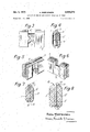
- FIG. 1 shows a beam-shaped building element executed in accordance with the invention
- FIG. 2 shows an angle joint made by building elements as illustrated in FIG. 1,
- FIGS. 3 and 4 show side and sectional views of the neck section of another form of execution of the building element in accordance with the invention, for ensuring an even tighter joint than that illustrated in FIG. 2,
- FIGS. 5 and 6 show portions of two beams with two different types of neck sections which, when the beams are hammered together in an angle joint, ensure that they form a flush lap joint, and
- FIGS. 7 and 8 show a cross section through another two forms of executions of the building element in accordance with the invention.
- FIGS. 1 and 2 are in the shape of beams with two symmetrical half-beam layers of timber 1 and 2, separated by an insulating layer of expanded plastic foam 3 to which they are glued.
- Layer 3 extends the full height of the beam from the bottom of a groove 4 to the upper side of a tongue 5 whose upright sides of wood form a part of each of the half-beams 1 and 2.
- the layer of insulation 3 also extends to the upper and lower faces of this neck section, ensuring that the walls are completely insulating without cold gaps at the corners and the insulating material helping to seal 4 the corner joints when the beams are hammered together as illustrated in FIG. 2.
- the beams illustrated in FIGS. 3 and 4 are similarly constructed of two halves 1 and 2, but have a familiar form of ridge-roof-shaped section 6, which works in conjunctions with a corresponding roof-shaped, transverse notch 7 in a crossing beam, ensuring increased seal properties.
- the insulating layer 3 between the halves can be easily compressed at the top of the roof-shaped neck section 6, being pressed into notch 7 and helping to increase the seal properties.
- FIGS. 5 and 6 show two beams which have neck sections 8 and 9 constructed differently, so that the beams can be hammered at right angles to each other until they lie on the same horizontal plane.
- This form of beam also has an intermediate layer of insulation 3 between the two symmetrical halves of the beams.
- This form permits the construction of a well-insulated house, sealed against the weather, which has beams laying at the same level all the way round the walls.
- This form is slightly more expensive than the aforementioned because of the two different types of neck sections.
- FIG. 7 shows a cross-section of a preferred form of execution of the building element described in the invention, with two half-beams 1 and 2 having an insulating layer 3 between them, which at the top between the sides 5 of the half-beams forms a groove 10 which can accommodate a tongue 11 on the beam above.
- Tongue 11 is designed in the insulating material 3 at the opposite edge of the beams so that it extends into the groove 4 formed by the two half-beams.
- the beam has two timber tongues 12 designed as part of the respective half-beams 1 and 2, and layer 3 extends upward between tongues 12 to form another tongue 13 which can be accommodated by a corresponding groove 14 in the opposite edge of the beam.
- the two half-beams can be mutually connected at long intervals by locating wedges in the space otherwise occupied by the layer of insulation. This would give the beams increased strength but would not reduce the beams insulating properties to any great extent.
- the beams would furthermore be made structurally more stable if the said wedges were located with their fibres pointing in the same direction as the libres in the halfbeams in order that the fibres can work in the same manner in the event of alteration in the moisture content of the timber.
- a laminated building element comprising a pair of wooden half-beams, a central panel of insulating material sandwiched between said wooden half-beams and having a heat transmission capacity less than that of said wooden half-beams, a recessed groove formed along one edge of said half-beams, a tongue comprising an extension of said central panel extending outwardly in said recessed groove and a second groove formed solely within one edge of said central panel along the edge of said beams opposite said tongue and having a width equal the thickness of said tongue whereby opposite edges of said building elements are matingly received with respect to each other to provide a wall-type construction.
- a laminated building element comprising a pair of wooden half-beams, a central panel formed of insulating material having a heat transmission capacity less than that of said half-beams and sandwiched between said halfheams wherein one edge of said half-beams is formed with a groove which extends along their length and the other edge of said half-beams adjacent said face is formed with a timber tongue extending outwardly in alignment with the respective groove of that half-beam and wherein said central panel is formed with an outwardly extending tongue along one edge adjacent the grooves of said halfbeams and an inwardly extending groove along its other edge inwardly spaced from said tongue of said half-beams.
Abstract
A BUILDING ELEMENT COMPRISING A PANEL-SHAPED INSULATING MATERIAL EXTENDING BETWEEN TWO TIMBER HALF-BEAMS, THE WHOLE ELEMENT BEING FORMED AS A BEAM WITH ONE OR MORE TONGUES AND GROOVES AND WITH THE INSULATING MATERIAL EXTENDING IN THE FULL HEIGHT OF THE BEAM FROM THE BOTTOM OF A GROOVE OR A SURFACE BETWEEN TWO TONGUE
THE OPPOSITE EDGE OF THE BEAM, AND AN ANGLE JOINT BETWEEN TWO WALLS MADE OF BUILDING ELEMENTS HAVING NOTCHES ROUND A NECK SECTION FOR MUTUAL CONNECTION OF THE ELEMENTS.
THE OPPOSITE EDGE OF THE BEAM, AND AN ANGLE JOINT BETWEEN TWO WALLS MADE OF BUILDING ELEMENTS HAVING NOTCHES ROUND A NECK SECTION FOR MUTUAL CONNECTION OF THE ELEMENTS.
Description
LAMINATED ToNGuE AND GROOVE BUILDING ELEMENT Filed O01.. 14, 1968 Jan. 54, 1971 A. MoRTENsl-:N
2 Sheets-Sheet l l 4 (tlldv/ INVENTOR. AACIE Morz'rt- NSEN BY musvcnbJwwticDnli wmnMce Arroz/JEVS LAMINATED ToNGUE AND GROOVE BUILDING ELEMENT Filed 001;. 14. 1968 Jan. 5, 1971 A. MORTENSEN 2 Sheets-Sheet 2 l Il INVENTOR. AAG: Mcnzreuss. N
)il Lmmume pTT/IVES United States Patent O 3,552,079 LAMINATED TONGUE AND GROOVE BUILDING ELEMENT Aage Mortensen, Hvidovre, Denmark, assignor to A/ S V. Jeppesens Savvaerk, Soborg, Denmark Filed Oct. 14, 1968, Ser. No. 767,425 Claims priority, application Denmark, Oct. 25, 1967, 5,323/ 67; Sweden, Nov. 8, 1967, 15,304/ 67 Int. Cl. E041 l/10; E04c 1/10, 2/24 U.S. Cl. 52-593 4 Claims ABSTRACT OF THE DISCLOSURE A building element comprising a panel-shaped insulating material extending between two timber half-beams, the whole element being formed as a beam with one o1' more tongues and grooves and with the insulating material extending in the full height of the beam from the bottom of a groove or a surface between two tongues to the opposite edge of the beam, and an angle joint between two walls made of building elements having notches round a neck section for mutual connection of the elements.
BACKGROUND OF THE INVENTION Field of the invention The invention concerns a building element incorporat` ing a built-in insulating material.
Description of the prior art Use is made in a number of forms of construction of laminated panels or sheets which incorporate a layer of insulating material but these panels are normally used only in houses erected by means of a rigid framework of columns on which the panels are fastened. In the case of timber houses and many other forms of houses the walls are usually insulated by placing panel insulation inside the wall proper and at some distance from it. This method is rather inconvenient and time-consuming, and in the case of log-houses the method conceals the inner surface of the log wall, which is undesirable both from the point of view of appearance and because the internal |wall and insulating material subsequently require considerable maintenance in the form of paint and paper. An open timber wall on the other hand requires almost no maintenance once it has been given a coat of preserving fluid, varnish or other substance. To avoid having to conceal the timber construction and thus retain the characteristic log-house eiect, architects have (with a View to making allowances for the climate and the fact that such houses are frequently used as summer and year-round accommodation) in the past employed such thick lengths of timber that the houses-although not insulated-are pleasant to live in. The use of such heavy timber at the current high cost of this material means however that the houses become relatively expensive, and the expense of heating houses of this type becomes quite considerable if houses, as is the practice increasingly, are employed not only as week-end accommodation in summer but also as leisuretime houses for year-round use.
Another problem connected with the insulation of logice houses constructed of horizontal beams is that the Walls, which are built of logs Ijoined longitudinally by a system of tongue and groove with notches for corner joints but without a rigid framework, will sink for some time after the building has been erected. This sinking results from the dehydration of the timber and will continue for 1-2 years. A Wall which is two meters high will sink approx. 5 cm. If a log-house of the above-mentioned type is to be insulated, a system must be employed in which laths are fastened to each individual beam or log in order that the shrinking of the timber in each beam will not combine to produce a massive shrinking of the whole wall, but will remain distributed throughout the individual beam. The insulating material in this case is located between the laths. This method is expensive and diicult since it requires the extra lath structure, and there is a danger that leaks occur in the tongue-and-groove joints or in the corner joints. If the lath construction is to be avoided, there is by known methods only the alternative to wait 1 2 years before litting the insulation material until the timber has dried and the sinking of the walls is concluded.
SUMMARY OF THE INVENTION The object of the invention is to permit a quick and simple erection of well-insulated log-houses without requiring a rigid framework, and in such a manner that the characteristic construction of the said houses is retained, the beams or logs being visible from both sides of the wall, and the further object is to permit the construction of such houses in such a manner that they will in practice prove no more expensive than non-insulated loghouses of the same type.
An essential feature of the building element according to the invention, is that it comprises a timber beam with at least one tongue and groove, and that the insulating material is panel shaped and extends the full length of the beam, at least from the bottom of a groove or the surface between two tongues to the opposite edge of the beam.
One advantage of employing building elements in the form of beams with inlaid insulating material his that, simply by hammering the beams together, the builder can erect an insulated, sealed wall quickly. And since the timber material in the middle of the beams is replaced by the cheaper insulating material, a saving of timber is effected to the extent that the beams, in spite of the extra work involved, can be manufactured at more or less the same price as an ordinary timber beam of the same dimensions.
In one embodiment of the invention, the insulating material is an expanded foam plastic material with considerable compressive strength and can be glued together with the two, for the most part symmetrical, halves of the timber beam. This provides a beam well insulated against heat and damp, which on account of the symmetrical structure can absorb a considerable vertical load. The plastic foam material does not shrink when the timber dries, i.e. even if timber in the log wall, constructed of horizontal building elements as in the invention, shrinks in drying, there is no risk that the tongue-groove joints or corner joints will leak. In addition the plastic foam material prevents water from penetrating the Wall, which counteracts a reduction in the insulation properties of the timber itself, and at the same time restricts the damaging effects that might otherwise arise from rot.
A preferred form of execution of the building element described in the invention is peculiar in that it has at least two tongues, formed by the insulating material having a longitudinal groove between the tongues of the surrounding timber beam, and by the insulating material on the opposite edge of the beam forming a projecting tongue between the walls of the groove formed by the surrounding components of the timber beam. This provides a tight joint between the layers of insulation in the individual beams, the insulation forming a continuous panel extending the full height of the wall.
A form of execution of the building element described in the invention with one or more layers of insulating material is peculiar in that the element incorporates a tongue of timber running parallel to one or more tongues containing insulating material, the timber tongue being a permanent structural whole with the timber of the beam; corresponding grooves are cut in the opposite edge of the beam. This provides an insulated wall of great strength.
An angle joint between two walls in a logahouse built up of alternately crossing beams, each with a notch round the neck of the beam so that each beam in one wall lits over the neck of a beam in the crossing wall, is according to the invention peculiar in that the layers of insulation in each beam extend at least all the way up to the upper and lower face of each neck section, and that the layers have such longitudinal dimensions as to subject them to strong compressive force in a transverse direction when the beams are hammered together in an angle joint. This ensures not only fine insulating properties but also com pletely sealed corner joints, which are equally important.
A particularly tight angle joint caused by a relatively light compression of the insulating materials in the neck sections of the beams and a pressure of the insulating material against the transverse timber surface can, in accordance with the invention, be obtained by providing the beams with notches which in cross section at the neck section are roof-shaped or arched at the top and corresponding shaped or arched on the underside, the insulating matlrial projecting slightly from the profits of the timber notc BRIEF DESCRIPTION OF THE DRAWING The invention is described below with reference to the accompanying drawings where:
FIG. 1 shows a beam-shaped building element executed in accordance with the invention,
FIG. 2 shows an angle joint made by building elements as illustrated in FIG. 1,
FIGS. 3 and 4 show side and sectional views of the neck section of another form of execution of the building element in accordance with the invention, for ensuring an even tighter joint than that illustrated in FIG. 2,
FIGS. 5 and 6 show portions of two beams with two different types of neck sections which, when the beams are hammered together in an angle joint, ensure that they form a flush lap joint, and
FIGS. 7 and 8 show a cross section through another two forms of executions of the building element in accordance with the invention.
The building elements shown in FIGS. 1 and 2 are in the shape of beams with two symmetrical half-beam layers of timber 1 and 2, separated by an insulating layer of expanded plastic foam 3 to which they are glued. Layer 3 extends the full height of the beam from the bottom of a groove 4 to the upper side of a tongue 5 whose upright sides of wood form a part of each of the half- beams 1 and 2. Near each or at places where the beams are to be assembled with beams in a transverse wall there is a neck section 6, and the layer of insulation 3 also extends to the upper and lower faces of this neck section, ensuring that the walls are completely insulating without cold gaps at the corners and the insulating material helping to seal 4 the corner joints when the beams are hammered together as illustrated in FIG. 2.
The beams illustrated in FIGS. 3 and 4 are similarly constructed of two halves 1 and 2, but have a familiar form of ridge-roof-shaped section 6, which works in conjunctions with a corresponding roof-shaped, transverse notch 7 in a crossing beam, ensuring increased seal properties. The insulating layer 3 between the halves can be easily compressed at the top of the roof-shaped neck section 6, being pressed into notch 7 and helping to increase the seal properties.
FIGS. 5 and 6 show two beams which have neck sections 8 and 9 constructed differently, so that the beams can be hammered at right angles to each other until they lie on the same horizontal plane. This form of beam also has an intermediate layer of insulation 3 between the two symmetrical halves of the beams. Thus, permits the construction of a well-insulated house, sealed against the weather, which has beams laying at the same level all the way round the walls. This form is slightly more expensive than the aforementioned because of the two different types of neck sections.
FIG. 7 shows a cross-section of a preferred form of execution of the building element described in the invention, with two half- beams 1 and 2 having an insulating layer 3 between them, which at the top between the sides 5 of the half-beams forms a groove 10 which can accommodate a tongue 11 on the beam above. Tongue 11 is designed in the insulating material 3 at the opposite edge of the beams so that it extends into the groove 4 formed by the two half-beams. When a number of beams are hammered together one above the other to form a wall the insulating material will form a sealed, continuous panel inside the whole wall, extending the full height of the latter.
In the form of execution illustrated in FIG. 8 the beam has two timber tongues 12 designed as part of the respective half- beams 1 and 2, and layer 3 extends upward between tongues 12 to form another tongue 13 which can be accommodated by a corresponding groove 14 in the opposite edge of the beam.
If desired, the two half-beams can be mutually connected at long intervals by locating wedges in the space otherwise occupied by the layer of insulation. This would give the beams increased strength but would not reduce the beams insulating properties to any great extent. The beams would furthermore be made structurally more stable if the said wedges were located with their fibres pointing in the same direction as the libres in the halfbeams in order that the fibres can work in the same manner in the event of alteration in the moisture content of the timber.
What is claimed is:
1. A laminated building element comprising a pair of wooden half-beams, a central panel of insulating material sandwiched between said wooden half-beams and having a heat transmission capacity less than that of said wooden half-beams, a recessed groove formed along one edge of said half-beams, a tongue comprising an extension of said central panel extending outwardly in said recessed groove and a second groove formed solely within one edge of said central panel along the edge of said beams opposite said tongue and having a width equal the thickness of said tongue whereby opposite edges of said building elements are matingly received with respect to each other to provide a wall-type construction.
2. The invention of claim 1 wherein said central panel is formed of foam plastic material.
3. A laminated building element comprising a pair of wooden half-beams, a central panel formed of insulating material having a heat transmission capacity less than that of said half-beams and sandwiched between said halfheams wherein one edge of said half-beams is formed with a groove which extends along their length and the other edge of said half-beams adjacent said face is formed with a timber tongue extending outwardly in alignment with the respective groove of that half-beam and wherein said central panel is formed with an outwardly extending tongue along one edge adjacent the grooves of said halfbeams and an inwardly extending groove along its other edge inwardly spaced from said tongue of said half-beams.
4. The invention of claim 3 wherein said central pane is formed of foam plastic material. r
References Cited UNITED STATES PATENTS 1,521,933 1/1925 Drake 287-20.92T+G 3,016,316 l/1962 `Olson 52-593 6 3,145,504 8/1964 Dunnington 52-309 3,257,762 6/ 1966 Steiner 52-233 FOREIGN PATENTS 582,430 1946 Great Britain 52-404 5 582,43() 1946 Great Britain 52-593 645,222 1962 Canada 52--233 1,373,787 1964 France 52-233 10 JOHN E. MURTAGH, Primary Examiner U.S. Cl. X.R. 52-233, 309
Applications Claiming Priority (2)
| Application Number | Priority Date | Filing Date | Title |
|---|---|---|---|
| DK532367A DK129667B (en) | 1967-10-25 | 1967-10-25 | Building element in the form of a layered beam with feather and groove. |
| SE15304/67A SE318984B (en) | 1967-11-08 | 1967-11-08 |
Publications (1)
| Publication Number | Publication Date |
|---|---|
| US3552079A true US3552079A (en) | 1971-01-05 |
Family
ID=26067817
Family Applications (1)
| Application Number | Title | Priority Date | Filing Date |
|---|---|---|---|
| US767425A Expired - Lifetime US3552079A (en) | 1967-10-25 | 1968-10-14 | Laminated tongue and groove building element |
Country Status (2)
| Country | Link |
|---|---|
| US (1) | US3552079A (en) |
| GB (1) | GB1225536A (en) |
Cited By (43)
| Publication number | Priority date | Publication date | Assignee | Title |
|---|---|---|---|---|
| US3919819A (en) * | 1973-02-06 | 1975-11-18 | Wayne H Oliver | Self locking panel connector |
| US3992838A (en) * | 1975-07-14 | 1976-11-23 | New England Log Homes, Inc. | Insulated wall log |
| US4096676A (en) * | 1977-07-18 | 1978-06-27 | Maurice Hibert | Wall member |
| US4147001A (en) * | 1977-11-07 | 1979-04-03 | Oliver Wayne H | Connector for wall panel structure |
| US4224774A (en) * | 1978-08-31 | 1980-09-30 | Rockwool International A/S | Composite building elements |
| US4277925A (en) * | 1979-05-04 | 1981-07-14 | Kinser C Wayne | Simulated log building structure |
| DE3006303A1 (en) * | 1980-02-20 | 1981-08-27 | Herbert 6000 Frankfurt Siller | Natural wood sectioned log cabin type beam - has trunk timber halves cut and aligned for max. basic material utilisation |
| US4503648A (en) * | 1982-12-09 | 1985-03-12 | Mahaffey Donald H | Lightweight composite building module |
| US4505085A (en) * | 1982-12-03 | 1985-03-19 | Oliver Wayne H | Split panel assembly |
| US4517780A (en) * | 1983-02-07 | 1985-05-21 | Lacombe Gerard A | Insulated wall unit construction |
| US4614071A (en) * | 1983-11-16 | 1986-09-30 | Sams Carl R | Building blocks |
| US4840003A (en) * | 1987-11-09 | 1989-06-20 | Hearthstone Builders, Inc. | Construction log and associated corner construction |
| US5103610A (en) * | 1990-02-12 | 1992-04-14 | Walters Victor R | Log building element |
| US5182892A (en) * | 1991-08-15 | 1993-02-02 | Louisiana-Pacific Corporation | Tongue and groove board product |
| US5325645A (en) * | 1989-11-23 | 1994-07-05 | True North Log Homes | Intersecting joint |
| US5599136A (en) * | 1993-04-07 | 1997-02-04 | Wilke; Douglas A. | Structure for topography stabilization and runoff control |
| WO1997016611A1 (en) * | 1994-05-04 | 1997-05-09 | Loef Roger | Building element and method for manufacturing a building element |
| WO1998015396A1 (en) * | 1996-10-07 | 1998-04-16 | Peter Sing | Laminated structural wood products and method |
| US6070376A (en) * | 1998-09-03 | 2000-06-06 | Asper; William D. | Interfitting wooden and log walls |
| US6145261A (en) * | 1998-03-20 | 2000-11-14 | Weyerhaeuser Company Limited | Tongue and groove board including a water drainage system |
| EP1184523A1 (en) * | 2000-08-31 | 2002-03-06 | Holzwerke Wimmer GmbH | Binding element made of wood and thermal insulation material |
| US20030136065A1 (en) * | 2000-04-17 | 2003-07-24 | Gjems Ole Reidar | Cogging element and cogging structure |
| US20050000176A1 (en) * | 2001-09-15 | 2005-01-06 | Morgenstern Richard C. | Cast log structure |
| US20050115177A1 (en) * | 2001-09-15 | 2005-06-02 | Richard Morgenstern | Cast log structure |
| US20060005500A1 (en) * | 2004-07-07 | 2006-01-12 | Vahak Hovnanian | Mortar less brick wall construction |
| US20070033901A1 (en) * | 2005-07-20 | 2007-02-15 | Sylvain Tiberi | Stackable insulated unit for wall construction and method |
| BE1016631A3 (en) * | 2005-06-09 | 2007-03-06 | Bofa Nv | Tongue and groove panel for insulated wooden walls, floors or roofs, comprises sandwich construction with wooden boards bonded together via insulation layer |
| NO20055945A (en) * | 2005-12-14 | 2007-06-11 | Leif Melvin Nettum | Building element with insulation |
| US20080053022A1 (en) * | 2006-07-13 | 2008-03-06 | Marschke Carl R | Hollow core floor and deck element |
| US20080083177A1 (en) * | 2005-07-20 | 2008-04-10 | Sylvain Tiberi | Stackable insulated unit for wall construction and method of fabrication thereof |
| US20080127583A1 (en) * | 2006-08-28 | 2008-06-05 | Wrightman Robert A | Log for log home |
| US20090056251A1 (en) * | 2007-08-28 | 2009-03-05 | Wrightman Robert A | Log wall connector system |
| US20090199497A1 (en) * | 2007-08-28 | 2009-08-13 | Wrightman Robert A | Log wall connector system |
| US7596916B1 (en) * | 2004-03-25 | 2009-10-06 | Richard Thomas Anderson | Multi beveled interlocking corner notch and associated anti settling system |
| US20090288362A1 (en) * | 2008-05-20 | 2009-11-26 | Remi Perron | Mounting method for a roof |
| GB2462854A (en) * | 2008-08-22 | 2010-02-24 | Wilsons Timber Co & Mfg Joiner | Box structure, especially a compost box or planter |
| US20100154334A1 (en) * | 2008-12-19 | 2010-06-24 | White Larry E | Wood-walled log structure having durable butt joints and method of manufacturing the same |
| US20100180527A1 (en) * | 2007-10-05 | 2010-07-22 | Hankook Styropol Co., Ltd | Constructive light weight insulation block and construction method thereof |
| US20110185662A1 (en) * | 2003-10-24 | 2011-08-04 | Exterior Portfolio, Llc | Foaming of simulated stone structures |
| US20110239573A1 (en) * | 2010-03-31 | 2011-10-06 | Lockhart Stacy L | Wall Stud with a Thermal Break |
| US8615963B2 (en) | 2007-08-28 | 2013-12-31 | Robert A. Wrightman | Log wall connector system |
| US20140314989A1 (en) * | 2013-04-19 | 2014-10-23 | Produits Boreal Inc. | Method for manufacturing a laminated log and the laminated log |
| US11168478B1 (en) * | 2018-10-01 | 2021-11-09 | Clint Hall | Artificial insulated log |
Families Citing this family (1)
| Publication number | Priority date | Publication date | Assignee | Title |
|---|---|---|---|---|
| GB2180860B (en) * | 1985-09-07 | 1989-04-26 | John David Terry | Building boards and constructional kits |
-
1968
- 1968-10-14 US US767425A patent/US3552079A/en not_active Expired - Lifetime
- 1968-10-14 GB GB1225536D patent/GB1225536A/en not_active Expired
Cited By (51)
| Publication number | Priority date | Publication date | Assignee | Title |
|---|---|---|---|---|
| US3919819A (en) * | 1973-02-06 | 1975-11-18 | Wayne H Oliver | Self locking panel connector |
| US3992838A (en) * | 1975-07-14 | 1976-11-23 | New England Log Homes, Inc. | Insulated wall log |
| US4096676A (en) * | 1977-07-18 | 1978-06-27 | Maurice Hibert | Wall member |
| US4147001A (en) * | 1977-11-07 | 1979-04-03 | Oliver Wayne H | Connector for wall panel structure |
| US4224774A (en) * | 1978-08-31 | 1980-09-30 | Rockwool International A/S | Composite building elements |
| US4277925A (en) * | 1979-05-04 | 1981-07-14 | Kinser C Wayne | Simulated log building structure |
| DE3006303A1 (en) * | 1980-02-20 | 1981-08-27 | Herbert 6000 Frankfurt Siller | Natural wood sectioned log cabin type beam - has trunk timber halves cut and aligned for max. basic material utilisation |
| US4505085A (en) * | 1982-12-03 | 1985-03-19 | Oliver Wayne H | Split panel assembly |
| US4503648A (en) * | 1982-12-09 | 1985-03-12 | Mahaffey Donald H | Lightweight composite building module |
| US4517780A (en) * | 1983-02-07 | 1985-05-21 | Lacombe Gerard A | Insulated wall unit construction |
| US4614071A (en) * | 1983-11-16 | 1986-09-30 | Sams Carl R | Building blocks |
| US4840003A (en) * | 1987-11-09 | 1989-06-20 | Hearthstone Builders, Inc. | Construction log and associated corner construction |
| US5325645A (en) * | 1989-11-23 | 1994-07-05 | True North Log Homes | Intersecting joint |
| US5103610A (en) * | 1990-02-12 | 1992-04-14 | Walters Victor R | Log building element |
| US5182892A (en) * | 1991-08-15 | 1993-02-02 | Louisiana-Pacific Corporation | Tongue and groove board product |
| US5599136A (en) * | 1993-04-07 | 1997-02-04 | Wilke; Douglas A. | Structure for topography stabilization and runoff control |
| WO1997016611A1 (en) * | 1994-05-04 | 1997-05-09 | Loef Roger | Building element and method for manufacturing a building element |
| US5896723A (en) * | 1995-06-21 | 1999-04-27 | Sing; Peter | Laminated wood structural units |
| WO1998015396A1 (en) * | 1996-10-07 | 1998-04-16 | Peter Sing | Laminated structural wood products and method |
| CN1106249C (en) * | 1996-10-07 | 2003-04-23 | 彼特·辛 | Laminated structure wood products and method |
| US6145261A (en) * | 1998-03-20 | 2000-11-14 | Weyerhaeuser Company Limited | Tongue and groove board including a water drainage system |
| US6070376A (en) * | 1998-09-03 | 2000-06-06 | Asper; William D. | Interfitting wooden and log walls |
| US20030136065A1 (en) * | 2000-04-17 | 2003-07-24 | Gjems Ole Reidar | Cogging element and cogging structure |
| EP1184523A1 (en) * | 2000-08-31 | 2002-03-06 | Holzwerke Wimmer GmbH | Binding element made of wood and thermal insulation material |
| US20050000176A1 (en) * | 2001-09-15 | 2005-01-06 | Morgenstern Richard C. | Cast log structure |
| US20050115177A1 (en) * | 2001-09-15 | 2005-06-02 | Richard Morgenstern | Cast log structure |
| US7444786B2 (en) | 2001-09-15 | 2008-11-04 | Concrete Log Systems, Inc. | Cast log structure |
| US20110185662A1 (en) * | 2003-10-24 | 2011-08-04 | Exterior Portfolio, Llc | Foaming of simulated stone structures |
| US7596916B1 (en) * | 2004-03-25 | 2009-10-06 | Richard Thomas Anderson | Multi beveled interlocking corner notch and associated anti settling system |
| US20060005500A1 (en) * | 2004-07-07 | 2006-01-12 | Vahak Hovnanian | Mortar less brick wall construction |
| BE1016631A3 (en) * | 2005-06-09 | 2007-03-06 | Bofa Nv | Tongue and groove panel for insulated wooden walls, floors or roofs, comprises sandwich construction with wooden boards bonded together via insulation layer |
| US7823351B2 (en) | 2005-07-20 | 2010-11-02 | Thermo Structure Inc. | Stackable insulated unit for wall construction and method of fabrication thereof |
| US20080083177A1 (en) * | 2005-07-20 | 2008-04-10 | Sylvain Tiberi | Stackable insulated unit for wall construction and method of fabrication thereof |
| US20070033901A1 (en) * | 2005-07-20 | 2007-02-15 | Sylvain Tiberi | Stackable insulated unit for wall construction and method |
| NO20055945A (en) * | 2005-12-14 | 2007-06-11 | Leif Melvin Nettum | Building element with insulation |
| US20080053022A1 (en) * | 2006-07-13 | 2008-03-06 | Marschke Carl R | Hollow core floor and deck element |
| US20080127583A1 (en) * | 2006-08-28 | 2008-06-05 | Wrightman Robert A | Log for log home |
| US8171683B2 (en) | 2006-08-28 | 2012-05-08 | Wrightman Robert A | Log for log home |
| US20090199497A1 (en) * | 2007-08-28 | 2009-08-13 | Wrightman Robert A | Log wall connector system |
| US8371080B2 (en) | 2007-08-28 | 2013-02-12 | Robert A. Wrightman | Log wall connector system |
| US8615963B2 (en) | 2007-08-28 | 2013-12-31 | Robert A. Wrightman | Log wall connector system |
| US20090056251A1 (en) * | 2007-08-28 | 2009-03-05 | Wrightman Robert A | Log wall connector system |
| US20100180527A1 (en) * | 2007-10-05 | 2010-07-22 | Hankook Styropol Co., Ltd | Constructive light weight insulation block and construction method thereof |
| US20090288362A1 (en) * | 2008-05-20 | 2009-11-26 | Remi Perron | Mounting method for a roof |
| GB2462854B (en) * | 2008-08-22 | 2012-08-01 | Wilsons Timber Co & Mfg Joiners Ltd | Box structure |
| GB2462854A (en) * | 2008-08-22 | 2010-02-24 | Wilsons Timber Co & Mfg Joiner | Box structure, especially a compost box or planter |
| US20100154334A1 (en) * | 2008-12-19 | 2010-06-24 | White Larry E | Wood-walled log structure having durable butt joints and method of manufacturing the same |
| US20110239573A1 (en) * | 2010-03-31 | 2011-10-06 | Lockhart Stacy L | Wall Stud with a Thermal Break |
| US9103113B2 (en) * | 2010-03-31 | 2015-08-11 | Stacy L. Lockhart | Wall stud with a thermal break |
| US20140314989A1 (en) * | 2013-04-19 | 2014-10-23 | Produits Boreal Inc. | Method for manufacturing a laminated log and the laminated log |
| US11168478B1 (en) * | 2018-10-01 | 2021-11-09 | Clint Hall | Artificial insulated log |
Also Published As
| Publication number | Publication date |
|---|---|
| DE1804818B2 (en) | 1977-05-05 |
| DE1804818A1 (en) | 1969-05-29 |
| GB1225536A (en) | 1971-03-17 |
Similar Documents
| Publication | Publication Date | Title |
|---|---|---|
| US3552079A (en) | Laminated tongue and groove building element | |
| US3206903A (en) | House framing | |
| US2287229A (en) | Building construction | |
| US3353315A (en) | Grooved panel with load-bearing strips | |
| US4677806A (en) | Wooden building system with flange interlock and beams for use in the system | |
| US3256652A (en) | Building of assembled box-shaped elements | |
| US3553921A (en) | Wall construction, particularly for load-bearing walls | |
| US4056906A (en) | Building framework for timber house of log-cabin appearance | |
| US3415026A (en) | Building of gypsum structural wall elements | |
| RU2139397C1 (en) | Thermal insulated log component | |
| US3427771A (en) | Roof deck system | |
| US6032434A (en) | Half-timber frame and half-timber compartment element | |
| Steiger | Basics timber construction | |
| US4115969A (en) | Building panel and wall | |
| US3369335A (en) | Multi-sectional construction | |
| RU74404U1 (en) | ASSEMBLY CONSTRUCTION FROM LONGITUDINAL ELEMENTS AND LONGITUDINAL ELEMENT (OPTIONS) FOR ASSEMBLING THIS CONSTRUCTION | |
| US20160002908A1 (en) | Building and method for constructing such a building | |
| US1963410A (en) | Building unit | |
| US1980660A (en) | Construction of log cabins | |
| US11168478B1 (en) | Artificial insulated log | |
| US3466818A (en) | Prefabricated buildings | |
| US3449875A (en) | Building construction | |
| RU49860U1 (en) | WOODEN BUILDING ELEMENT, BLOCK AND WALL OF A LOW-STOREY CONSTRUCTION | |
| US3609936A (en) | Method for constructing low cost housing units | |
| US2235811A (en) | Panel wall structural unit and building construction |