US3587930A - Apparatus for dispensing thermoplastic material - Google Patents
Apparatus for dispensing thermoplastic material Download PDFInfo
- Publication number
- US3587930A US3587930A US847817A US3587930DA US3587930A US 3587930 A US3587930 A US 3587930A US 847817 A US847817 A US 847817A US 3587930D A US3587930D A US 3587930DA US 3587930 A US3587930 A US 3587930A
- Authority
- US
- United States
- Prior art keywords
- well
- thermoplastic
- block
- thermoplastic material
- valve
- Prior art date
- Legal status (The legal status is an assumption and is not a legal conclusion. Google has not performed a legal analysis and makes no representation as to the accuracy of the status listed.)
- Expired - Lifetime
Links
Images


Classifications
-
- B—PERFORMING OPERATIONS; TRANSPORTING
- B05—SPRAYING OR ATOMISING IN GENERAL; APPLYING FLUENT MATERIALS TO SURFACES, IN GENERAL
- B05C—APPARATUS FOR APPLYING FLUENT MATERIALS TO SURFACES, IN GENERAL
- B05C17/00—Hand tools or apparatus using hand held tools, for applying liquids or other fluent materials to, for spreading applied liquids or other fluent materials on, or for partially removing applied liquids or other fluent materials from, surfaces
- B05C17/005—Hand tools or apparatus using hand held tools, for applying liquids or other fluent materials to, for spreading applied liquids or other fluent materials on, or for partially removing applied liquids or other fluent materials from, surfaces for discharging material from a reservoir or container located in or on the hand tool through an outlet orifice by pressure without using surface contacting members like pads or brushes
- B05C17/00523—Hand tools or apparatus using hand held tools, for applying liquids or other fluent materials to, for spreading applied liquids or other fluent materials on, or for partially removing applied liquids or other fluent materials from, surfaces for discharging material from a reservoir or container located in or on the hand tool through an outlet orifice by pressure without using surface contacting members like pads or brushes provided with means to heat the material
- B05C17/0054—Hand tools or apparatus using hand held tools, for applying liquids or other fluent materials to, for spreading applied liquids or other fluent materials on, or for partially removing applied liquids or other fluent materials from, surfaces for discharging material from a reservoir or container located in or on the hand tool through an outlet orifice by pressure without using surface contacting members like pads or brushes provided with means to heat the material the driving means for the material being pneumatic or hydraulic
- B05C17/00543—Hand tools or apparatus using hand held tools, for applying liquids or other fluent materials to, for spreading applied liquids or other fluent materials on, or for partially removing applied liquids or other fluent materials from, surfaces for discharging material from a reservoir or container located in or on the hand tool through an outlet orifice by pressure without using surface contacting members like pads or brushes provided with means to heat the material the driving means for the material being pneumatic or hydraulic comprising a piston
Definitions
- thermoplastic material A fitted, normally solid member of thermoplastic material is placed in the well whereupon only its bottom portion becomes molten. Continuous fluid pressure is applied on the exposed solid end of thermoplastic material and in conjunction with an externally controlled valve provides controllable feed, yet protects the thermoplastic material from oxidative degradation.
- One embodiment of the invention comprises a portable cement gun.
- Thermoplastic cements are used in many manufacturing procedures, as for 'examples, the assembly of various components of a shoe or in packaging.
- devices which have been previously described for dispensing such materials suffer from one or more disadvantages resulting from clogging and oxidation of the cement. This problem is particularly accentuated in the case of polyester and polyamide thermoplastic cementswhich are typically supplied as cylindrical blocks and melt at a temperature in the range of approximately 250 F.600B F.
- the invention in its broad sense comprises providing a well heated only in its inner section and adapted to receive a fitted block of normally solid thermoplastic material such as cement.
- An orifice is provided in the inner section of the well which opens into conduit means leading to an exit port.
- An externally controllable shutoff valve means is provided in the conduit.
- Power means as for example, fluid pressure means, are supplied for continuously applying pressure to the exposed portion of the block of thermoplastic cement.
- the apparatus is so arranged that sufficient heat is applied only in the inner section of the well and the exit conduit to melt the adjacent portion of the thermoplastic block and'keep it molten.
- the heat is so regulated, as for example,
- thermoplastic block does not extend beyond the open end of the well.
- the fitted ram of a power cylinder slides within the well and is movableagainst the end of the block.
- the block of thermoplastic material can extend beyond the open end of the well.
- the power ram does not move into the well but acts on the block of thermoplastic material which extends into the cylinder.
- a pair or more of abutting blocks can be used, which make it easier toload, as in the case of a cement gun.
- the block or series of abutting blocks extend beyond the open end of the well and I are pressed downward by pressure means engaging the side of an exposed portion of the block or blocks.
- thermoplastic cement can be stored in the apparatus of our invention in either heated condition or unheated condition for very long periods of time without deterioration, charring or clogging.
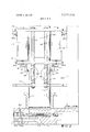
- FIG. 1 is a transverse vertical section of one form of the invention wherein a power ram moves against the end of a thermoplastic member wholly within the well.
- FIG. 2 is a transverse vertical section of another form of this invention wherein the thermoplastic member extends beyond the opening of the well and is engaged on its sides by a pair of downwardly pressing, power-actuated members.
- FIG. 2A is similar to FIG. 2 but with the pressure means engaging the thermoplastic member.
- FIG. 3 is a perspective view of a cement gun made in accordance with this invention, in closed position.
- FIG. 4 is a cross section along lines 44 of FIG. 3.
- FIG. 5 is a perspective view of the cement gun in open, loading position.
- open end well 12 is formed by an inner heating metal block 13 having a cavity and outer, hollow, non-heat-conductive cylinder 11.
- Block 13 has a bottom well orifice 140 leading to an outlet channel 14 ter-- minating at an exit port 14b.
- the exit port 14b contains a valve comprising a ball 31, a light stainless steel spring 32 and a spring-retaining strip 33.
- the valve is normally open unless pressure is applied by a metering pump 34 which has a delivery valve 35 and port 350.
- a transverse electrical heating element 21 is provided which extends adjacent the bottom of the well 12.
- a further electrical heating element 22 is provided which extends through the block 13 so as to provide suf- .-ficient heating means for the orifice of the welland the outlet.
- a sealing ring 19 typically made of an inert resilient material such as Teflon which is required if granules are used instead of a block.
- Ram 18 of piston 17 operated pneumatically in an upper air cylinder 15 is fitted to slide in well 12 and be sealed by ring 19.
- thermoplastic cement cylinder 20 is being continuously pushed downward by ram 18 so as to cause molten thermoplastic material 20a in the bottom of the well to be pushed out at port 14b when valve 30 is open.
- the entire charge of thermoplastic cement is shown contained within the well 12 but can extend outward as one or more abutting blocks.
- the electrical heating elements 21 and 22 are connected to a source of power (not illustrated) through conventional means (not illustrated) for controlling the amount of heat dispersed.
- the amount of heat is-so selected that the thermoplastic material in the bottom portion of the well is in 'a molten flowable condition.
- Flow control is achieved by the combination of continued ram pressure and control of pump 34.
- the device can thus be controlled so as to be either continuous or intermittent in its action. Since air cylinders and their controls and other power means for moving a ram are generally well understood, such details are not illustrated.
- an open end well 112 comprising a similar non-heat-conducting cylinder 111 and a metal heating block 213 containing electrical heating elements 221 and 222, bottom orifice 114a, channel 114 and exit port 114b.
- An externally controllable shut off valve 220 is provided at the exit port 11412.
- the means for applying downward pressure are different in this embodiment than that illustrated in FIG. I.
- thermoplastic members 120 and 120' extend a considerable distance above the open end of the well.
- a support 150 holdsa frame comprising an upper horizontal plate 140, a lower horizontal plate 142 and vertical rods 121 and 124 connected between the two plates.
- Anchored vertically to plate 140 are two air cylinders 115 and 130 spaced directly opposite one another on either side of the thermoplastic member and supplied by air lines 1l5b and 1 f 1301;.
- the piston rods of cylinders 115a and a extend through a horizontal plate 141 which is movable on rods 121 and 124 against springs 122 and 125.
- movable plate 141 Attached to movable plate 141 are depending arms 118 and 138 which, in turn, pivotally support Z-shaped members 117 and 132 on pins 116 and 131. Actuation of the piston rods 115a and 130 a cause them to engage with the Z-shaped members 117 and 132, so that the engaging portions thereof 119 and 134 bite into the thermoplastic member 120. Further downward motion of the piston rods 115a and 130a thus apply" downward pressure on the thermoplastic block 120.
- thermoplastic cement as, for example, a shoe-heel-attaching machine or a machine for applying thermoplastic cement in selected quantities to desired surfaces. While ram pressure and melt temperatures would depend on the material used and the feed required, we have generally observed that a continuous ram pressure in the range of about 20 to 80 pounds per square inch is useful with thermoplastic materials compounded from polyester or polyamide resins.
- the invention can be used in the form of a cement gun.
- the illustrated air-pressure cement gun embodiment of this invention comprises a supporting or handle portion 68 on which is mounted a heating block 39 having a cylindrical hollow inner portion 39a and an abutting hollow cylindrical insulating portion 100 which has a hollow portion 1000.
- the hollow portions 39a and 1000 register with one another to form the well which receives the fitted block of thermoplastic cement.
- the outer end of the cylindrical insulating sleeve 100 opens into hollow cylinder 51, which is provided with piston 52 threaded onto piston rod 53.
- Piston rod 53 also contains the air supply conduit for the cylinder connected through slide valve 54 to air hose 45.
- the cylinder piston assembly 51-52 is arranged to be pivotable on the end block of the well and is held in alignment with the well by latch 57.
- Heating block 39 has an outlet portion 39b opening into a conduit 56a in tubular nozzle 56. Spaced within the conduit 56a is a needle valve 6 actuable by a portion 50 connected to a spacer 115 and return spring 60. Actuation of the trigger 43 operates the valve 5.
- Operation of the trigger 43 also serves by means of spring mount 56a to vary the pressure in air valve 55. Air from air supply 71 enters valve 55 which is preset for constant minimum pressure and thence exits through hose 45 through slide valve 54 to cylinder 51. Accordingly, when the trigger is pulled back, it not only opens the orifice of the needle valve 56 but also allows more air pressure to go from air valve 55 into cylinder in this manner, actuation of the trigger both adds more pressure to the back of the thermoplastic block, as well as opening needle valve 56. Thus, pulling back on the trigger 43 controls the rate of flow of molten thermoplastic material out of the orifice 25 of the nozzle 56.
- the heating block 3% is provided with heating elements 62 and is typically made of aluminum or similar sturdy metal. Insulating sleeve 100 with is' tightly joined to the heating block 39 with O-ring 63 is typically made of a formable material such as impregnated fiberglass or transite.
- the piston 52 has an O-ring 52a for sealing with the cylinder 51. Piston 52 also has an orifice which accommodates an adjustable screw 52b which provides an air leak from the back of the piston to the end of the thermoplastic block.
- Such cooling is normally not required, but may be desirable where the gun is very small or the surrounding environment so hot that its air, which normally keeps sleeve 100 cool, is insufficiently cool to keep the end of the thermoplastic block in solid condition.
- thermometer 72 and thermostat 73 are provided to assist the operator in controlling desired molten cement temperature.
- Frame 65 serves as a heat shield.
- the latch 57 is released, and the hinged upper piston cylinder assembly 5l52 is moved away, thus exposing the interior 39a-l00a of the well and the interior of the cylinder 51.
- a block of thermoplastic cement 200 is inserted into the well and another block 201 into the cylinder.
- the slide valve 54 is off so that there is no pressure on piston 52.
- the cylinder is locked onto the well frame by means ofthe latch 57 and slide valve 54 is actuated, thus applying the predetermined constant pressure to the back of thermoplastic member 201 which moves against thermoplastic member 200.
- the latch 57 is released, and the hinged upper piston cylinder assembly 5l52 is moved away, thus exposing the interior 39a-l00a of the well and the interior of the cylinder 51.
- a block of thermoplastic cement 200 is inserted into the well and another block 201 into the cylinder.
- the slide valve 54 is off so that there is no pressure on piston 52.
- the cylinder is locked onto the well frame by means ofthe latch 57 and slide valve 54 is
- thermoplastic member only molten portion of the thermoplastic member will be that within the heating block and slightly above as indicated in FIG. 4. Such portion is kept constantly molten and is under continuous pressure.
- thermoplastic material comprising:
- a well adapted to receive a fitted member of cross section substantially identical to the cross section of the interior of the well and made of normallysolid thermoplastic material, said well being defined by registering cavities in abutting outer and inner sections, said outer section having an opening through which said thermoplastic member is loaded into said well; said inner section having a discharge orifice;
- said apparatus being characterized in that said constant reservoir of molten thermoplastic material is sealed by said solid thermoplastic material, and is under pressure so that opening of said valve means permits instantaneous outward flow of said molten thermoplastic material.
- said power means comprises fluid pressure means, said valve is actuable by a trigger and the movement of said trigger varies the amount of fluid pressure applied to the end of said thermoplastic member.
- said power means comprises air pressure means, said valve is actuableby a trigger and the movement of said trigger varies the amount of air pressure applied to the end of said thermoplastic member.
- said air pressure means includes an air pressure cylinder assembly pivotably mounted over the loading opening of said well so that it can be moved aside for insertion of a thermoplastic member, means being provided to hold said assembly in alignment withsaid well in closed position.
- said power means includes a substantially fitted ram movable against the end of said thermoplastic member within the well.
- thermoplastic meniber is inserted into the well and a second thermoplastic member into the cylinder assembly.
Abstract
THERMOPLASTIC RESINS ARE FED TO A DESIRED LOCATION BY AN APPARATUS HAVING A WELL WITH A HEATED INNER SECTION, PROVIDED WITH A DISCHARGE ORIFICE, AND AN UNHEATED OUTER SECTION. A FITTED, NORMALLY SOLID MEMBER OF THERMOPLASTIC MATERIAL IS PLACED IN THE WELL WHEREUPON ONLY ITS BOTTOM PORTION BECOMES MOLTEN. CONTINUOUS FLUID PRESSURE IS APPLIED ON THE
EXPOSED SOLID END OF THRMOPLASTIC MATERIAL AND IN CONJUNCTION WITH AN EXTERNALLY CONTROLLED VALVE PROVIDES CONTROLLABLE FEED, YET PROTECTS THE THERMOPLASTIC MATERIAL FROM OXIDATIVE DEGRADATION. ONE EMBODIMENT OF THE INVENTION COMPRISES A PORTABLE CEMENT GUN.
EXPOSED SOLID END OF THRMOPLASTIC MATERIAL AND IN CONJUNCTION WITH AN EXTERNALLY CONTROLLED VALVE PROVIDES CONTROLLABLE FEED, YET PROTECTS THE THERMOPLASTIC MATERIAL FROM OXIDATIVE DEGRADATION. ONE EMBODIMENT OF THE INVENTION COMPRISES A PORTABLE CEMENT GUN.
Description
i United States Patent Inventors Appl. No.
Filed Patented Assignee George Schultz Newton;
Michael Dziki, Dorchester, Mass.
July 29, 1969 June 28, 1971 industrial Shoe Machinery Roxbury, Mass.
Continuation-impart of application Ser. No. 712,224, Mar. 1 l, 1965, now abandoned.
- APPARATUS FOR DISPENSING THERMOPLASTIC MATERIAL 11 Claims, 6 Drawing Figs.
15.8. CI 222/146HE Int. Cl B67d 5/62 Field of Search 222/146, 386. l46(HE) [56] References Cited UNITED STATES PATENTS 2,Sl8,748 8/1950 Breer et al. (222/l46HE) 3,228,566 1/1966 Knox 222/146 3,285,475 11/1966 Phillips 222/146 Primary Examiner- Stanley H, Tollberg Attorney-Joseph Zallen ABSTRACT: Thermoplastic resins are fed to a desired location by an apparatus having a well with a heated inner section, provided with a discharge orifice, and an unheated outer section. A fitted, normally solid member of thermoplastic material is placed in the well whereupon only its bottom portion becomes molten. Continuous fluid pressure is applied on the exposed solid end of thermoplastic material and in conjunction with an externally controlled valve provides controllable feed, yet protects the thermoplastic material from oxidative degradation. One embodiment of the invention comprises a portable cement gun.
APPARATUS FOR DISPENSING THERMOPLASTIC MATERIAL This is a continuation-in-part of our copending application Ser. No. 7l2,224, filed Mar. ll, 1968, now abandoned.
BACKGROUND OF INVENTION Thermoplastic cements are used in many manufacturing procedures, as for 'examples, the assembly of various components of a shoe or in packaging. However, devices which have been previously described for dispensing such materials suffer from one or more disadvantages resulting from clogging and oxidation of the cement. This problem is particularly accentuated in the case of polyester and polyamide thermoplastic cementswhich are typically supplied as cylindrical blocks and melt at a temperature in the range of approximately 250 F.600B F.
SUMMARY OF INVENTION The invention in its broad sense comprises providing a well heated only in its inner section and adapted to receive a fitted block of normally solid thermoplastic material such as cement. An orifice is provided in the inner section of the well which opens into conduit means leading to an exit port. An externally controllable shutoff valve means is provided in the conduit. Power means, as for example, fluid pressure means, are supplied for continuously applying pressure to the exposed portion of the block of thermoplastic cement.
The apparatus is so arranged that sufficient heat is applied only in the inner section of the well and the exit conduit to melt the adjacent portion of the thermoplastic block and'keep it molten. However, the heat is so regulated, as for example,
I by making the walls of the outer section out of non-heat-conductive material, that the portion of the thermoplastic block adjacent the outer section of the well is kept in a solid state.
In one form of this invention, the thermoplastic block does not extend beyond the open end of the well. The fitted ram of a power cylinder slides within the well and is movableagainst the end of the block.
In a second form of this invention, the block of thermoplastic material can extend beyond the open end of the well. In this case the power ram does not move into the well but acts on the block of thermoplastic material which extends into the cylinder. Instead of a single block, a pair or more of abutting blocks can be used, which make it easier toload, as in the case of a cement gun.
In a third form of this invention the block or series of abutting blocks extend beyond the open end of the well and I are pressed downward by pressure means engaging the side of an exposed portion of the block or blocks.
' We have found that by use of this invention we are able to provide a desired rate of uniform, variable or intermittent cement feed over extremely long periods of time without any clogging and without any charring. We have also found that thermoplastic cement can be stored in the apparatus of our invention in either heated condition or unheated condition for very long periods of time without deterioration, charring or clogging.
BRIEF DESCRIPTION OF DRAWINGS FIG. 1 is a transverse vertical section of one form of the invention wherein a power ram moves against the end of a thermoplastic member wholly within the well.
FIG. 2 is a transverse vertical section of another form of this invention wherein the thermoplastic member extends beyond the opening of the well and is engaged on its sides by a pair of downwardly pressing, power-actuated members.
FIG. 2A is similar to FIG. 2 but with the pressure means engaging the thermoplastic member.
FIG. 3 is a perspective view of a cement gun made in accordance with this invention, in closed position.
FIG. 4 is a cross section along lines 44 of FIG. 3.
FIG. 5 is a perspective view of the cement gun in open, loading position.
SPECIFIC EXAMPLE OF INVENTION In the embodiment illustrated in FIG. 1, open end well 12 is formed by an inner heating metal block 13 having a cavity and outer, hollow, non-heat-conductive cylinder 11. Block 13 has a bottom well orifice 140 leading to an outlet channel 14 ter-- minating at an exit port 14b. The exit port 14b contains a valve comprising a ball 31, a light stainless steel spring 32 and a spring-retaining strip 33. The valve is normally open unless pressure is applied by a metering pump 34 which has a delivery valve 35 and port 350. A transverse electrical heating element 21 is provided which extends adjacent the bottom of the well 12. A further electrical heating element 22 is provided which extends through the block 13 so as to provide suf- .-ficient heating means for the orifice of the welland the outlet.
channel.
On the top of the inner surface of the well 12 is a sealing ring 19 typically made of an inert resilient material such as Teflon which is required if granules are used instead of a block. Ram 18 of piston 17 operated pneumatically in an upper air cylinder 15 is fitted to slide in well 12 and be sealed by ring 19.
In this version, a fitted thermoplastic cement cylinder 20 is being continuously pushed downward by ram 18 so as to cause molten thermoplastic material 20a in the bottom of the well to be pushed out at port 14b when valve 30 is open. The entire charge of thermoplastic cement is shown contained within the well 12 but can extend outward as one or more abutting blocks.
The electrical heating elements 21 and 22 are connected to a source of power (not illustrated) through conventional means (not illustrated) for controlling the amount of heat dispersed. The amount of heat is-so selected that the thermoplastic material in the bottom portion of the well is in 'a molten flowable condition. Flow control is achieved by the combination of continued ram pressure and control of pump 34. The device can thus be controlled so as to be either continuous or intermittent in its action. Since air cylinders and their controls and other power means for moving a ram are generally well understood, such details are not illustrated.
In the embodiment illustrated in FIGS. 2 and 2A, there is an open end well 112 comprising a similar non-heat-conducting cylinder 111 and a metal heating block 213 containing electrical heating elements 221 and 222, bottom orifice 114a, channel 114 and exit port 114b. An externally controllable shut off valve 220 is provided at the exit port 11412. The means for applying downward pressure are different in this embodiment than that illustrated in FIG. I.
In FIGS. 2 and 2A abutting thermoplastic members 120 and 120' extend a considerable distance above the open end of the well. A support 150 holdsa frame comprising an upper horizontal plate 140, a lower horizontal plate 142 and vertical rods 121 and 124 connected between the two plates.
Anchored vertically to plate 140 are two air cylinders 115 and 130 spaced directly opposite one another on either side of the thermoplastic member and supplied by air lines 1l5b and 1 f 1301;. The piston rods of cylinders 115a and a extend through a horizontal plate 141 which is movable on rods 121 and 124 against springs 122 and 125.
Attached to movable plate 141 are depending arms 118 and 138 which, in turn, pivotally support Z-shaped members 117 and 132 on pins 116 and 131. Actuation of the piston rods 115a and 130 a cause them to engage with the Z-shaped members 117 and 132, so that the engaging portions thereof 119 and 134 bite into the thermoplastic member 120. Further downward motion of the piston rods 115a and 130a thus apply" downward pressure on the thermoplastic block 120. When block 120 has been moved so that its end is near the well opening, retraction of the piston rods 115a and 130a frees the engaging members 117 and I32 from the block, thus per-- mitting the compressed springs 122 and 123 to raise the movable plate 141 to its original position, thus positioning the Z- shaped members so as to now be engageable with a succeeding thermoplastic block 120' which had been stored on the first thermoplastic block 120.
The apparatus of these examples of the invention can be incorporated or attached to a machine which will utilize the thermoplastic cement, as, for example, a shoe-heel-attaching machine or a machine for applying thermoplastic cement in selected quantities to desired surfaces. While ram pressure and melt temperatures would depend on the material used and the feed required, we have generally observed that a continuous ram pressure in the range of about 20 to 80 pounds per square inch is useful with thermoplastic materials compounded from polyester or polyamide resins.
In addition to fixed cement-dispensing installations, the invention can be used in the form of a cement gun. As shown in FIGS. 3-5, the illustrated air-pressure cement gun embodiment of this invention comprises a supporting or handle portion 68 on which is mounted a heating block 39 having a cylindrical hollow inner portion 39a and an abutting hollow cylindrical insulating portion 100 which has a hollow portion 1000. The hollow portions 39a and 1000 register with one another to form the well which receives the fitted block of thermoplastic cement.
The outer end of the cylindrical insulating sleeve 100 opens into hollow cylinder 51, which is provided with piston 52 threaded onto piston rod 53. Piston rod 53 also contains the air supply conduit for the cylinder connected through slide valve 54 to air hose 45. The cylinder piston assembly 51-52 is arranged to be pivotable on the end block of the well and is held in alignment with the well by latch 57.
Operation of the trigger 43 also serves by means of spring mount 56a to vary the pressure in air valve 55. Air from air supply 71 enters valve 55 which is preset for constant minimum pressure and thence exits through hose 45 through slide valve 54 to cylinder 51. Accordingly, when the trigger is pulled back, it not only opens the orifice of the needle valve 56 but also allows more air pressure to go from air valve 55 into cylinder in this manner, actuation of the trigger both adds more pressure to the back of the thermoplastic block, as well as opening needle valve 56. Thus, pulling back on the trigger 43 controls the rate of flow of molten thermoplastic material out of the orifice 25 of the nozzle 56.
The heating block 3% is provided with heating elements 62 and is typically made of aluminum or similar sturdy metal. Insulating sleeve 100 with is' tightly joined to the heating block 39 with O-ring 63 is typically made of a formable material such as impregnated fiberglass or transite. The piston 52 has an O-ring 52a for sealing with the cylinder 51. Piston 52 also has an orifice which accommodates an adjustable screw 52b which provides an air leak from the back of the piston to the end of the thermoplastic block. Such cooling is normally not required, but may be desirable where the gun is very small or the surrounding environment so hot that its air, which normally keeps sleeve 100 cool, is insufficiently cool to keep the end of the thermoplastic block in solid condition.
A thermometer 72 and thermostat 73 are provided to assist the operator in controlling desired molten cement temperature. Frame 65 serves as a heat shield.
In operation, the latch 57 is released, and the hinged upper piston cylinder assembly 5l52 is moved away, thus exposing the interior 39a-l00a of the well and the interior of the cylinder 51. A block of thermoplastic cement 200 is inserted into the well and another block 201 into the cylinder. At this particular moment, the slide valve 54 is off so that there is no pressure on piston 52. As soon as the blocks are loaded, the cylinder is locked onto the well frame by means ofthe latch 57 and slide valve 54 is actuated, thus applying the predetermined constant pressure to the back of thermoplastic member 201 which moves against thermoplastic member 200. Inasmuch as only the lower portion of the well, 39a, is being heated and since the upper portion of the well 100a has nonheat-conductive walls and is exposed to the air on its sides, the
only molten portion of the thermoplastic member will be that within the heating block and slightly above as indicated in FIG. 4. Such portion is kept constantly molten and is under continuous pressure.
We claim:
1. An apparatus for dispensing thermoplastic material comprising:
a. a well adapted to receive a fitted member of cross section substantially identical to the cross section of the interior of the well and made of normallysolid thermoplastic material, said well being defined by registering cavities in abutting outer and inner sections, said outer section having an opening through which said thermoplastic member is loaded into said well; said inner section having a discharge orifice;
b. means for heating said inner section to provide therein a constant reservoir of molten thermoplastic material within said inner cavity, the walls of said outer section being sufficiently cooler than the walls of said inner section so that any molten material solidifies before reaching said opening and the portion of said thermoplastic member near or exterior to the loading opening remains solid at all times;
c. conduit means in said inner well section leading from said orifice to an exit port;
d. externally controllable valve means in said conduit;
e. power means for applying pressure against the outer end of such a thermoplastic member in said well whether or not said valve means is closed or open;
said apparatus being characterized in that said constant reservoir of molten thermoplastic material is sealed by said solid thermoplastic material, and is under pressure so that opening of said valve means permits instantaneous outward flow of said molten thermoplastic material.
2. The apparatus of claim 1 wherein the walls of said outer well section are substantially less heat conductive than the walls of said inner well section.
3. The apparatus of claim 1 wherein said outer well section is made of heat-insulating material and said inner well section is a metal block having electrical heating means inserted therein.
4. The apparatus of claim 1 wherein said power means comprises fluid pressure means, said valve is actuable by a trigger and the movement of said trigger varies the amount of fluid pressure applied to the end of said thermoplastic member.
5. The apparatus of claim 4 wherein said power means comprises air pressure means, said valve is actuableby a trigger and the movement of said trigger varies the amount of air pressure applied to the end of said thermoplastic member.
6. The apparatus of claim 4 wherein said outer well section is an insulating sleeve, said inner well section is a metal block with electrical heating means inserted therein, said power means comprises air pressure means, said valve is actuable by a trigger and movement of said trigger varies the amount of fluid pressure applied to such a thermoplastic member inserted in said well.
7. The apparatus of claim 5 wherein said air pressure means includes an air pressure cylinder assembly pivotably mounted over the loading opening of said well so that it can be moved aside for insertion of a thermoplastic member, means being provided to hold said assembly in alignment withsaid well in closed position.
8. The apparatus of claim 1 wherein said power means includes a substantially fitted ram movable against the end of said thermoplastic member within the well.
9. The apparatus of claim 1 wherein said well is adapted to receive a single thermoplastic member or abutting members extending beyond the open end of the well.
10. The apparatus of claim 9 wherein said power means in cludes a pressure means engageable outside the well with the exposed portion of the thermoplastic member.
11. The apparatus of claim 7 wherein one thermoplastic meniber is inserted into the well and a second thermoplastic member into the cylinder assembly.
Applications Claiming Priority (1)
| Application Number | Priority Date | Filing Date | Title |
|---|---|---|---|
| US84781769A | 1969-07-29 | 1969-07-29 |
Publications (1)
| Publication Number | Publication Date |
|---|---|
| US3587930A true US3587930A (en) | 1971-06-28 |
Family
ID=25301581
Family Applications (1)
| Application Number | Title | Priority Date | Filing Date |
|---|---|---|---|
| US847817A Expired - Lifetime US3587930A (en) | 1969-07-29 | 1969-07-29 | Apparatus for dispensing thermoplastic material |
Country Status (16)
| Country | Link |
|---|---|
| US (1) | US3587930A (en) |
| JP (1) | JPS498498B1 (en) |
| AT (1) | AT307927B (en) |
| BE (1) | BE753948A (en) |
| CH (1) | CH522444A (en) |
| DE (1) | DE2036423A1 (en) |
| DK (1) | DK129217B (en) |
| ES (1) | ES382242A1 (en) |
| FR (1) | FR2055287A5 (en) |
| GB (1) | GB1314614A (en) |
| LU (1) | LU61420A1 (en) |
| MC (1) | MC854A1 (en) |
| NL (1) | NL7011181A (en) |
| NO (2) | NO129839B (en) |
| SE (2) | SE386600B (en) |
| ZA (1) | ZA704656B (en) |
Cited By (25)
| Publication number | Priority date | Publication date | Assignee | Title |
|---|---|---|---|---|
| US3773069A (en) * | 1971-02-03 | 1973-11-20 | Usm Corp | Apparatus for dispensing heat softenable adhesive initially in granule form |
| US3818930A (en) * | 1973-04-20 | 1974-06-25 | Nordson Corp | Control system for an adhesive gun |
| US3868046A (en) * | 1970-12-03 | 1975-02-25 | Cities Service Co | Extruder |
| US3877610A (en) * | 1974-02-01 | 1975-04-15 | Ornsteen Chemicals & Textiles | Hot melt cartridge adhesive gun |
| US3951308A (en) * | 1973-12-07 | 1976-04-20 | Sale Tilney Ag | Apparatus for dispensing adhesive material |
| US3960296A (en) * | 1974-09-09 | 1976-06-01 | Nordson Corporation | Thermoplastic dispenser |
| US3971492A (en) * | 1974-09-30 | 1976-07-27 | Lockwood Technical, Inc. | Hot melt applicator gun |
| US3973697A (en) * | 1972-11-16 | 1976-08-10 | Nordson Corporation | Adhesive gun |
| US4026440A (en) * | 1974-08-26 | 1977-05-31 | Nordson Corporation | Adhesive gun |
| US4144913A (en) * | 1977-01-26 | 1979-03-20 | Nordson Corporation | Hot melt adhesive dispensing system of the hand held gun type |
| US4303108A (en) * | 1977-01-26 | 1981-12-01 | Nordson Corporation | Hot melt adhesive dispensing system of the hand held gun type |
| US4457457A (en) * | 1982-01-27 | 1984-07-03 | Minnesota Mining And Manufacturing Company | Apparatus for dispensing thermoplastic material |
| FR2573677A1 (en) * | 1984-11-24 | 1986-05-30 | Bosch Gmbh Robert | Hot adhesive application gun |
| US20040074927A1 (en) * | 2002-10-18 | 2004-04-22 | Lafond Luc Marcel | Portable gas powered fluid dispenser |
| US20040226968A1 (en) * | 2003-03-04 | 2004-11-18 | Lafond Luc Marcel | Nozzle for dispensable viscous materials |
| US6935541B1 (en) | 2004-08-17 | 2005-08-30 | Black & Decker Inc. | Caulk gun pressurizing system |
| US20050230433A1 (en) * | 2004-04-20 | 2005-10-20 | Campbell David C | Pressure release connection and pneumatic dispensing device |
| US20050230434A1 (en) * | 2004-04-20 | 2005-10-20 | Campbell David C | Dispensing device using multiple gas cartridges |
| US20050247740A1 (en) * | 2004-05-07 | 2005-11-10 | Daniel Puzio | Pneumatic dispensing device with frangible seal breaker and method |
| US20060027604A1 (en) * | 2004-08-05 | 2006-02-09 | Daniel Puzio | Pressure regulator and dispensing device |
| US20060043119A1 (en) * | 2004-08-25 | 2006-03-02 | Gibbons Louis A | Dispensing device with rack and pinion drive for nozzle valve |
| US20060043120A1 (en) * | 2004-08-27 | 2006-03-02 | Campbell David C | Cordless DC caulk gun |
| US20090065532A1 (en) * | 2004-11-05 | 2009-03-12 | Luc Marcel Lafond | Dispensing device with secondary reservoir |
| US20180273804A1 (en) * | 2014-11-20 | 2018-09-27 | Zephyros, Inc. | Application of adhesives |
| US10342588B2 (en) | 2015-10-09 | 2019-07-09 | Heraues Medical Gmbh | Paste application device for mixing a paste |
Families Citing this family (4)
| Publication number | Priority date | Publication date | Assignee | Title |
|---|---|---|---|---|
| DE2336454C2 (en) * | 1973-07-18 | 1983-07-21 | Günter 3070 Nienburg Wehrmann | Hand-held device for applying hot melt adhesives |
| LU70914A1 (en) * | 1973-09-18 | 1975-02-24 | ||
| GB2162902A (en) * | 1984-07-21 | 1986-02-12 | Nippon Tansan Gas Co Ltd | Viscous agent injecting instrument |
| GB2334014B (en) * | 1998-02-03 | 2002-09-11 | Hare Francis O' | Depilatory Wax Dispenser |
-
1969
- 1969-07-29 US US847817A patent/US3587930A/en not_active Expired - Lifetime
-
1970
- 1970-07-06 ZA ZA704656A patent/ZA704656B/en unknown
- 1970-07-16 MC MC907A patent/MC854A1/en unknown
- 1970-07-17 FR FR7026449A patent/FR2055287A5/fr not_active Expired
- 1970-07-20 GB GB3502170A patent/GB1314614A/en not_active Expired
- 1970-07-20 SE SE7010011A patent/SE386600B/en unknown
- 1970-07-22 DE DE19702036423 patent/DE2036423A1/en active Pending
- 1970-07-24 CH CH1125070A patent/CH522444A/en not_active IP Right Cessation
- 1970-07-24 AT AT681770A patent/AT307927B/en not_active IP Right Cessation
- 1970-07-27 BE BE753948D patent/BE753948A/en unknown
- 1970-07-27 LU LU61420D patent/LU61420A1/xx unknown
- 1970-07-28 NO NO02920/70A patent/NO129839B/no unknown
- 1970-07-28 ES ES382242A patent/ES382242A1/en not_active Expired
- 1970-07-29 NL NL7011181A patent/NL7011181A/xx unknown
- 1970-07-29 DK DK392870AA patent/DK129217B/en unknown
- 1970-07-29 JP JP45066492A patent/JPS498498B1/ja active Pending
-
1973
- 1973-07-04 NO NO2736/73A patent/NO132026C/no unknown
-
1975
- 1975-01-08 SE SE7500182A patent/SE7500182L/xx unknown
Cited By (30)
| Publication number | Priority date | Publication date | Assignee | Title |
|---|---|---|---|---|
| US3868046A (en) * | 1970-12-03 | 1975-02-25 | Cities Service Co | Extruder |
| US3773069A (en) * | 1971-02-03 | 1973-11-20 | Usm Corp | Apparatus for dispensing heat softenable adhesive initially in granule form |
| US3973697A (en) * | 1972-11-16 | 1976-08-10 | Nordson Corporation | Adhesive gun |
| US3818930A (en) * | 1973-04-20 | 1974-06-25 | Nordson Corp | Control system for an adhesive gun |
| US3951308A (en) * | 1973-12-07 | 1976-04-20 | Sale Tilney Ag | Apparatus for dispensing adhesive material |
| US3877610A (en) * | 1974-02-01 | 1975-04-15 | Ornsteen Chemicals & Textiles | Hot melt cartridge adhesive gun |
| US4026440A (en) * | 1974-08-26 | 1977-05-31 | Nordson Corporation | Adhesive gun |
| US3960296A (en) * | 1974-09-09 | 1976-06-01 | Nordson Corporation | Thermoplastic dispenser |
| US3971492A (en) * | 1974-09-30 | 1976-07-27 | Lockwood Technical, Inc. | Hot melt applicator gun |
| US4144913A (en) * | 1977-01-26 | 1979-03-20 | Nordson Corporation | Hot melt adhesive dispensing system of the hand held gun type |
| US4303108A (en) * | 1977-01-26 | 1981-12-01 | Nordson Corporation | Hot melt adhesive dispensing system of the hand held gun type |
| US4457457A (en) * | 1982-01-27 | 1984-07-03 | Minnesota Mining And Manufacturing Company | Apparatus for dispensing thermoplastic material |
| FR2573677A1 (en) * | 1984-11-24 | 1986-05-30 | Bosch Gmbh Robert | Hot adhesive application gun |
| US20040074927A1 (en) * | 2002-10-18 | 2004-04-22 | Lafond Luc Marcel | Portable gas powered fluid dispenser |
| US7163130B2 (en) | 2002-10-18 | 2007-01-16 | Luc Marcel Lafond | Portable gas powered fluid dispenser |
| US20040226968A1 (en) * | 2003-03-04 | 2004-11-18 | Lafond Luc Marcel | Nozzle for dispensable viscous materials |
| US20050230433A1 (en) * | 2004-04-20 | 2005-10-20 | Campbell David C | Pressure release connection and pneumatic dispensing device |
| US20050230434A1 (en) * | 2004-04-20 | 2005-10-20 | Campbell David C | Dispensing device using multiple gas cartridges |
| US7275663B2 (en) | 2004-04-20 | 2007-10-02 | Black & Decker Inc. | Dispensing device using multiple gas cartridges |
| US7188753B2 (en) | 2004-04-20 | 2007-03-13 | Black & Decker Inc. | Pressure release connection and pneumatic dispensing device |
| US20050247740A1 (en) * | 2004-05-07 | 2005-11-10 | Daniel Puzio | Pneumatic dispensing device with frangible seal breaker and method |
| US20060027604A1 (en) * | 2004-08-05 | 2006-02-09 | Daniel Puzio | Pressure regulator and dispensing device |
| US6935541B1 (en) | 2004-08-17 | 2005-08-30 | Black & Decker Inc. | Caulk gun pressurizing system |
| US7185792B2 (en) | 2004-08-25 | 2007-03-06 | Black & Decker Inc. | Dispensing device with rack and pinion drive for nozzle valve |
| US20060043119A1 (en) * | 2004-08-25 | 2006-03-02 | Gibbons Louis A | Dispensing device with rack and pinion drive for nozzle valve |
| US20060043120A1 (en) * | 2004-08-27 | 2006-03-02 | Campbell David C | Cordless DC caulk gun |
| US7261220B2 (en) | 2004-08-27 | 2007-08-28 | Black & Decker Inc. | Cordless DC caulk gun |
| US20090065532A1 (en) * | 2004-11-05 | 2009-03-12 | Luc Marcel Lafond | Dispensing device with secondary reservoir |
| US20180273804A1 (en) * | 2014-11-20 | 2018-09-27 | Zephyros, Inc. | Application of adhesives |
| US10342588B2 (en) | 2015-10-09 | 2019-07-09 | Heraues Medical Gmbh | Paste application device for mixing a paste |
Also Published As
| Publication number | Publication date |
|---|---|
| NO132026B (en) | 1975-06-02 |
| SE386600B (en) | 1976-08-16 |
| JPS498498B1 (en) | 1974-02-26 |
| BE753948A (en) | 1971-01-27 |
| NL7011181A (en) | 1971-02-02 |
| ES382242A1 (en) | 1972-12-01 |
| SE7500182L (en) | 1975-01-08 |
| NO129839B (en) | 1974-06-04 |
| AT307927B (en) | 1973-06-12 |
| LU61420A1 (en) | 1970-09-28 |
| MC854A1 (en) | 1971-06-07 |
| GB1314614A (en) | 1973-04-26 |
| NO132026C (en) | 1975-09-10 |
| CH522444A (en) | 1972-06-30 |
| DE2036423A1 (en) | 1971-03-04 |
| ZA704656B (en) | 1972-02-23 |
| FR2055287A5 (en) | 1971-05-07 |
| DK129217C (en) | 1975-02-03 |
| DK129217B (en) | 1974-09-16 |
Similar Documents
| Publication | Publication Date | Title |
|---|---|---|
| US3587930A (en) | Apparatus for dispensing thermoplastic material | |
| US4033484A (en) | Hot melt cartridge adhesive gun | |
| CA1060855A (en) | Apparatus for feeding glue to a hot melt glue dispensing appliance | |
| US2567960A (en) | Plastic extrusion gun | |
| US3665158A (en) | Plastic extrusion device | |
| US3826224A (en) | Thermoplastic dispenser system having non-clogging melting zone | |
| US4804110A (en) | Apparatus, method and article for applying a melted adhesive | |
| US7703705B2 (en) | Apparatus and method for dispensing a mixture of a gas and a fluid material | |
| DE2030032C3 (en) | Device for supplying a consumer with molten thermoplastic material | |
| US20060188645A1 (en) | Deposition device having a thermal control system | |
| US7490735B2 (en) | Method and apparatus for dispensing a hot-melt adhesive | |
| US3743142A (en) | Adhesive extruders | |
| US3488244A (en) | Heat sealing apparatus | |
| US4096973A (en) | Portable sealant applicator | |
| US3408008A (en) | Apparatus for applying hot melt adhesives | |
| US3550815A (en) | Applicator for dispensing a molten material | |
| US4099653A (en) | Molten adhesive dispensing device | |
| CN110270478B (en) | No-drop hot melt glue gun | |
| US3543968A (en) | Gun for dispensing thermoplastic materials | |
| US5816452A (en) | Dispenser gun for viscous or semi-viscous products | |
| US3892339A (en) | Equipment for point by point application of an adhesive | |
| US3954206A (en) | Applicator for extruding molten thermoplastic material | |
| US3811405A (en) | Thermoplastic dispenser system | |
| US5197633A (en) | Material metering apparatus | |
| US2972670A (en) | Cement handling apparatus |