US3596055A - Method and apparatus for producing displays utilizing an electronic display system - Google Patents
Method and apparatus for producing displays utilizing an electronic display system Download PDFInfo
- Publication number
- US3596055A US3596055A US823128A US3596055DA US3596055A US 3596055 A US3596055 A US 3596055A US 823128 A US823128 A US 823128A US 3596055D A US3596055D A US 3596055DA US 3596055 A US3596055 A US 3596055A
- Authority
- US
- United States
- Prior art keywords
- thermal
- display medium
- display system
- bodies
- elements
- Prior art date
- Legal status (The legal status is an assumption and is not a legal conclusion. Google has not performed a legal analysis and makes no representation as to the accuracy of the status listed.)
- Expired - Lifetime
Links
Images


Classifications
-
- B—PERFORMING OPERATIONS; TRANSPORTING
- B41—PRINTING; LINING MACHINES; TYPEWRITERS; STAMPS
- B41M—PRINTING, DUPLICATING, MARKING, OR COPYING PROCESSES; COLOUR PRINTING
- B41M5/00—Duplicating or marking methods; Sheet materials for use therein
- B41M5/26—Thermography ; Marking by high energetic means, e.g. laser otherwise than by burning, and characterised by the material used
- B41M5/382—Contact thermal transfer or sublimation processes
- B41M5/38207—Contact thermal transfer or sublimation processes characterised by aspects not provided for in groups B41M5/385 - B41M5/395
-
- B—PERFORMING OPERATIONS; TRANSPORTING
- B41—PRINTING; LINING MACHINES; TYPEWRITERS; STAMPS
- B41J—TYPEWRITERS; SELECTIVE PRINTING MECHANISMS, i.e. MECHANISMS PRINTING OTHERWISE THAN FROM A FORME; CORRECTION OF TYPOGRAPHICAL ERRORS
- B41J2/00—Typewriters or selective printing mechanisms characterised by the printing or marking process for which they are designed
- B41J2/315—Typewriters or selective printing mechanisms characterised by the printing or marking process for which they are designed characterised by selective application of heat to a heat sensitive printing or impression-transfer material
- B41J2/32—Typewriters or selective printing mechanisms characterised by the printing or marking process for which they are designed characterised by selective application of heat to a heat sensitive printing or impression-transfer material using thermal heads
- B41J2/325—Typewriters or selective printing mechanisms characterised by the printing or marking process for which they are designed characterised by selective application of heat to a heat sensitive printing or impression-transfer material using thermal heads by selective transfer of ink from ink carrier, e.g. from ink ribbon or sheet
Definitions
- an energy or heat transferable coating such as carbon paper
- a display medium which preferably is nonsensitized, and selectively energizing certain mesas to form selective hotspots
- the heat produced thereby thermally transfers said transferable coating with the display medium, thereby to produce an information representation on the display medium.
- each of the mesas includes a diffused resistor in the collector circuit of a diffused transistor. Current through the collector resistor is controlled by a pulse applied to the base of the transistor, thus raising the mesa to an elevated temperature thereby causing a hotspot" to appear on the face of the mesas.
- the mesas may be selectively energized by a character generating logic circuit in a manner to specially reproduce the character which may be viewed by changing the color of a thermochromic material or by changing the color of a thermally sensitive paper disposed adjacent to the mesas or printheads.
- the color change (information representation) produced on the thermally sensitive display medium by the hotspot is not archival (permanent). Exposure to sunlight or normal aging, for example, causes the representation to fade.
- printhead temperatures between 175 C and 225 C are needed to cause an information representation to form on the display medium.
- the thermally sensitive paper which is in direct contact with the mesas of the printhead, not only subjects the printhead to wear, residue buildup from the thermal coating on the paper, and sticking, but also is more expensive than basic paper (nonsensitized paper).
- Another object of the invention is to provide a thermal display system which will produce an archival reproduction on a display medium.
- Another object of the invention is to provide a thermal display system which will produce an archival reproduction on a nonsensitized display medium.
- Still another object of the invention is to produce a thermal display system which requires lower printhead temperatures than are required to activate most thermochromic paper for producing an information representation on a display medium.
- Still another object of the invention is to provide a display system using a low cost display medium, such as a nonsensitized paper.
- FIG. I is an enlarged view ofan electronic printhead
- FIG. 2 is a schematic circuit diagram of a heater element of the thermal printhead of FIG. 1;
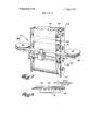
- FIG. 3 is an isometric view partially broken away of an electronic printhead and carriage assembly therefor usable in a thermal printer according to the present invention
- FIG. 4 is an enlarged front view of the electronic printhead assembly shown in FIG. 3;
- FIG. 5 is an isometric view of an electronic thermal printer utilizing the electronic printhead and carriage assembly shown in FIG. 3;
- FIG. 6 is a top view of the printhead, heat transferable material and display medium.
- FIGS. 7 and 8 illustrate another embodiment of the present invention.
- FIGS. l4 a thermal printhead of the type, for example, described and claimed in various aspects in copending US. Pat. application, Ser. No. 67l,82l, filed Sept. 29, 1967, entitled Integrated Heater Element Array and Drive Matrix and Method of Making Same," assigned to the assignee of the present application, is indicated generally by the reference numeral 10.
- the printhead 10 is composed of a 5 X 5 matrix of semiconductor mesas or bodies 12, which are thermally isolated from one another by airgaps, as best seen in FIG. 1, and which are bonded to a ceramic chip or substrate 0 14 by a thermally insulating epoxy layer 16.
- a transistor 18 and a resistor 20 see FIG.
- a buffer transistor 22 for each of the 25 mesas I2 is diffused into the face of semiconductor chip 24, generally within the area designated by the dotted outline 26 (see FIG. 4), the printhead circuits and the buffer circuits being interconnected by thin metallic film leads (not illustrated) on the surface of the semiconductor mesas 12 and the chip 24 adjacent the epoxy layer 16.
- the ceramic chip 14 is the bonded to a metallic heat sink 28.
- the leads from the bases of the buffer transistors 22 terminate around the periphery of the semiconductor chip 24, and are bonded to leads 30 on a printed circuit templet 32 mounted on the heat sink.
- the leads 30 on the printed circuit templet are soldered to the leads of a multilead strap 34 which, in turn, are interconnected to character generating logic circuits (not shown).
- the printhead assembly as illustrated in FIG. 3 may be utilized in a thermal printer such as the one illustrated in FIG. 5.
- FIG. 5 illustrates an electronic thermal printer utilizing the present invention and indicated by the reference numeral 40.
- Two end plates 42 and 44 provide the support for feeding the display medium 46, which can, for example, be either thermally sensitive paper or nonsensitive paper, from a large roll fed from spool 48.
- the electronic printhead and carriage therefor indicated generally by the reference numeral 28 (and shown in detail in FIG. 3) is secured to driving mechanism 49 which is slidably mounted on cylindrical rods 50 and a conventional stepping motor in mechanism 49 (not shown in detail) steps the carriage from left to right after the character print portion of the printing cycle, and upon completing the printout ofa line drives the printhead carriage back to the left-hand margin position.
- Supports 51 and 52 are connected to end plates 42 and 44, respectively.
- An energy or thermally transferable coating 54 (for example, a carbon composition such as a wax mixed with carbon particles or other suitable pigment) and support therefor 56 (see FIG. 6) is between the carriage 28 and the display medium 46.
- This coating 54 may be on a thin, flexible material 56, such as paper, or a plastic such as polyester (Mylar), polyethylene, polyimide (H-film), or the like, and is moved, for example, as a ribbon 56 past the carriage 28 by takeup reel 58 and feed reel 60 located on supports 51 and 52, respectively.
- the thermally transferable coating 54 and support material 56 may be a conventional carbon ribbon of the type, for example, used with conventional impact mechanical typewriters, by way of a further example.
- FIG. 6 illustrates the respective positions of the printhead 10 and mesas 12 with regard to the display medium 46, thermally transferable coating 54, and thin, flexible support material 56.
- the electronic carriage assembly 28 is successively stepped across the display medium 46 from left to right by a motor in mechanism 49.
- selective mesas 12 are energized, thereby producing hotspots at the surface of the mesas.
- the heat generated by the selected mesas passes through material 56 which, in turn, causes the thermally transferable coating 54 to transfer onto the display medium 46 which, as previously stated, may be sensitized or nonsensitized paper (see FIG. 6) passing in contact therewith. Accordingly, the heat from the selected mesas I2 is thermally coupled through material 56 to coating 54.
- This printing cycle is repeated until the printout for the particular line is completed, at which time the carriage assembly 28 is returned to the lefthand margin position, display medium 46 is advanced one line by advance means (not shown) and fed from spool 48, and the takeup reel 58 is appropriately advanced by means (not shown) to allow additional unused portion of the coating 54 to come into contact with the printhead 10.
- the temperature required of thermal printhead 10 to obtain an information representation on display medium 46 ranges between 100 C to 125 C. If a higher printhead temperature is required (in order to obtain faster speed of operation of printer 40), such as between 175 C and 225 C, it is either desirable to insure that the service temperature of the material 56 (shown in FIGS. 5 and 6) exceeds the operating temperature of the printhead, or if the support material 56 has a service temperature less than the operating temperature of the printhead 10, to interpose a high temperature insulator between the thermal printhead l0 and the support material 56 to insure that the softened support material 56 does not adhere to printhead 10, such as is shown in FIG. 7.
- FIG. 7 illustrates an electronic thermal printer indicated generally by the reference numeral 70.
- the display medium 46 which may be plain paper, is fed from spool 74 and supported by roller 75.
- the thermally transferable coating 54 is on support material 56 (see FIG. 8) and is distributed by spool 72 over reel 78. Similar to the embodiment shown in FIG. 5, the heat transferable coating may be a carbonlike composition and the support material may be paper or plastic, such as polyethylene (which has a service temperature of approximately 125 C).
- This temperature insulating material is shown in FIG. 7 as a ribbon interconnected between feed reel 82 and takeup reel 84.
- This high temperature insulator material could be a high temperature plastic, such as polyimide, which has a service temperature of 400 C, which is well in excess of the 175 C to 225 C printhead temperature range beforementioned.
- printer 70 Operation of printer 70 is similar to that described with regard to FIG. 5, with the addition that printhead 10 may operate in the range of 175 C to 225 C and the heat generated by the thermal mesas or bodies 12 on printhead 10 is thermally transferred through both the temperature insulator material 80 and the support material 56 to form an information representation on display medium 46.
- support material 56 and energy transferable coating 54 are shown in a ribbon format and in sheets supplied from different spools, other configurations are possible, such as the support material 56 and transferable coating 54 and the display medium 46 could be supplied from the same spool or physically attached.
- the 5 X 5 array of mesas is given herein as an example only since any number and shape of the array may be chosen, depending upon the character of the information desired to be displayed on the display medium.
- thermal printhead having thermal elements therein, a display medium, a support material between said elements and said display medium, a thermally transferable coating on said material adjacent to said display medium, and a high temperature insulator material interposed between said thermal ele- 0 ments and said support material.
- a thermal display system according to claim 1 wherein said display medium is nonsensitive paper.
- thermo display system according to claim 3 wherein said plastic is polyimide.
- a thermal display system comprising in combination a substrate, an array of semiconductor bodies upon one surface of said substrate, said array being so arranged that select ones of said bodies define a form of information representation, heater elements within each of said bodies, means for selectively energizing said heater elements thereby to heat said select ones ofsaid bodies, a display medium, a thermally transferable coating between said semiconductor bodies and said display medium and an insulating material interposed between said thermally transferable coating and said semiconductor bodies.
- a thermal display system comprising in combination a substrate, an array of semiconductor bodies upon one surface of said substrate, said array being so arranged that select ones of said bodies define a form of information representation heater elements within each of said bodies, means for selectively energizing said heater elements thereby to heat said select ones of said bodies, a nonsensitized display medium, a thin, flexible material having a thermally transferable coating on one face thereof, said one face being positioned in thermal contact with said display medium, and an insulating material disposed intermediate said flexible material and said semiconductor bodies whereby said transferable coating is transferred 40 from said flexible material to said nonsensitized display medium to form said information representation thereon in response to energization of said selected heater elements.
- a thermal display system according to claim 6 wherein said thin, flexible material and said thermally transferable coating constitute a carbon ribbon.
- thermo display system wherein said thin, flexible material and said thermally transferable coating constitute a carbon paper.
- thermally transferable coating comprises a carbon ribbon.
Abstract
Disclosed herein is a thermal display system including a plurality of very small isolated semiconductor mesas or bodies, each of which contains a heater element so that when the heater element is energized a ''''hotspot'''' is formed at the top surface of the mesa to provide a localized dot of heat. By interposing an energy or heat transferable coating, such as carbon paper, for example, between the mesas and a display medium, which preferably is nonsensitized, and selectively energizing certain mesas to form selective hotspots, the heat produced thereby thermally transfers said transferable coating with the display medium, thereby to produce an information representation on the display medium.
Description
United States Patent [72] lnventor William A. Ekton Houston, Tex.
[21] A'ppl. No 823,128
1221 Filed May a, 1969 [45] Patented July 27, 1971 [73] Assignee Texas Instruments Incorporated Dallas, Tex.
[54] METHOD AND APPARATUS FOR PRODUCING DISPLAYS UTILIZING AN ELECTRONIC DISPLAY 385, 543; 101/93 RC;.17S/'3.0;"179/100.2 A; 197/1s1,172;34o/174.1 r; 346/49, 74. 76, 107,
108 56] References Cited UNITED STATES PATENTS 2,713,822 7/1955 Newman 2,917,996 12/1959 Epstein et al. .1 346/76 UX 3,273,686 9/]966 Ploeger, .lr [97/172 3,453,648 7/1969 Stegenga 346/76 3.496.333 2/1970 Alexander et al 219/216 ABSTRACT: Disclosed herein is a thermal display system including a plurality of very small isolated semiconductor mesas or bodies, each of which contains a heater element so that when the heater element is energized a hotspot is formed at the top surface of the mesa to provide a localized dot of heat. By interposing an energy or heat transferable coating, such as carbon paper, for example, between the mesas anda display medium, which preferably is nonsensitized, and selectively energizing certain mesas to form selective hotspots, the heat produced thereby thermally transfers said transferable coating with the display medium, thereby to produce an information representation on the display medium.
PATENTEUJULZHQ?! 3,596,055
SHEET 1 or 3 INVENTOR WiIliam A. Elston ATTORNEY PATENTEDJULZHBH 3.598055 SHEET 2 OF 3 I2 I L/ L HEAT fif. u :1 u u N TRANSFER/ABLE comma 56 &
PATENTED JUL27 I971 SHEET 3 OF 3 METI'IOD AND APPARATUS FOR PRODUCING DISPLAYS UTILIZING AN ELECTRONIC DISPLAY SYSTEM This invention relates generally to electronic display systems and more particularly to electronically controlled thermal display systems.
It is known in the art to fabricate an electronic display system comprised of a plurality of very small air isolated semiconductor mesas or bodies mounted on a ceramic chip by a thermally insulating layer of epoxy. According to one form, each of the mesas includes a diffused resistor in the collector circuit of a diffused transistor. Current through the collector resistor is controlled by a pulse applied to the base of the transistor, thus raising the mesa to an elevated temperature thereby causing a hotspot" to appear on the face of the mesas. The mesas may be selectively energized by a character generating logic circuit in a manner to specially reproduce the character which may be viewed by changing the color of a thermochromic material or by changing the color of a thermally sensitive paper disposed adjacent to the mesas or printheads. However, the color change (information representation) produced on the thermally sensitive display medium by the hotspot is not archival (permanent). Exposure to sunlight or normal aging, for example, causes the representation to fade. Furthermore, with the thermal sensitive paper, printhead temperatures between 175 C and 225 C are needed to cause an information representation to form on the display medium.
The thermally sensitive paper, which is in direct contact with the mesas of the printhead, not only subjects the printhead to wear, residue buildup from the thermal coating on the paper, and sticking, but also is more expensive than basic paper (nonsensitized paper).
Accordingly, it is an object of this invention to provide an improved simpler thermal display system and method for producing thereon an information representation on a nonsensitized medium.
Another object of the invention is to provide a thermal display system which will produce an archival reproduction on a display medium.
Another object of the invention is to provide a thermal display system which will produce an archival reproduction on a nonsensitized display medium.
Still another object of the invention is to produce a thermal display system which requires lower printhead temperatures than are required to activate most thermochromic paper for producing an information representation on a display medium.
Still another object of the invention is to provide a display system using a low cost display medium, such as a nonsensitized paper.
Other objects, features and advantages of the invention may be best understood by a reference to the following detailed description when read in conjunction with the accompanying drawings, in which like reference numerals indicate like parts and in which:
FIG. I is an enlarged view ofan electronic printhead;
FIG. 2 is a schematic circuit diagram of a heater element of the thermal printhead of FIG. 1;
FIG. 3 is an isometric view partially broken away of an electronic printhead and carriage assembly therefor usable in a thermal printer according to the present invention;
FIG. 4 is an enlarged front view of the electronic printhead assembly shown in FIG. 3;
FIG. 5 is an isometric view of an electronic thermal printer utilizing the electronic printhead and carriage assembly shown in FIG. 3;
FIG. 6 is a top view of the printhead, heat transferable material and display medium; and
FIGS. 7 and 8 illustrate another embodiment of the present invention.
Referring now to FIGS. l4, a thermal printhead of the type, for example, described and claimed in various aspects in copending US. Pat. application, Ser. No. 67l,82l, filed Sept. 29, 1967, entitled Integrated Heater Element Array and Drive Matrix and Method of Making Same," assigned to the assignee of the present application, is indicated generally by the reference numeral 10. The printhead 10 is composed of a 5 X 5 matrix of semiconductor mesas or bodies 12, which are thermally isolated from one another by airgaps, as best seen in FIG. 1, and which are bonded to a ceramic chip or substrate 0 14 by a thermally insulating epoxy layer 16. A transistor 18 and a resistor 20 (see FIG. 2) are diffused into the interior of each mesa or body 12 adjacent the epoxy layer 16. A buffer transistor 22 (see FIG. 2) for each of the 25 mesas I2 is diffused into the face of semiconductor chip 24, generally within the area designated by the dotted outline 26 (see FIG. 4), the printhead circuits and the buffer circuits being interconnected by thin metallic film leads (not illustrated) on the surface of the semiconductor mesas 12 and the chip 24 adjacent the epoxy layer 16. The ceramic chip 14 is the bonded to a metallic heat sink 28. The leads from the bases of the buffer transistors 22 terminate around the periphery of the semiconductor chip 24, and are bonded to leads 30 on a printed circuit templet 32 mounted on the heat sink. The leads 30 on the printed circuit templet are soldered to the leads of a multilead strap 34 which, in turn, are interconnected to character generating logic circuits (not shown). The printhead assembly as illustrated in FIG. 3 may be utilized in a thermal printer such as the one illustrated in FIG. 5.
FIG. 5 illustrates an electronic thermal printer utilizing the present invention and indicated by the reference numeral 40. Two end plates 42 and 44 provide the support for feeding the display medium 46, which can, for example, be either thermally sensitive paper or nonsensitive paper, from a large roll fed from spool 48. The electronic printhead and carriage therefor, indicated generally by the reference numeral 28 (and shown in detail in FIG. 3) is secured to driving mechanism 49 which is slidably mounted on cylindrical rods 50 and a conventional stepping motor in mechanism 49 (not shown in detail) steps the carriage from left to right after the character print portion of the printing cycle, and upon completing the printout ofa line drives the printhead carriage back to the left-hand margin position. Supports 51 and 52 are connected to end plates 42 and 44, respectively. An energy or thermally transferable coating 54 (for example, a carbon composition such as a wax mixed with carbon particles or other suitable pigment) and support therefor 56 (see FIG. 6) is between the carriage 28 and the display medium 46. This coating 54 may be on a thin, flexible material 56, such as paper, or a plastic such as polyester (Mylar), polyethylene, polyimide (H-film), or the like, and is moved, for example, as a ribbon 56 past the carriage 28 by takeup reel 58 and feed reel 60 located on supports 51 and 52, respectively. The thermally transferable coating 54 and support material 56 may be a conventional carbon ribbon of the type, for example, used with conventional impact mechanical typewriters, by way of a further example.
FIG. 6 illustrates the respective positions of the printhead 10 and mesas 12 with regard to the display medium 46, thermally transferable coating 54, and thin, flexible support material 56.
In the operation of the electronic printer illustrated in FIG. 5, the electronic carriage assembly 28 is successively stepped across the display medium 46 from left to right by a motor in mechanism 49. At each successive position, selective mesas 12 are energized, thereby producing hotspots at the surface of the mesas. The heat generated by the selected mesas passes through material 56 which, in turn, causes the thermally transferable coating 54 to transfer onto the display medium 46 which, as previously stated, may be sensitized or nonsensitized paper (see FIG. 6) passing in contact therewith. Accordingly, the heat from the selected mesas I2 is thermally coupled through material 56 to coating 54. With a carbon and wax composition, for example, selective heating of mesas l2 softens the wax making it sticky at the outer surface 54 enabling it to transfer to the display medium 46 and adhere to the display medium to form information representation 110. The back surface of coating 54 (adjoining the support medium 56) due to its proximity to mesas 12 is at a higher temperature which makes coating 54 very weak at this interface and readily separable from it. Accordingly, this technique allows the use of basic, conventional (nonsensitized) paper instead of the more costly use of thermal sensitive paper as a display medium which effects a potential cost savings. This printing cycle is repeated until the printout for the particular line is completed, at which time the carriage assembly 28 is returned to the lefthand margin position, display medium 46 is advanced one line by advance means (not shown) and fed from spool 48, and the takeup reel 58 is appropriately advanced by means (not shown) to allow additional unused portion of the coating 54 to come into contact with the printhead 10.
With the embodiment shown in FIG. 5, the temperature required of thermal printhead 10 to obtain an information representation on display medium 46 ranges between 100 C to 125 C. If a higher printhead temperature is required (in order to obtain faster speed of operation of printer 40), such as between 175 C and 225 C, it is either desirable to insure that the service temperature of the material 56 (shown in FIGS. 5 and 6) exceeds the operating temperature of the printhead, or if the support material 56 has a service temperature less than the operating temperature of the printhead 10, to interpose a high temperature insulator between the thermal printhead l0 and the support material 56 to insure that the softened support material 56 does not adhere to printhead 10, such as is shown in FIG. 7.
FIG. 7 illustrates an electronic thermal printer indicated generally by the reference numeral 70. The display medium 46, which may be plain paper, is fed from spool 74 and supported by roller 75. The thermally transferable coating 54 is on support material 56 (see FIG. 8) and is distributed by spool 72 over reel 78. Similar to the embodiment shown in FIG. 5, the heat transferable coating may be a carbonlike composition and the support material may be paper or plastic, such as polyethylene (which has a service temperature of approximately 125 C). Interposed between the thermal elements 12 and the support material 56 is a temperature insulator material 80'capable of withstanding the print temperature of the thermal printhead elements on printhead 10. This temperature insulating material is shown in FIG. 7 as a ribbon interconnected between feed reel 82 and takeup reel 84. This high temperature insulator material could be a high temperature plastic, such as polyimide, which has a service temperature of 400 C, which is well in excess of the 175 C to 225 C printhead temperature range beforementioned.
Operation of printer 70 is similar to that described with regard to FIG. 5, with the addition that printhead 10 may operate in the range of 175 C to 225 C and the heat generated by the thermal mesas or bodies 12 on printhead 10 is thermally transferred through both the temperature insulator material 80 and the support material 56 to form an information representation on display medium 46.
Although the support material 56 and energy transferable coating 54 are shown in a ribbon format and in sheets supplied from different spools, other configurations are possible, such as the support material 56 and transferable coating 54 and the display medium 46 could be supplied from the same spool or physically attached. The 5 X 5 array of mesas is given herein as an example only since any number and shape of the array may be chosen, depending upon the character of the information desired to be displayed on the display medium.
It is to be understood that the above-described embodiment and method is merely illustrative of the invention. Numerous other arrangements may be derived by those skilled in the art 5 thermal printhead having thermal elements therein, a display medium, a support material between said elements and said display medium, a thermally transferable coating on said material adjacent to said display medium, and a high temperature insulator material interposed between said thermal ele- 0 ments and said support material.
2. A thermal display system according to claim 1 wherein said display medium is nonsensitive paper.
3. A thermal display system according to claim 1 wherein said insulator is plastic.
4. A thermal display system according to claim 3 wherein said plastic is polyimide.
5. A thermal display system comprising in combination a substrate, an array of semiconductor bodies upon one surface of said substrate, said array being so arranged that select ones of said bodies define a form of information representation, heater elements within each of said bodies, means for selectively energizing said heater elements thereby to heat said select ones ofsaid bodies, a display medium, a thermally transferable coating between said semiconductor bodies and said display medium and an insulating material interposed between said thermally transferable coating and said semiconductor bodies.
6. A thermal display system comprising in combination a substrate, an array of semiconductor bodies upon one surface of said substrate, said array being so arranged that select ones of said bodies define a form of information representation heater elements within each of said bodies, means for selectively energizing said heater elements thereby to heat said select ones of said bodies, a nonsensitized display medium, a thin, flexible material having a thermally transferable coating on one face thereof, said one face being positioned in thermal contact with said display medium, and an insulating material disposed intermediate said flexible material and said semiconductor bodies whereby said transferable coating is transferred 40 from said flexible material to said nonsensitized display medium to form said information representation thereon in response to energization of said selected heater elements.
7. A thermal display system according to claim 6 wherein said thin, flexible material and said thermally transferable coating constitute a carbon ribbon.
8. A thermal display system according to claim 6 wherein said thin, flexible material and said thermally transferable coating constitute a carbon paper.
9. In a thermal display system wherein preselected elements of a thermal printhead are heated to effect a display of information on a nonsensitized paper, a method for producing an archival copy of said information wherein the improvement comprises the steps of:
a. selecting respective elements required to form a pattern of the desired information representation;
b. positioning a thermally transferable coating between said thermal printhead and said paper;
c. positioning a thermally insulating material intermediate said thermal printhead and said thermally transferable coating; and
d. heating said selected elements to effect a transfer of said coating onto said paper in regions corresponding to said preselected elements.
10. The method as set forth in claim 9 wherein said printhead is heated to a temperature in the range of 175 C to 225C.
11. The method as set forth in claim 9 wherein said thermally transferable coating comprises a carbon ribbon.
Claims (11)
1. A thermal display system comprising in combination a thermal printhead having thermal elements therein, a display medium, a support material between said elements and said display medium, a thermally transferable coating on said material adjacent to said display medium, and a high temperature insulator material interposed between said thermal elements and said support material.
2. A thermal display system according to claim 1 wherein said display medium is nonsensitive paper.
3. A thermal display system according to claim 1 wherein said insulator is plastic.
4. A thermal display system according to claim 3 wherein said plastic is polyimide.
5. A thermal display system comprising in combination a substrate, an array of semiconductor bodies upon one surface of said substrate, said array being so arranged that select ones of said bodies define a form of information representation, heater elements within each of said bodies, means for selectively energizing said heater elements thereby to heat said select ones of said bodies, a display medium, a thermally transferable coating between said semiconductor bodies and said display medium and an insulating material interposed between said thermally transferable coating and said semiconductor bodies.
6. A thermal display system comprising in combination a substrate, an array of semiconductor bodies upon one surface of said substrate, said array being so arranged that select ones of said bodies define a form of information representation heater elements within each of said bodies, means for selectively energizing said heater elements thereby to heat said select ones of said bodies, a nonsensitized display medium, a thin, flexible material having a thermally transferable coating on one face thereof, said one face being positioned in thermal contact with said display medium, and an insulating material disposed intermediate said flexible material and said semiconductor bodies whereby said transferable coating is transferred from said flexible material to said nonsensitized display medium to form said information representation thereon in response to energization of said selecTed heater elements.
7. A thermal display system according to claim 6 wherein said thin, flexible material and said thermally transferable coating constitute a carbon ribbon.
8. A thermal display system according to claim 6 wherein said thin, flexible material and said thermally transferable coating constitute a carbon paper.
9. In a thermal display system wherein preselected elements of a thermal printhead are heated to effect a display of information on a nonsensitized paper, a method for producing an archival copy of said information wherein the improvement comprises the steps of: a. selecting respective elements required to form a pattern of the desired information representation; b. positioning a thermally transferable coating between said thermal printhead and said paper; c. positioning a thermally insulating material intermediate said thermal printhead and said thermally transferable coating; and d. heating said selected elements to effect a transfer of said coating onto said paper in regions corresponding to said preselected elements.
10. The method as set forth in claim 9 wherein said printhead is heated to a temperature in the range of 175* C to 225* C.
11. The method as set forth in claim 9 wherein said thermally transferable coating comprises a carbon ribbon.
Applications Claiming Priority (1)
| Application Number | Priority Date | Filing Date | Title |
|---|---|---|---|
| US82312869A | 1969-05-08 | 1969-05-08 |
Publications (1)
| Publication Number | Publication Date |
|---|---|
| US3596055A true US3596055A (en) | 1971-07-27 |
Family
ID=25237872
Family Applications (1)
| Application Number | Title | Priority Date | Filing Date |
|---|---|---|---|
| US823128A Expired - Lifetime US3596055A (en) | 1969-05-08 | 1969-05-08 | Method and apparatus for producing displays utilizing an electronic display system |
Country Status (8)
| Country | Link |
|---|---|
| US (1) | US3596055A (en) |
| JP (1) | JPS4929589B1 (en) |
| AU (1) | AU1438670A (en) |
| DE (1) | DE2022704A1 (en) |
| FR (1) | FR2047404A5 (en) |
| GB (1) | GB1294411A (en) |
| NL (1) | NL7006179A (en) |
| SE (1) | SE359950B (en) |
Cited By (30)
| Publication number | Priority date | Publication date | Assignee | Title |
|---|---|---|---|---|
| US3719261A (en) * | 1969-11-12 | 1973-03-06 | Battelle Memorial Institute | Printing method and apparatus using conductive fusible ink |
| JPS4942425A (en) * | 1972-05-31 | 1974-04-22 | ||
| JPS4948413A (en) * | 1972-04-26 | 1974-05-10 | ||
| JPS49126342A (en) * | 1973-04-04 | 1974-12-03 | ||
| US3859920A (en) * | 1972-04-12 | 1975-01-14 | Gerhard Ritzerfeld | Method of making a hectographic master |
| JPS509438A (en) * | 1973-05-22 | 1975-01-30 | ||
| JPS509439A (en) * | 1973-05-22 | 1975-01-30 | ||
| JPS5021559U (en) * | 1973-06-22 | 1975-03-11 | ||
| JPS5034836A (en) * | 1973-08-01 | 1975-04-03 | ||
| JPS5087657A (en) * | 1973-12-06 | 1975-07-14 | ||
| JPS50122235U (en) * | 1974-03-20 | 1975-10-06 | ||
| JPS50130454A (en) * | 1974-02-18 | 1975-10-15 | ||
| US3984809A (en) * | 1975-11-20 | 1976-10-05 | Michael L. Dertouzos | Parallel thermal printer |
| US4030587A (en) * | 1974-03-05 | 1977-06-21 | Walker Alexander D R | Computer terminal |
| US4030588A (en) * | 1972-06-19 | 1977-06-21 | Canon Kabushiki Kaisha | Printer |
| US4055743A (en) * | 1973-10-23 | 1977-10-25 | Ing. C. Olivetti & C., S.P.A. | Electrothermal print head |
| FR2359706A1 (en) * | 1976-07-29 | 1978-02-24 | Nippon Telegraph & Telephone | THERMAL REPROGRAPHY DEVICE ON ORDINARY PAPER |
| JPS54116250A (en) * | 1978-08-28 | 1979-09-10 | Canon Inc | Recording apparatus |
| JPS54116249A (en) * | 1978-08-28 | 1979-09-10 | Canon Inc | Recording apparatus |
| US4173273A (en) * | 1973-02-12 | 1979-11-06 | Canon Kabushiki Kaisha | Printer device |
| US4250511A (en) * | 1979-08-16 | 1981-02-10 | Tektronix, Inc. | Thermal transfer color printer |
| JPS56154071A (en) * | 1973-10-23 | 1981-11-28 | Olivetti & Co Spa | Non-impact type printer |
| US4387380A (en) * | 1980-03-06 | 1983-06-07 | Canon Kabushiki Kaisha | Printer |
| EP0109042A2 (en) * | 1982-11-13 | 1984-05-23 | Hoechst Aktiengesellschaft | Method of transfer printing polyester fibre materials |
| WO1984002494A1 (en) * | 1982-12-27 | 1984-07-05 | Josef Schneider | Method and device for manufacturing a printing image storing element for the flat printing process |
| US4474844A (en) * | 1981-12-24 | 1984-10-02 | Fuji Xerox Co., Ltd. | Heat transfer recording medium |
| US4514736A (en) * | 1982-01-13 | 1985-04-30 | Fuji Xerox Co., Ltd. | Thermal head |
| US4537128A (en) * | 1983-10-20 | 1985-08-27 | Massachusetts General Hospital | Hand printer designed to enable a handicapped person to apply a signature to a document |
| US4557616A (en) * | 1983-12-12 | 1985-12-10 | International Business Machines Corporation | Resistive ribbon thermal transfer printing system and process |
| US4762432A (en) * | 1985-03-15 | 1988-08-09 | General Company Limited | Method of thermal printing |
Families Citing this family (6)
| Publication number | Priority date | Publication date | Assignee | Title |
|---|---|---|---|---|
| DE2365504C3 (en) * | 1972-08-15 | 1980-06-12 | Canon K.K., Tokio | Thermal printer |
| DE2954358C2 (en) * | 1978-03-08 | 1987-01-29 | Canon K.K., Tokio/Tokyo, Jp | |
| GB2022018B (en) * | 1978-05-30 | 1982-05-06 | Tektronix Inc | Thermal transfer colour printer |
| JPS6041248U (en) * | 1983-08-30 | 1985-03-23 | アルプス電気株式会社 | Thermal head of serial printer |
| US4666320A (en) * | 1983-10-15 | 1987-05-19 | Sony Corporation | Ink ribbon for sublimation transfer type hard copy |
| KR920014627A (en) * | 1991-01-31 | 1992-08-25 | 강진구 | Thermal transfer printer |
-
1969
- 1969-05-08 US US823128A patent/US3596055A/en not_active Expired - Lifetime
-
1970
- 1970-04-21 GB GB08986/70A patent/GB1294411A/en not_active Expired
- 1970-04-27 AU AU14386/70A patent/AU1438670A/en not_active Expired
- 1970-04-28 NL NL7006179A patent/NL7006179A/xx unknown
- 1970-05-05 SE SE06189/70A patent/SE359950B/xx unknown
- 1970-05-06 FR FR7016602A patent/FR2047404A5/fr not_active Expired
- 1970-05-07 JP JP45038323A patent/JPS4929589B1/ja active Pending
- 1970-05-08 DE DE19702022704 patent/DE2022704A1/en active Pending
Cited By (36)
| Publication number | Priority date | Publication date | Assignee | Title |
|---|---|---|---|---|
| US3719261A (en) * | 1969-11-12 | 1973-03-06 | Battelle Memorial Institute | Printing method and apparatus using conductive fusible ink |
| US3859920A (en) * | 1972-04-12 | 1975-01-14 | Gerhard Ritzerfeld | Method of making a hectographic master |
| JPS4948413A (en) * | 1972-04-26 | 1974-05-10 | ||
| JPS5729270B2 (en) * | 1972-05-31 | 1982-06-22 | ||
| JPS4942425A (en) * | 1972-05-31 | 1974-04-22 | ||
| US3857470A (en) * | 1972-05-31 | 1974-12-31 | Battelle Memorial Institute | Printer for alphanumeric characters |
| US4030588A (en) * | 1972-06-19 | 1977-06-21 | Canon Kabushiki Kaisha | Printer |
| US4173273A (en) * | 1973-02-12 | 1979-11-06 | Canon Kabushiki Kaisha | Printer device |
| JPS49126342A (en) * | 1973-04-04 | 1974-12-03 | ||
| JPS509438A (en) * | 1973-05-22 | 1975-01-30 | ||
| JPS509439A (en) * | 1973-05-22 | 1975-01-30 | ||
| JPS5021559U (en) * | 1973-06-22 | 1975-03-11 | ||
| JPS5034836A (en) * | 1973-08-01 | 1975-04-03 | ||
| JPS56154071A (en) * | 1973-10-23 | 1981-11-28 | Olivetti & Co Spa | Non-impact type printer |
| JPS6017707B2 (en) * | 1973-10-23 | 1985-05-04 | イング・チイ・オリベツチ・アンド・チイ・エス・ピ−・アステフアノ・ラベラ | Non-impact printing equipment |
| US4055743A (en) * | 1973-10-23 | 1977-10-25 | Ing. C. Olivetti & C., S.P.A. | Electrothermal print head |
| JPS546214B2 (en) * | 1973-12-06 | 1979-03-26 | ||
| JPS5087657A (en) * | 1973-12-06 | 1975-07-14 | ||
| JPS50130454A (en) * | 1974-02-18 | 1975-10-15 | ||
| JPS6012945B2 (en) * | 1974-02-18 | 1985-04-04 | イング・チイ・オリベツチ・アンド・チイ・エス・ピー・ア | thermoelectric printing machine |
| US4030587A (en) * | 1974-03-05 | 1977-06-21 | Walker Alexander D R | Computer terminal |
| JPS50122235U (en) * | 1974-03-20 | 1975-10-06 | ||
| US3984809A (en) * | 1975-11-20 | 1976-10-05 | Michael L. Dertouzos | Parallel thermal printer |
| FR2359706A1 (en) * | 1976-07-29 | 1978-02-24 | Nippon Telegraph & Telephone | THERMAL REPROGRAPHY DEVICE ON ORDINARY PAPER |
| JPS54116250A (en) * | 1978-08-28 | 1979-09-10 | Canon Inc | Recording apparatus |
| JPS54116249A (en) * | 1978-08-28 | 1979-09-10 | Canon Inc | Recording apparatus |
| US4250511A (en) * | 1979-08-16 | 1981-02-10 | Tektronix, Inc. | Thermal transfer color printer |
| US4387380A (en) * | 1980-03-06 | 1983-06-07 | Canon Kabushiki Kaisha | Printer |
| US4474844A (en) * | 1981-12-24 | 1984-10-02 | Fuji Xerox Co., Ltd. | Heat transfer recording medium |
| US4514736A (en) * | 1982-01-13 | 1985-04-30 | Fuji Xerox Co., Ltd. | Thermal head |
| EP0109042A2 (en) * | 1982-11-13 | 1984-05-23 | Hoechst Aktiengesellschaft | Method of transfer printing polyester fibre materials |
| EP0109042A3 (en) * | 1982-11-13 | 1985-12-27 | Hoechst Aktiengesellschaft | Method of transfer printing polyester fibre materials |
| WO1984002494A1 (en) * | 1982-12-27 | 1984-07-05 | Josef Schneider | Method and device for manufacturing a printing image storing element for the flat printing process |
| US4537128A (en) * | 1983-10-20 | 1985-08-27 | Massachusetts General Hospital | Hand printer designed to enable a handicapped person to apply a signature to a document |
| US4557616A (en) * | 1983-12-12 | 1985-12-10 | International Business Machines Corporation | Resistive ribbon thermal transfer printing system and process |
| US4762432A (en) * | 1985-03-15 | 1988-08-09 | General Company Limited | Method of thermal printing |
Also Published As
| Publication number | Publication date |
|---|---|
| GB1294411A (en) | 1972-10-25 |
| DE2022704A1 (en) | 1970-11-19 |
| NL7006179A (en) | 1970-11-10 |
| JPS4929589B1 (en) | 1974-08-06 |
| FR2047404A5 (en) | 1971-03-12 |
| SE359950B (en) | 1973-09-10 |
| AU1438670A (en) | 1971-10-28 |
Similar Documents
| Publication | Publication Date | Title |
|---|---|---|
| US3596055A (en) | Method and apparatus for producing displays utilizing an electronic display system | |
| US3632969A (en) | Electronic printhead protection | |
| US3984809A (en) | Parallel thermal printer | |
| EP0130612B1 (en) | Thermal printing system with normal and reverse image printing capability | |
| US4350449A (en) | Resistive ribbon printing apparatus and method | |
| US4511903A (en) | Thermal printer | |
| US3632970A (en) | Method and apparatus for protecting electronic printheads | |
| GB2125737A (en) | Ink transfer thermal printer | |
| US4897668A (en) | Apparatus for transferring ink from ink ribbon to a recording medium by applying heat to the medium, thereby recording data on the medium | |
| US4128345A (en) | Fluid impulse matrix printer | |
| US4539571A (en) | Thermal printing system | |
| US3631512A (en) | Slave printing apparatus | |
| US4623901A (en) | Method and apparatus for printing an image | |
| US4456915A (en) | Print head for high resolution electrothermal printing apparatus | |
| EP0115760A3 (en) | Thermoprinting platen for a thermoprinting device | |
| US4520371A (en) | Multi-zone thermal print head | |
| EP0289115A1 (en) | Electrothermal transfer-printing apparatus | |
| US3727234A (en) | Slave printing apparatus | |
| JPS6042070A (en) | Thermal recorder | |
| JP2501849Y2 (en) | Printer | |
| JP3358865B2 (en) | Recording device for rewritable thermosensitive recording sheet | |
| JPS60143975A (en) | Thermal head | |
| JP3021788B2 (en) | Tape printer | |
| JPS5839073B2 (en) | dot printer no. | |
| JPS58153673A (en) | Recording device |