US3647927A - Electronic organ wherein musical sounds and a tremolo effect are provided by electro-optical apparatus - Google Patents
Electronic organ wherein musical sounds and a tremolo effect are provided by electro-optical apparatus Download PDFInfo
- Publication number
- US3647927A US3647927A US97214A US3647927DA US3647927A US 3647927 A US3647927 A US 3647927A US 97214 A US97214 A US 97214A US 3647927D A US3647927D A US 3647927DA US 3647927 A US3647927 A US 3647927A
- Authority
- US
- United States
- Prior art keywords
- light
- organ
- track
- record
- tremolo
- Prior art date
- Legal status (The legal status is an assumption and is not a legal conclusion. Google has not performed a legal analysis and makes no representation as to the accuracy of the status listed.)
- Expired - Lifetime
Links
Images
Classifications
-
- G—PHYSICS
- G10—MUSICAL INSTRUMENTS; ACOUSTICS
- G10H—ELECTROPHONIC MUSICAL INSTRUMENTS; INSTRUMENTS IN WHICH THE TONES ARE GENERATED BY ELECTROMECHANICAL MEANS OR ELECTRONIC GENERATORS, OR IN WHICH THE TONES ARE SYNTHESISED FROM A DATA STORE
- G10H3/00—Instruments in which the tones are generated by electromechanical means
- G10H3/03—Instruments in which the tones are generated by electromechanical means using pick-up means for reading recorded waves, e.g. on rotating discs drums, tapes or wires
- G10H3/06—Instruments in which the tones are generated by electromechanical means using pick-up means for reading recorded waves, e.g. on rotating discs drums, tapes or wires using photoelectric pick-up means
Definitions
- ABSTRACT An organ of the type which utilizes an optical disc record with [21] Appl 972l4 tracks that control the passage of light from a light source to photocells to create musical sounds, wherein the disc also has 52 [1.8.
- a light-transmitting conduit has one 34/1); 19, DIG 4, 470 477 R end positioned to pick up light passing through the synchronizing track and an opposite end facing a musician [561 References Cited seated at the organ keyboard, to provide a flash of light which can be seen by the musician at the beginning of each measure UNITED STATES PATENTS of certain musical tracks.
- a resistance photocell is positioned opposite the tremolo track and is connected between the 3,214,507 [0/1965 Williams ..84/l.l8 photoceus of the music track and the organ speaker to 1 vide a rapid variation in the volume of music. 3,045,522 7/ 1962 Markowitz et al. ..84/1.27 8 Claims, 3 Drawing Figures ELECTRONIC ORGAN WHEREIN MUSICAL SOUNDS AND A TREMOLO EFFECT ARE PROVIDED BY ELECTRO-OPTICAL APPARATUS BACKGROUND OF THE INVENTION 1.
- This invention relates to organs, and more particularly to an organ of the type which utilizes an optical disc record through which light passes to photocells to create musical sounds.
- One type of electronic organ utilizes an optical disc record which has many concentric music tracks defining musical sounds to be played. Some of the tracks can define sustained tones, while other tracks define patterns of tones suitable for accompanying certain types of melodies.
- Each of the tracks that represents a pattern of notes extends for one or more whole musical measures in its 360 extension around the record.
- a musician may depress a chor button on the organ with his left hand to play an accompanyment pattern while playing an appropriate melody with his right hand. It is generally desirable to begin the accompanyment pattern at the beginning, or some other known point of a musical measure.
- a lamp which flashes on briefly at the beginning of each measure can provide an indication to a musician of when the beginning of a musical measure occurs.
- Various devices could be utilized to couple an optical disc record to a lamp in the organ to provide such an indication. However, it is desirable that such apparatus be as simple as possible to increase the reliability of the organ and keep its price as low as possible.
- a musical passage is enhanced by providing a rapid variation in it volume, at a rate such as 6 cycles per second, such a rapid variation generally being referred to as tremolo.
- Many devices are available to provide such a rapid variation, including rotating wheels and low frequency oscillator circuits. Although such devices are generally not very expensive, they add an appreciable cost to an organ. Apparatus which could be utilized with an optical disc organ to add a tremolo effect at a minimal increase in complexity and cost would aid in increasing the reliability and decreasing the cost of producing such an organ.
- An object of the present invention is to provide a simple apparatus useful in an optical disc organ to provide a blinking light that indicates the start of musical measures.
- Another object is to provide simple apparatus useful in an optical disc organ to create a tremolo effect.
- a simplified optical disc organ which utilizes an optical disc to create a synchronizing light indicating the beginning of musical measures and to provide tremolo effects.
- the organ is designed to use a specially prepared optical disc' which has circular tracks. Some of the tracks contain 'pattems of musical notes of a length of one or more whole musical measures, and one of the tracks is a synchronizing track with a transparent region at the beginning of each musical measure.
- a light pipe is mounted in the organ with one end opposite the synchronizing track to pick up light shining therethrough and an opposite end positioned to be seen by a musician-seated at the organ keyboard. The musician can see the light blinking on at the beginning of each musical measure. This indicates when the musician can start to depress a button to sound an accompanyment pattern, so as to be sure the pattern is synchronized with the melody which the musician is playing on the keyboard.
- the optical disc record is also constructed with a tremolo track which contains many alternating transparent and opaque regions.
- a resistance photocell is positioned adjacent to the tremolo track to receive light that shines through the track.
- the output of other photocells positioned opposite the musical tracks to generate electrical signals representing musiphotocell varies rapidly as light is alternately blocked and passed through the tremolo track, to rapidly vary the volume of sound.
- FIG. 1 is a perspective view of an organ constructed in accordance with one embodiment of the present invention
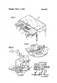
- FIG. 2 is a partial perspective view of the organ of FIG. 1;
- FIG. 3 is a partially perspective,"partially block diagram view of the organ of FIG. 1.
- FIG. 1 illustrates an organ 10 of a type which utilizes an optical disc record 12 to generate musical sounds.
- the organ has a playing portion 14 at the front of the organ housing 16, and a musician is normally seated at the front of the organ housing to play the organ.
- a group of piano-type keys of a keyboard 18 of the playing portion can be depressed by a musician to play a melody.
- Buttons of a chord" section 20 of the the playing portion can be depressed by a musician to play sounds that are useful for accompanying a melody. As shown in FIG.
- the optical disc record 12 includes a set of tone tracks 22 representing sustained tones such as those which might be produced by a violin or mandolin, and a set of accompanyment tracks 24 which define patterns of musical sounds that are suitable for accompanying a melody.
- Such patterns may include, for example, a succession of notes by one or more instruments in a waltz pattern for accompanying a waltz-type melody, with different record tracks being based on the key of C, the key of G, etc.
- some of the accompanyment patterns may be produced by percussion instruments. A musician generally sits in front of the organ housing, playing the keys of keyboard 18 with his right hand and depressing the buttons of the "chord section 20 with his left hand.
- a synchronizing window 26 is provided at the front of the organ housing 16, which flashes a light at the beginning of each musical measure. A musician therefore may depress one of the accompanyment buttons 20 as the light in window 26 blinks on, and the accompanyment pattern will be heard to begin at the beginning of a musical measure.
- the organ also includes a tremolo selector switch 28 which can be moved to an 0N position to create a tremolo effect, that is, arapid variation in the volume of sound.
- the optical disc organ is constructed to provide a synchronizing light at the window 26 and a tremolo effect,-with a minimum of parts in addition to those which are already required for the organ.
- the organ employs a light source 30 on the bottom side of the disc record 12, the light source generally including an elongated lamp and reflecting and collimating apparatus to direct beams of light through tracks of the disc record.
- Two groups of photocells 32 and 34 are positioned on a side of the disc record opposite the light source 30 to receive light that shines through the music tracks.
- the group of photocells 32 is positioned opposite those tracks which represent sustained musical tones while the other group of cells 34 is positioned opposite those tracks which represent accompanyment music patterns.
- the cells in the groups 32 and 34 generate electrical signals representing the music recorded on the record tracks. As shown in FIG.
- the output of the cells 32 is coupled through switches of the keyboard 18 to a first terminal 64 of the tremolo switch 28, the first terminal being located at an end of lead 36.
- the signals from the cells 34 are coupled through switches of the chord section 20 and through a variable resistor volume control 78 to the amplifier 40 and loudspeaker 42.
- the signals reaching the terminal 64 are carried through the switch 28 and eventually to the amplifier 40 and loudspeaker 42 for producing audible sounds representing the tones and accompanyment patterns recorded on the disc record.
- the disc record is rotatably mounted by a spindle 44 that projects through a hole at the center of the record, and is driven at a speed such as one revolution every four seconds by a pair of drive rollers 46. As the record rotates and a musician depresses keys of the keyboard and buttons of the chord section, music is produced.
- the accompanyment tracks 24 on the record have a duration of two musical measures along their 360 length, with one measure of all accompanyment tracks beginning along the imaginary radial line 47 and the other measure of each accompanyment track beginning along another imaginary radial line 48.
- the lines 47 and 48 are fixed with relation to the disc record.
- a new measure of an accompanyment pattern begins.
- the synchronizing track has a transparent region 52, 54 lying on each of the radial lines 47, 48 representing the beginning of a musical measure of the accompanyment patterns.
- the light source 30 is constructed to project some light through the synchronizing track 50.
- a light pipe 56 is mounted in the housing with one end 58 positioned adjacent to the synchronizing track at a location opposite the light source 30 and another end positioned at the window 26 in the organ housing.
- the light pipe can be formed by a plastic rod or a fiber optic bundle.
- the optical disc record 12 is constructed with a tremolo track 60 containing many transparent and opaque regions uniformly spaced thereabout.
- a tremolo photoresistor 62 is positioned adjacent to the tremolo track, on a side of the record opposite the light source 30 to receive light that passes through the tremolo track.
- the tremolo photoresistor 62 is of a type that changes resistance in accordance with the intensity of light incident thereon.
- the musical signals produced by the photocell 32 can be coupled through the tremolo photoresistor 62 by the tremolo selector switch 28. When the switch 28 is in the position shown in FIG.
- the signals representing musical sounds must pass through the tremolo photoresistor, and they therefore undergo a rapid variation in amplitude. Accordingly, the sound produced by the loudspeaker 42 rapidly varies to provide a tremolo effect.
- the transparent and opaque regions of the tremolo track 60 are of a number that provides a variation in resistance of the tremolo photoresistor of about five to seven variations per second. It may be noted that the transparent and opaque regions of the tremolo track do not have to be completely transparent or opaque, so long as there is a change in opacity. In some cases, the tremolo track is defined by a transparent region between opaque borders, the transparent region varying sinusoidally in width.
- the tremolo switch 28 has a first terminal 64 to which the outputs of the keyboard 18 are coupled, a second tenninal 66 that is coupled to the tremolo photoresistor 62 and a third terminal 68.
- the third terminal is connected to carry electrical signals to the amplifier 40 that leads to the loudspeaker, in a manner that bypasses the tremolo photoresistor.
- the musician can operate a lever on the housing to switch the tremolo switch from a position to produce a tremolo effect to another position to eliminate the effect.
- the organ is provided with a swell pedal 70.
- the swell pedal is provided in addition to a hand operated volume control 78, and the degree of foot pressure on the pedal determines the degree of volume increase over a minimum level previously established by the hand operated volume control.
- the pedal 70 operates a linkage 72 that opens and closes a light shutter 74.
- the shutter 74 controls the amount of light passing from the light source 30 to a swell photoresistor 76.
- the swell photoresistor 76 which has a resistance dependent upon the light incident thereon, is connected to the input of the amplifier 40 to control the amount of current flowing to the amplifier.
- volume control 78 is a variable resistor that is connected in parallel with the swell photoresistor 76, to allow for a hand setting of the minimum volume level.
- the invention provides an optical disc organ which has the feature of a synchronizing signal that indicates locations along measures of the accompanyment patterns, and the feature of a selectable tremolo effect.
- These features are provided with a minimum of additional complexity and cost to the organ, by utilizing an optical disc with synchronizing and tremolo tracks.
- These additional tracks can be included in the optical disc record at a minimal additional cost, inasmuch as they can be produced at the same time and in the same manner as the other tracks that represent musical sounds; that is, they can be produced during the exposing and developing of a photographic emulsion on the record.
- a plastic light pipe or other means is required to direct light that passes through the synchronizing track to a position where the light can be seen by a musician.
- a simple photoresistor is required that can be connected in series with musical signals that are to be carried to an amplifier and loudspeaker.
- Light for operating the synchronizing and tremolo apparatus can be obtained from the same light source that is used to project light through the musical tracks of the disc record. This light source can also be used to illuminate a swell photoresistor that allows a musician to rapidly change volume.
- An organ useful with an optical disc record which has a plurality of circular music tracks of variable opacity defining musical sounds to be played and a synchronizing track with opaque and transparent regions spaced therealong comprising:
- an organ housing having a playing portion for operation by a musician
- photodetector means responsive to light from said record for producing electrical signals representing said musical sounds
- the organ described in claim 1 including: an optical disc record having a plurality of concentric circular music tracks of variable opacity extending 360 thereabout, each of said music tracks defining a rhythm pattern of musical notes lasting for a whole number of musical measures along the 360 length of the track, and said disc also having a synchronizing track which has a transparent region preceded and followed by opaque regions, for each measure of said music tracks; and wherein said light means is constructed to' direct light at positions along said music and synchronizing tracks so that when light is being directed at said transparent region of said synchronizing track, light is also being directed at portions of said music tracks representing the beginning of a measure of said rhythmic pattern.
- portions of said music tracks representing the beginning of musical measures are arranged along an imaginary line radiating substantially from the center of said disc;
- said transparent region of said synchronizing track is located along said imaginary line
- said light means is elongated in a direction parallel t0 the direction assumed by said imaginary line when said imaginary line is adjacent to said light means.
- An organ and record assembly comprising:
- an optical disc record having a plurality of concentric circular music tracks of variable opacity and a circular tremolo track which varies in opacity
- first photodetector means responsive to light from said music tracks of said record for producing electrical signals representing said musical sounds
- said second photodetector means includes a resistor whose resistance varies in accordance with the intensity of light thereon;
- said means for producing audible sounds includes amplifying means, speaker means coupled to the output of said amplifying means, and means for coupling electrical signals from said first photodetector means through said resistor to said amplifying means.
- An organ useful with an optical disc record which has a plurality of circular music tracks of variable opacity defining musical sounds to be played and a synchronizing track with opaque and transparent regions spaced thereabout comprising:
- an organ housing having a keyboard region for operation by a musician
- a light source mounted within said organ housing on a first side of the position of an optical disc record therein, for directing light through said music tracks and synchronizing track of said record;
- speaker means for producing audible sounds
- switch means including manually operable portions at said keyboard region, for selectively coupling said photocells to said speaker means
- an elongated light pipe having a first end positioned on said second side of an optical disc record in said organ housing and adjacent to said synchronizing track thereof to receive light which has passed through said synchronizing track, and a second end positioned to be seen by a musician who is stationed at said keyboard region.
- said optical disc record includes a tremolo track having a plurality of substantially opaque regions separated by substantially transparent regions; and including a tremolo photodetector positioned'on said second side of said record adjacent to said tremolo track of a disc record in said organ; and
- tremolo selector means for coupling said switch means to said speaker means selectively in a path through said tremolo photodetector or in a path that by passes said tremolo photodetector.
- An organ useful with an optical disc record which has a plurality of circular music tracks of variable opacity defining musical sounds to be played and a circular tremolo track of variable opacity comprising:
- first photodetector means responsive to light from said music tracks of said record for producing electrical signals representing said musical sounds
- resistor with first and second terminals, said resistor having a resistance that varies in accordance with the intensity of light thereon and positioned to receive light passing through said tremolo track;
- speaker means coupled to the output of said amplifying means
- a switch having a first switch terminal coupled to said first photodetector means, a second switch terminal coupled to said second terminal of said resistor, a third switch terminal coupled to said amplifying means in a path that bypasses said resistor, and manually operable means for selectively connecting said first switch terminal to said second or third switch terminals.
Abstract
An organ of the type which utilizes an optical disc record with tracks that control the passage of light from a light source to photocells to create musical sounds, wherein the disc also has a synchronizing track to indicate the beginning of musical measures on certain music tracks and a tremolo track for creating a tremolo effect. A light-transmitting conduit has one end positioned to pick up light passing through the synchronizing track and an opposite end facing a musician seated at the organ keyboard, to provide a flash of light which can be seen by the musician at the beginning of each measure of certain musical tracks. A resistance photocell is positioned opposite the tremolo track and is connected between the photocells of the music track and the organ speaker, to provide a rapid variation in the volume of music.
Description
United States Patent Chang et al. 1 Mar. 7, 1972 [54] ELECTRONIC ORGAN WHEREIN 3,086,122 4/1963 Jones ..84/l.18 X MUSICAL SOUNDS AND A TREMOLO 3,197,543 7/1965 Wi1liams.... "WM/1.28 3,250,845 5 1966 Peterson.... ..84 1.25 D BY ELECTRO 3,325,581 6/1967 Young ..84/ 1.24 3,329,761 7/1967 Welsh.... .....84/l.l8 72 lnventors; i d S Chang, Rolling Hills Estates; 3,405,223 10/1968 Pavla ..84/ 1.18 Smiley cud", Van Nuys; Harvey La 3,461,217 8/1969 Omura et al. ..84/1.08 Branche, Palos Verdes Peninsula;
MW Mn w. 11' d1 ,1..-A' ,-1
dymon 08, nkeles d I of Cam Attorney-Seymour A. Scholmck [73] Assignee: Mattel Inc., Hawthorne, Calif. 22 Filed: Dec. 11,1970 [57] ABSTRACT An organ of the type which utilizes an optical disc record with [21] Appl 972l4 tracks that control the passage of light from a light source to photocells to create musical sounds, wherein the disc also has 52 [1.8. CI ..s4/1.1s, 84/1.25 a synchronizing track to indicate the beginning of musical 51 1m.c1 ..(;1011 1/02,G10h 3/06 measures on certain music tracks and a tremolo track for 58 Field of Search ..s4/1.1s, 1.28, 1.25, 1.24, creating a tremolo effect A light-transmitting conduit has one 34/1); 19, DIG 4, 470 477 R end positioned to pick up light passing through the synchronizing track and an opposite end facing a musician [561 References Cited seated at the organ keyboard, to provide a flash of light which can be seen by the musician at the beginning of each measure UNITED STATES PATENTS of certain musical tracks. A resistance photocell is positioned opposite the tremolo track and is connected between the 3,214,507 [0/1965 Williams ..84/l.l8 photoceus of the music track and the organ speaker to 1 vide a rapid variation in the volume of music. 3,045,522 7/ 1962 Markowitz et al. ..84/1.27 8 Claims, 3 Drawing Figures ELECTRONIC ORGAN WHEREIN MUSICAL SOUNDS AND A TREMOLO EFFECT ARE PROVIDED BY ELECTRO-OPTICAL APPARATUS BACKGROUND OF THE INVENTION 1. Field of the Invention This invention relates to organs, and more particularly to an organ of the type which utilizes an optical disc record through which light passes to photocells to create musical sounds.
2. Description of the Prior Art One type of electronic organ utilizes an optical disc record which has many concentric music tracks defining musical sounds to be played. Some of the tracks can define sustained tones, while other tracks define patterns of tones suitable for accompanying certain types of melodies. Each of the tracks that represents a pattern of notes extends for one or more whole musical measures in its 360 extension around the record. A musician may depress a chor button on the organ with his left hand to play an accompanyment pattern while playing an appropriate melody with his right hand. It is generally desirable to begin the accompanyment pattern at the beginning, or some other known point of a musical measure. A lamp which flashes on briefly at the beginning of each measure can provide an indication to a musician of when the beginning of a musical measure occurs. Various devices could be utilized to couple an optical disc record to a lamp in the organ to provide such an indication. However, it is desirable that such apparatus be as simple as possible to increase the reliability of the organ and keep its price as low as possible.
In many situations, a musical passage is enhanced by providing a rapid variation in it volume, at a rate such as 6 cycles per second, such a rapid variation generally being referred to as tremolo. Many devices are available to provide such a rapid variation, including rotating wheels and low frequency oscillator circuits. Although such devices are generally not very expensive, they add an appreciable cost to an organ. Apparatus which could be utilized with an optical disc organ to add a tremolo effect at a minimal increase in complexity and cost would aid in increasing the reliability and decreasing the cost of producing such an organ.
OBJECTS AND SUMMARY OF THE INVENTION An object of the present invention is to provide a simple apparatus useful in an optical disc organ to provide a blinking light that indicates the start of musical measures.
Another object is to provide simple apparatus useful in an optical disc organ to create a tremolo effect.
In accordance with one embodiment of the present invention, a simplified optical disc organ is provided which utilizes an optical disc to create a synchronizing light indicating the beginning of musical measures and to provide tremolo effects. The organ is designed to use a specially prepared optical disc' which has circular tracks. Some of the tracks contain 'pattems of musical notes of a length of one or more whole musical measures, and one of the tracks is a synchronizing track with a transparent region at the beginning of each musical measure. A light pipe is mounted in the organ with one end opposite the synchronizing track to pick up light shining therethrough and an opposite end positioned to be seen by a musician-seated at the organ keyboard. The musician can see the light blinking on at the beginning of each musical measure. This indicates when the musician can start to depress a button to sound an accompanyment pattern, so as to be sure the pattern is synchronized with the melody which the musician is playing on the keyboard.
The optical disc record is also constructed with a tremolo track which contains many alternating transparent and opaque regions. A resistance photocell is positioned adjacent to the tremolo track to receive light that shines through the track. The output of other photocells positioned opposite the musical tracks to generate electrical signals representing musiphotocell varies rapidly as light is alternately blocked and passed through the tremolo track, to rapidly vary the volume of sound.
The novel features of the invention are set forth with particularity in the appended claims. The invention will be best understood from the following description when read in conjunction with the accompanying drawings.
BRIEF DESCRIPTION OF THE DRAWINGS FIG. 1 is a perspective view of an organ constructed in accordance with one embodiment of the present invention;
FIG. 2 is a partial perspective view of the organ of FIG. 1; and
FIG. 3 is a partially perspective,"partially block diagram view of the organ of FIG. 1.
DESCRIPTION OF THE PREFERRED EMBODIMENTS FIG. 1 illustrates an organ 10 of a type which utilizes an optical disc record 12 to generate musical sounds. The organ has a playing portion 14 at the front of the organ housing 16, and a musician is normally seated at the front of the organ housing to play the organ. A group of piano-type keys of a keyboard 18 of the playing portion, can be depressed by a musician to play a melody. Buttons of a chord" section 20 of the the playing portion can be depressed by a musician to play sounds that are useful for accompanying a melody. As shown in FIG. 2, the optical disc record 12 includes a set of tone tracks 22 representing sustained tones such as those which might be produced by a violin or mandolin, and a set of accompanyment tracks 24 which define patterns of musical sounds that are suitable for accompanying a melody. Such patterns may include, for example, a succession of notes by one or more instruments in a waltz pattern for accompanying a waltz-type melody, with different record tracks being based on the key of C, the key of G, etc. Also, some of the accompanyment patterns may be produced by percussion instruments. A musician generally sits in front of the organ housing, playing the keys of keyboard 18 with his right hand and depressing the buttons of the "chord section 20 with his left hand.
When the musician wishes to start playing a song, he generally must know when to begin playing the melody so that it will be synchronized with any accompanyment pattern that he plays. Of course, he can first play one or more measures of the accompanyment pattern to determine when to come in with the melody, but he may not wish to always begin songs in this manner. In order to indicate when to begin, a synchronizing window 26 is provided at the front of the organ housing 16, which flashes a light at the beginning of each musical measure. A musician therefore may depress one of the accompanyment buttons 20 as the light in window 26 blinks on, and the accompanyment pattern will be heard to begin at the beginning of a musical measure. It may be noted that the accompanyment patterns may include introductory measures which begin a pattern in the middle of a measure, but it is still desirable to know when the pattern will begin. The organ also includes a tremolo selector switch 28 which can be moved to an 0N position to create a tremolo effect, that is, arapid variation in the volume of sound. The optical disc organ is constructed to provide a synchronizing light at the window 26 and a tremolo effect,-with a minimum of parts in addition to those which are already required for the organ.
In'order to create musical sounds, the organ employs a light source 30 on the bottom side of the disc record 12, the light source generally including an elongated lamp and reflecting and collimating apparatus to direct beams of light through tracks of the disc record. Two groups of photocells 32 and 34 are positioned on a side of the disc record opposite the light source 30 to receive light that shines through the music tracks. The group of photocells 32 is positioned opposite those tracks which represent sustained musical tones while the other group of cells 34 is positioned opposite those tracks which represent accompanyment music patterns. The cells in the groups 32 and 34 generate electrical signals representing the music recorded on the record tracks. As shown in FIG. 3, the output of the cells 32 is coupled through switches of the keyboard 18 to a first terminal 64 of the tremolo switch 28, the first terminal being located at an end of lead 36. The signals from the cells 34 are coupled through switches of the chord section 20 and through a variable resistor volume control 78 to the amplifier 40 and loudspeaker 42. The signals reaching the terminal 64, are carried through the switch 28 and eventually to the amplifier 40 and loudspeaker 42 for producing audible sounds representing the tones and accompanyment patterns recorded on the disc record. The disc record is rotatably mounted by a spindle 44 that projects through a hole at the center of the record, and is driven at a speed such as one revolution every four seconds by a pair of drive rollers 46. As the record rotates and a musician depresses keys of the keyboard and buttons of the chord section, music is produced.
Referring to FIG. 2, the accompanyment tracks 24 on the record have a duration of two musical measures along their 360 length, with one measure of all accompanyment tracks beginning along the imaginary radial line 47 and the other measure of each accompanyment track beginning along another imaginary radial line 48. The lines 47 and 48 are fixed with relation to the disc record. At the instant when each line 47, 48 comes under the photocells 34, a new measure of an accompanyment pattern begins. As mentioned above, a light blinks on at the window 26 at the instant when a new measure begins. in order to create such a blinking light, the optical disc record 12 is formed with a synchronizing track 50 concentric with the record. The synchronizing track has a transparent region 52, 54 lying on each of the radial lines 47, 48 representing the beginning of a musical measure of the accompanyment patterns. The light source 30 is constructed to project some light through the synchronizing track 50. A light pipe 56 is mounted in the housing with one end 58 positioned adjacent to the synchronizing track at a location opposite the light source 30 and another end positioned at the window 26 in the organ housing. The light pipe can be formed by a plastic rod or a fiber optic bundle. Each time a transparent region 52, 54 of the synchronizing track comes between the light source and light pipe end 52, the musician can see a light at the window 26. This informs the musician that a musical measure of the accompanyment pattern is beginning.
In order to create a tremolo effect, the optical disc record 12 is constructed with a tremolo track 60 containing many transparent and opaque regions uniformly spaced thereabout. A tremolo photoresistor 62 is positioned adjacent to the tremolo track, on a side of the record opposite the light source 30 to receive light that passes through the tremolo track. The tremolo photoresistor 62 is of a type that changes resistance in accordance with the intensity of light incident thereon. Thus, as the disc record rotates, the resistance of the photocell 62 rapidly varies. The musical signals produced by the photocell 32 can be coupled through the tremolo photoresistor 62 by the tremolo selector switch 28. When the switch 28 is in the position shown in FIG. 3, the signals representing musical sounds must pass through the tremolo photoresistor, and they therefore undergo a rapid variation in amplitude. Accordingly, the sound produced by the loudspeaker 42 rapidly varies to provide a tremolo effect. Typically, the transparent and opaque regions of the tremolo track 60 are of a number that provides a variation in resistance of the tremolo photoresistor of about five to seven variations per second. It may be noted that the transparent and opaque regions of the tremolo track do not have to be completely transparent or opaque, so long as there is a change in opacity. In some cases, the tremolo track is defined by a transparent region between opaque borders, the transparent region varying sinusoidally in width.
The tremolo switch 28 has a first terminal 64 to which the outputs of the keyboard 18 are coupled, a second tenninal 66 that is coupled to the tremolo photoresistor 62 and a third terminal 68. The third terminal is connected to carry electrical signals to the amplifier 40 that leads to the loudspeaker, in a manner that bypasses the tremolo photoresistor. The musician can operate a lever on the housing to switch the tremolo switch from a position to produce a tremolo effect to another position to eliminate the effect.
In order to allow a musician to control volume while playing a composition, the organ is provided with a swell pedal 70. The swell pedal is provided in addition to a hand operated volume control 78, and the degree of foot pressure on the pedal determines the degree of volume increase over a minimum level previously established by the hand operated volume control. As shown in FIG. 3, the pedal 70 operates a linkage 72 that opens and closes a light shutter 74. The shutter 74 controls the amount of light passing from the light source 30 to a swell photoresistor 76. The swell photoresistor 76, which has a resistance dependent upon the light incident thereon, is connected to the input of the amplifier 40 to control the amount of current flowing to the amplifier. The greater the depression of the swell pedal 70, the more light is incident on the photoresistor 76 and the lower its resistance. The lower resistance results in a greater signal input to the amplifier 40 and therefore a greater volume. It may be noted that the volume control 78 is a variable resistor that is connected in parallel with the swell photoresistor 76, to allow for a hand setting of the minimum volume level.
Thus, the invention provides an optical disc organ which has the feature of a synchronizing signal that indicates locations along measures of the accompanyment patterns, and the feature of a selectable tremolo effect. These features are provided with a minimum of additional complexity and cost to the organ, by utilizing an optical disc with synchronizing and tremolo tracks. These additional tracks can be included in the optical disc record at a minimal additional cost, inasmuch as they can be produced at the same time and in the same manner as the other tracks that represent musical sounds; that is, they can be produced during the exposing and developing of a photographic emulsion on the record. To provide synchronizing signals, a plastic light pipe or other means is required to direct light that passes through the synchronizing track to a position where the light can be seen by a musician. To provide the tremolo effect, a simple photoresistor is required that can be connected in series with musical signals that are to be carried to an amplifier and loudspeaker. Light for operating the synchronizing and tremolo apparatus can be obtained from the same light source that is used to project light through the musical tracks of the disc record. This light source can also be used to illuminate a swell photoresistor that allows a musician to rapidly change volume.
Although particular embodiments of the invention have been described and illustrated herein, it is recognized that modifications and variations may readily occur to those skilled in the art and, consequently, it is intended that the claims be interpreted to cover such modifications and equivalents.
What is claimed is:
1. An organ useful with an optical disc record which has a plurality of circular music tracks of variable opacity defining musical sounds to be played and a synchronizing track with opaque and transparent regions spaced therealong comprising:
an organ housing having a playing portion for operation by a musician;
disc driving means mounted within said housing for rotating said optical disc record;
light means mounted within said organ housing for directing light at said music tracks and synchronizing track of said record;
photodetector means responsive to light from said record for producing electrical signals representing said musical sounds;
means responsive to operation of said playing portion by a musician and to said photodetector means for producing audible sounds; and
light carrying means having an input positioned to receive light from said light means which has passed through said synchronizing track and an output positioned to be seen by a musician who is stationed at said playing portion. 2. The organ described in claim 1 including: an optical disc record having a plurality of concentric circular music tracks of variable opacity extending 360 thereabout, each of said music tracks defining a rhythm pattern of musical notes lasting for a whole number of musical measures along the 360 length of the track, and said disc also having a synchronizing track which has a transparent region preceded and followed by opaque regions, for each measure of said music tracks; and wherein said light means is constructed to' direct light at positions along said music and synchronizing tracks so that when light is being directed at said transparent region of said synchronizing track, light is also being directed at portions of said music tracks representing the beginning of a measure of said rhythmic pattern.
3. The organ described in claim 2 wherein:
portions of said music tracks representing the beginning of musical measures are arranged along an imaginary line radiating substantially from the center of said disc;
said transparent region of said synchronizing track is located along said imaginary line; and
said light means is elongated in a direction parallel t0 the direction assumed by said imaginary line when said imaginary line is adjacent to said light means.
4. An organ and record assembly comprising:
an optical disc record having a plurality of concentric circular music tracks of variable opacity and a circular tremolo track which varies in opacity;
an organ housing;
disc driving means mounted within said housing for rotating said optical disc record;
light means mounted within said organ housing for directing light at said music tracks and tremolo track of said record;
first photodetector means responsive to light from said music tracks of said record for producing electrical signals representing said musical sounds;
second photodetector means positioned to receive light passing through said tremolo track; and
means responsive to electrical signals from said first photodetector means and to said second photodetector means, for producing audible sounds representing said electrical signals of a volume dependent upon the amount of light received by said second photodetector means.
5. The organ described in claim 4 wherein:
said second photodetector means includes a resistor whose resistance varies in accordance with the intensity of light thereon; and
said means for producing audible sounds includes amplifying means, speaker means coupled to the output of said amplifying means, and means for coupling electrical signals from said first photodetector means through said resistor to said amplifying means.
6. An organ useful with an optical disc record which has a plurality of circular music tracks of variable opacity defining musical sounds to be played and a synchronizing track with opaque and transparent regions spaced thereabout comprising:
an organ housing having a keyboard region for operation by a musician;
disc driving means mounted within said housing for rotating said optical disc record;
a light source mounted within said organ housing on a first side of the position of an optical disc record therein, for directing light through said music tracks and synchronizing track of said record;
a plurality of photocells positioned on a second side of an optical disc record in said organ housing to receive light which has passed through said music tracks of a record;
speaker means for producing audible sounds; a plurality of switch means including manually operable portions at said keyboard region, for selectively coupling said photocells to said speaker means; and
an elongated light pipe having a first end positioned on said second side of an optical disc record in said organ housing and adjacent to said synchronizing track thereof to receive light which has passed through said synchronizing track, and a second end positioned to be seen by a musician who is stationed at said keyboard region.
7. The organ described in claim 6 wherein:
said optical disc record includes a tremolo track having a plurality of substantially opaque regions separated by substantially transparent regions; and including a tremolo photodetector positioned'on said second side of said record adjacent to said tremolo track of a disc record in said organ; and
tremolo selector means for coupling said switch means to said speaker means selectively in a path through said tremolo photodetector or in a path that by passes said tremolo photodetector.
8. An organ useful with an optical disc record which has a plurality of circular music tracks of variable opacity defining musical sounds to be played and a circular tremolo track of variable opacity comprising:
an organ housing;
disc driving means mounted within said housing for rotating said optical disc record;
light means mounted within said organ housing for directing light at said music tracks and tremolo track of said record;
first photodetector means responsive to light from said music tracks of said record for producing electrical signals representing said musical sounds;
a resistor with first and second terminals, said resistor having a resistance that varies in accordance with the intensity of light thereon and positioned to receive light passing through said tremolo track;
amplifying means;
speaker means coupled to the output of said amplifying means;
means for coupling said first terminal of said resistor to said amplifying means; and
a switch having a first switch terminal coupled to said first photodetector means, a second switch terminal coupled to said second terminal of said resistor, a third switch terminal coupled to said amplifying means in a path that bypasses said resistor, and manually operable means for selectively connecting said first switch terminal to said second or third switch terminals.
w-qg UNITED 5mm PATENT @FFTC'E QERTTETQATE 0F GQRREQTTUN 3,647,927 Dated March 7, 1972 Patent No.
inimntofls) Richard 5. Chang e a1 It is certified that error appears in the above-identified patent ans that said Letters Patent are hereby corrected as shown below:
The name of the inventor Raymond 'Toy appears in the inventor headingas M. Raymond Toy. This should be corrected to .read Raymond M. Toy.
Signed and sealed this Zhth day of October 1972.
(SEAL) Attest:
EDWARD M.FLETCI-IER,JR ROBERT GOTTS CHALK Attestlng Offlcer Commissioner of Patents UNETEU STATES PATENT FFICE QERTHFKCATE @TF CUJEKHECTKQN pa n 5, 3,647,927 Dated March 7, 1972 inventofls) Richard S Chang et a1 It is certified that error appears in the above-identified patent and that said Letters Patent are. hereby corrected as shown below:
Toy appears in the inventor headingas M. Raymond Toy. be corrected to .read Raymond M. Toy
Signed and sealed this Zhth day of October 1972,
(SEAL) Attest:
EDWARD M FLETCHERJR ROBERT GOTI' y SCHALK Attestlng Officer Commissioner of" Patents
Claims (8)
1. An organ useful with an optical disc record which has a plurality of circular music tracks of variable opacity defining musical sounds to be played and a synchronizing track with opaque and transparent regions spaced therealong comprising: an organ housing having a playing portion for operation by a musician; disc driving means mounted within said housing for rotating said optical disc record; light means mounted within said organ housing for directing light at said music tracks and synchronizing track of said record; photodetector means responsive to light from said record for producing electrical signals representing said musical sounds; means responsive to operation of said playing portion by a musician and to said photodetector means for producing audible sounds; and light carrying means having an input positioned to receive light from said light means which has passed through said synchronizing track and an output positioned to be seen by a musician who is stationed at said playing portion.
2. The organ described in claim 1 including: an optical disc record having a plurality of concentric circular music tracks of variable opacity extending 360* thereabout, each of said music tracks defining a rhythm pattern of musical notes lasting for a whole number of musical measures along the 360* length of the track, and said disc also having a synchronizing track which has a transparent region preceded and followed by opaque regions, for each measure of said music tracks; and wherein said light means is constructed to direct light at positions along said music and synchronizing tracks so that when light is being directed at said transparent region of said synchronizing track, light is also being directed at portions of said music tracks representing the beginning of a measure of said rhythmic pattern.
3. The organ described in claim 2 wherein: portions of said music tracks representing the beginning of musical measures are arranged along an imaginary line radiating substantially from the center of said disc; said transparent region of said synchronizing track is located along said imaginary line; and said light means is elongated in a direction parallel tO the direction aSsumed by said imaginary line when said imaginary line is adjacent to said light means.
4. An organ and record assembly comprising: an optical disc record having a plurality of concentric circular music tracks of variable opacity and a circular tremolo track which varies in opacity; an organ housing; disc driving means mounted within said housing for rotating said optical disc record; light means mounted within said organ housing for directing light at said music tracks and tremolo track of said record; first photodetector means responsive to light from said music tracks of said record for producing electrical signals representing said musical sounds; second photodetector means positioned to receive light passing through said tremolo track; and means responsive to electrical signals from said first photodetector means and to said second photodetector means, for producing audible sounds representing said electrical signals of a volume dependent upon the amount of light received by said second photodetector means.
5. The organ described in claim 4 wherein: said second photodetector means includes a resistor whose resistance varies in accordance with the intensity of light thereon; and said means for producing audible sounds includes amplifying means, speaker means coupled to the output of said amplifying means, and means for coupling electrical signals from said first photodetector means through said resistor to said amplifying means.
6. An organ useful with an optical disc record which has a plurality of circular music tracks of variable opacity defining musical sounds to be played and a synchronizing track with opaque and transparent regions spaced thereabout comprising: an organ housing having a keyboard region for operation by a musician; disc driving means mounted within said housing for rotating said optical disc record; a light source mounted within said organ housing on a first side of the position of an optical disc record therein, for directing light through said music tracks and synchronizing track of said record; a plurality of photocells positioned on a second side of an optical disc record in said organ housing to receive light which has passed through said music tracks of a record; speaker means for producing audible sounds; a plurality of switch means including manually operable portions at said keyboard region, for selectively coupling said photocells to said speaker means; and an elongated light pipe having a first end positioned on said second side of an optical disc record in said organ housing and adjacent to said synchronizing track thereof to receive light which has passed through said synchronizing track, and a second end positioned to be seen by a musician who is stationed at said keyboard region.
7. The organ described in claim 6 wherein: said optical disc record includes a tremolo track having a plurality of substantially opaque regions separated by substantially transparent regions; and including a tremolo photodetector positioned on said second side of said record adjacent to said tremolo track of a disc record in said organ; and tremolo selector means for coupling said switch means to said speaker means selectively in a path through said tremolo photodetector or in a path that by passes said tremolo photodetector.
8. An organ useful with an optical disc record which has a plurality of circular music tracks of variable opacity defining musical sounds to be played and a circular tremolo track of variable opacity comprising: an organ housing; disc driving means mounted within said housing for rotating said optical disc record; light means mounted within said organ housing for directing light at said music tracks and tremolo track of said record; first photodetector means responsive to light from said music tracks of said record for producing electrical signals representing said musical sounds; a resistor with fIrst and second terminals, said resistor having a resistance that varies in accordance with the intensity of light thereon and positioned to receive light passing through said tremolo track; amplifying means; speaker means coupled to the output of said amplifying means; means for coupling said first terminal of said resistor to said amplifying means; and a switch having a first switch terminal coupled to said first photodetector means, a second switch terminal coupled to said second terminal of said resistor, a third switch terminal coupled to said amplifying means in a path that bypasses said resistor, and manually operable means for selectively connecting said first switch terminal to said second or third switch terminals.
Applications Claiming Priority (1)
| Application Number | Priority Date | Filing Date | Title |
|---|---|---|---|
| US9721470A | 1970-12-11 | 1970-12-11 |
Publications (1)
| Publication Number | Publication Date |
|---|---|
| US3647927A true US3647927A (en) | 1972-03-07 |
Family
ID=22262122
Family Applications (1)
| Application Number | Title | Priority Date | Filing Date |
|---|---|---|---|
| US97214A Expired - Lifetime US3647927A (en) | 1970-12-11 | 1970-12-11 | Electronic organ wherein musical sounds and a tremolo effect are provided by electro-optical apparatus |
Country Status (6)
| Country | Link |
|---|---|
| US (1) | US3647927A (en) |
| CA (1) | CA934875A (en) |
| DE (2) | DE2161454A1 (en) |
| FR (1) | FR2117633A5 (en) |
| GB (1) | GB1360666A (en) |
| IT (1) | IT943209B (en) |
Cited By (3)
| Publication number | Priority date | Publication date | Assignee | Title |
|---|---|---|---|---|
| US3749808A (en) * | 1972-03-24 | 1973-07-31 | Mattel Inc | Low distortion optical organ |
| US4344346A (en) * | 1980-09-29 | 1982-08-17 | Marvin Glass & Associates | Musical light toy |
| US5451178A (en) * | 1992-03-26 | 1995-09-19 | Sony Corporation | Auditory playing device |
Citations (11)
| Publication number | Priority date | Publication date | Assignee | Title |
|---|---|---|---|---|
| US3045522A (en) * | 1960-03-17 | 1962-07-24 | Allen Organ Co | Light responsive variable resistance control devices for electronic musical instruments |
| US3086122A (en) * | 1959-08-17 | 1963-04-16 | Baldwin Piano Co | Photoelectric chorus effect generator |
| US3197543A (en) * | 1958-08-05 | 1965-07-27 | Dimension Inc | Photoelectric organ |
| US3214507A (en) * | 1962-03-21 | 1965-10-26 | Scope Inc | Photoelectric organ |
| US3249678A (en) * | 1962-03-05 | 1966-05-03 | Baldwin Co D H | Photoelectric organ and appurtenances |
| US3250845A (en) * | 1963-07-01 | 1966-05-10 | Richard H Peterson | Tremulant effect for electronic musical instruments |
| US3325581A (en) * | 1964-07-20 | 1967-06-13 | Hammond Organ Co | Organ chorus and celeste system utilizing randomly varying phase shift means |
| US3329761A (en) * | 1964-09-01 | 1967-07-04 | W W Kimball Company | Two channel tremolo |
| US3405223A (en) * | 1965-10-08 | 1968-10-08 | Pavia Farny Associates | Electronic organ |
| US3405222A (en) * | 1964-07-27 | 1968-10-08 | Joachim L. Heinzl | Multi-tone photoelectric musical instrument |
| US3461217A (en) * | 1966-06-27 | 1969-08-12 | Matsushita Electric Ind Co Ltd | Piano keyboard type electronic musical instrument having a bass pedal and single continuous keyboard |
-
1970
- 1970-12-11 US US97214A patent/US3647927A/en not_active Expired - Lifetime
-
1971
- 1971-11-26 GB GB5501171A patent/GB1360666A/en not_active Expired
- 1971-11-29 CA CA128856A patent/CA934875A/en not_active Expired
- 1971-12-09 IT IT71026/71A patent/IT943209B/en active
- 1971-12-10 FR FR7144415A patent/FR2117633A5/fr not_active Expired
- 1971-12-10 DE DE19712161454 patent/DE2161454A1/en active Pending
- 1971-12-10 DE DE19717146666U patent/DE7146666U/en not_active Expired
Patent Citations (11)
| Publication number | Priority date | Publication date | Assignee | Title |
|---|---|---|---|---|
| US3197543A (en) * | 1958-08-05 | 1965-07-27 | Dimension Inc | Photoelectric organ |
| US3086122A (en) * | 1959-08-17 | 1963-04-16 | Baldwin Piano Co | Photoelectric chorus effect generator |
| US3045522A (en) * | 1960-03-17 | 1962-07-24 | Allen Organ Co | Light responsive variable resistance control devices for electronic musical instruments |
| US3249678A (en) * | 1962-03-05 | 1966-05-03 | Baldwin Co D H | Photoelectric organ and appurtenances |
| US3214507A (en) * | 1962-03-21 | 1965-10-26 | Scope Inc | Photoelectric organ |
| US3250845A (en) * | 1963-07-01 | 1966-05-10 | Richard H Peterson | Tremulant effect for electronic musical instruments |
| US3325581A (en) * | 1964-07-20 | 1967-06-13 | Hammond Organ Co | Organ chorus and celeste system utilizing randomly varying phase shift means |
| US3405222A (en) * | 1964-07-27 | 1968-10-08 | Joachim L. Heinzl | Multi-tone photoelectric musical instrument |
| US3329761A (en) * | 1964-09-01 | 1967-07-04 | W W Kimball Company | Two channel tremolo |
| US3405223A (en) * | 1965-10-08 | 1968-10-08 | Pavia Farny Associates | Electronic organ |
| US3461217A (en) * | 1966-06-27 | 1969-08-12 | Matsushita Electric Ind Co Ltd | Piano keyboard type electronic musical instrument having a bass pedal and single continuous keyboard |
Cited By (3)
| Publication number | Priority date | Publication date | Assignee | Title |
|---|---|---|---|---|
| US3749808A (en) * | 1972-03-24 | 1973-07-31 | Mattel Inc | Low distortion optical organ |
| US4344346A (en) * | 1980-09-29 | 1982-08-17 | Marvin Glass & Associates | Musical light toy |
| US5451178A (en) * | 1992-03-26 | 1995-09-19 | Sony Corporation | Auditory playing device |
Also Published As
| Publication number | Publication date |
|---|---|
| DE7146666U (en) | 1972-05-31 |
| GB1360666A (en) | 1974-07-17 |
| DE2161454A1 (en) | 1972-06-22 |
| IT943209B (en) | 1973-04-02 |
| CA934875A (en) | 1973-10-02 |
| FR2117633A5 (en) | 1972-07-21 |
Similar Documents
| Publication | Publication Date | Title |
|---|---|---|
| Russ | Sound synthesis and sampling | |
| Mathews | The radio baton and conductor program, or: Pitch, the most important and least expressive part of music | |
| US3837256A (en) | Sight and sound musical instrument instruction | |
| US5668333A (en) | Musical rainbow toy | |
| MXPA01003089A (en) | Automatic music generating method and device. | |
| US3708602A (en) | An electronic organ with automatic chord and bass systems | |
| US5396827A (en) | Tuner with variable tuning window | |
| US4010667A (en) | Rhythm unit with programmed envelope waveform, amplitude, and the like | |
| US3647927A (en) | Electronic organ wherein musical sounds and a tremolo effect are provided by electro-optical apparatus | |
| US4422361A (en) | Electronic musical instrument | |
| US3885490A (en) | Single track sight and sound musical instrument instruction device | |
| EP0070293A1 (en) | Signal emitting device with adjustable beat frequency. | |
| US5286912A (en) | Electronic musical instrument with playback of background tones and generation of key-on phrase tones | |
| US3325581A (en) | Organ chorus and celeste system utilizing randomly varying phase shift means | |
| JPS6124998Y2 (en) | ||
| US3878751A (en) | Endless record audio signal generator and means for playing record | |
| US2469850A (en) | Electric musical instrument | |
| US4182214A (en) | Electronic musical instrument | |
| Dranch | A performer's approach to new demands in selected contemporary clarinet compositions | |
| JPS62150393A (en) | Electronic musical apparatus | |
| Bishop et al. | Music Circuits | |
| JPS6235116Y2 (en) | ||
| Beecher | Rhodes Chroma (EMM Oct 1982) | |
| Hurtig | Synthesizer basics | |
| JPH0610397Y2 (en) | Input device for electronic musical instruments |