US3741021A - Starter motors - Google Patents
Starter motors Download PDFInfo
- Publication number
- US3741021A US3741021A US00234613A US3741021DA US3741021A US 3741021 A US3741021 A US 3741021A US 00234613 A US00234613 A US 00234613A US 3741021D A US3741021D A US 3741021DA US 3741021 A US3741021 A US 3741021A
- Authority
- US
- United States
- Prior art keywords
- pinion assembly
- pinion
- starter motor
- assembly
- shaft
- Prior art date
- Legal status (The legal status is an assumption and is not a legal conclusion. Google has not performed a legal analysis and makes no representation as to the accuracy of the status listed.)
- Expired - Lifetime
Links
Images

Classifications
-
- F—MECHANICAL ENGINEERING; LIGHTING; HEATING; WEAPONS; BLASTING
- F02—COMBUSTION ENGINES; HOT-GAS OR COMBUSTION-PRODUCT ENGINE PLANTS
- F02N—STARTING OF COMBUSTION ENGINES; STARTING AIDS FOR SUCH ENGINES, NOT OTHERWISE PROVIDED FOR
- F02N15/00—Other power-operated starting apparatus; Component parts, details, or accessories, not provided for in, or of interest apart from groups F02N5/00 - F02N13/00
- F02N15/02—Gearing between starting-engines and started engines; Engagement or disengagement thereof
- F02N15/04—Gearing between starting-engines and started engines; Engagement or disengagement thereof the gearing including disengaging toothed gears
- F02N15/06—Gearing between starting-engines and started engines; Engagement or disengagement thereof the gearing including disengaging toothed gears the toothed gears being moved by axial displacement
-
- Y—GENERAL TAGGING OF NEW TECHNOLOGICAL DEVELOPMENTS; GENERAL TAGGING OF CROSS-SECTIONAL TECHNOLOGIES SPANNING OVER SEVERAL SECTIONS OF THE IPC; TECHNICAL SUBJECTS COVERED BY FORMER USPC CROSS-REFERENCE ART COLLECTIONS [XRACs] AND DIGESTS
- Y10—TECHNICAL SUBJECTS COVERED BY FORMER USPC
- Y10T—TECHNICAL SUBJECTS COVERED BY FORMER US CLASSIFICATION
- Y10T74/00—Machine element or mechanism
- Y10T74/13—Machine starters
- Y10T74/131—Automatic
Abstract
A starter motor for an internal combustion engine including a casing having journalled for rotation therein a rotor shaft. The rotor shaft carries an armature assembly and a pinion assembly is mounted on the rotor shaft by way of a helical screw thread for limited rotational and axial movement relative to the shaft. The pinion assembly can move relative to the shaft between an operative position and a retracted position, and frictionally engaged with the pinion assembly is a member which is engageable by a detent device. The detent device when engaged with the member, resists rotation of the member which in turn resists rotation of the pinion assembly. Thus when the rotor shaft rotates and the detent is operative then the pinion assembly is driven towards its operative position by the action of the helical screw thread. In the operative position of the pinion assembly the detent member engages behind the pinion assembly so as to resist movement of the pinion assembly towards its retracted position. The detent device is returned to a position clear of the pinion assembly when the starter motor is deenergized.
Description
United States Patent 91 Parsons STARTER MOTORS [75] Inventor: Nicholas Tyers Parsons, Exmouth,
England [73] Assignee: Joseph Lucas (Industries) Limited,
Birmingham, England [22] Filed: Mar. 14, 1972 [21] Appl. No.: 234,613
[30] Foreign Application Priority Data Apr. 3, 1971 Great Britain 8,628/71 [52] US. Cl 74/7 R [51] Int. Cl. F02n 11/00 [58] Field of Search 74/7 R, 6, 7 B
[56] 9 References Cited UNITED STATES PATENTS 3,465,353 9/1969 Buxton et a1. 74/7 3,496,759 2/1970 Buxton 74/7 Primary Examiner-Milton Kaufman Attorney-John C. Holman et al.
[5 7] ABSTRACT A starter motor for an internal combustion engine including a casing having journalled for rotation therein a rotor shaft. The rotor shaft carries an armature assembly and a pinion assembly is mounted on the rotor shaft by way of a helical screw thread for limited rotational and axial movement relative to the shaft. The pinion assembly can move relative to the shaft between an operative position and a retracted position, and frictionally engaged with the pinion assembly is a member which is engageable by a detent device. The detent device when engaged with the member, resists rotation of the member which in turn resists rotation of the pinion assembly. Thus when the rotor shaft rotates and the detent is operative then the pinion assembly is driven towards its operative position by the action of the helical screw thread. In the operative position of the pinion assembly the detent member engages behind the pinion assembly so as to resist movement of the pinion assembly towards its retracted position. The detent device is returned to a position clear of the pinion assembly when the starter motor is de-energized.
5 Claims, 3 Drawing Figures PAIENIEDwn'zs I973 SHEEI 1 0F 2 FIGE.
PAIENIEDJUN26 191a 3 741021 SHEET 2 [IF 2 FIG?) STARTER MOTORS This invention relates to starter motors for internal combustion engines.
A starter motor according to the invention, includes, a casing, a rotor shaft journalled in the casing for rotation relative to the casing and carrying an armature assembly, a pinion assembly mounted on the rotor shaft for limited rotational movement relative thereto, and capable of axial movement relative to the shaft between a retracted position and an operative position wherein in use a pinion of the pinion assembly drivingly engages a ring gear of an engine to be started, the shaft and the pinion assembly being inter-connected by way of a helical screw thread, amember frictionally engaged with the pinion assembly for rotation therewith, and a detent device engageable with said member so as to resist rotation of the member and thereby resist rota tion of the pinion assembly so that when the rotor shaft is rotated the pinion assembly is driven towards its operative position by the action of said helical screw thread, said detent devicein the operative position of the pinion assembly, engaging behind the pinion assembly so as to resist movement of the pinion assembly towards its retracted position, the detent device being returned to a position clear of the pinion assembly when the starter motor is de-energized.
Preferably, the detent device is electromechanically operated.
Conveniently, said member includes a toothed disc frictionally engaged with the pinion assembly, and said detent device is a pivoted lever movable to a position wherein it engages said toothed disc in a manner to resist rotation thereof.
One example of the invention is illustrated in the accompanying drawings wherein:
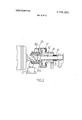
FIG. 1 is a part sectional view of a starter motor showing the pinion in its retracted position,
FIG. 2 is an end view in the direction of Arrow A in FIG. 1, and
FIG. 3 is a view similar to FIG. 1, but showing the pinion assembly in its operative position.
Referring to the drawings, the starter motor includes a casing 11 housing the mechanism of the starter motor. Journalled for rotation within the casing 11 is a rotor shaft 12, carrying the armature assembly 13 of the starter motor. The casing defines a pair of bearings for the rotor shaft 12, one of which is shown at 14. Between the bearing 14 and the armature assembly 13 the shaft 12 supports a pinion assembly generally indicated at 15. The pinion assembly 15 includes a sleeve 16 defining at its end adjacent the bearing 14 the outer part of acne way roller clutch 17, the pinion assembly 15 further includes a pinion 18 having integral therewith, at its end remote from the bearing 14, the inner part of the roller clutch 17. The pinion 18 contains a bearing shell through which extends a plain portion of the shaft 12, of reduced diameter. Adjacent the armature assembly 13 the shaft 12 is formed with a helical screwthread, which mates with a corresponding internal thread within the sleeve 16. A shoulder on the shaft 12 adjacent the armature assembly 13 defines a stop limiting movement of the pinion assembly along the shaft 12 towards the armature assembly, and a cup shaped abutment member 19 secured to the shaft 12 adjacent the bearing 14 defines a second abutment member limiting movement of the pinion assembly 15 along the shaft 12 in a direction towards the bearing 14. A light spring 21 acts between the member 19 and the pinion 18 to urge the pinion assembly 17 towards the armature assembly 13.
It will be appreciated, that the pinion assembly 15, ignoring for the moment the roller clutch 17 can be rotated bodily relative to the shaft 12 as permitted by the helical screw-threaded connection between the sleeve 16 and the shaft 12, and during such rotational movement will move axially relative to the shaft 12. The pinion has a retracted position as shown in FIG. 1, and has an operative position as shown in FIG. 3, in which in use the pinion 18 mates with the ring gear of an engine to be started. In the retracted position, the pinion 18 is clear of the ring gear of the engine.
Mounted for rotation on the sleeve 16 is a toothed disc 22 which has a cylindrical land 29 on one face thereof and which is urged by a heavy spring 23 into facial contact with a peripheral flange 24 of the sleeve 16. Pivotally mounted on the casing 11, at 25, (FIG. 2) is a part circular detent lever 26. The lever 26 is pivotally connected adjacent its mid-point to the casing at 25, and the limbs 26a, 26b of the lever 26 extend on opposite sides of the shaft 12. The limb 26b of the lever 26 extends adjacent a pair of electro-magnets 27 which are operated simultaneously, and so constitute a single electro-magnet. The lever 26 is urged to pivot relative to the casing by a spring 28 to a position wherein the limb 26b is'clear of the magnet 27, and the limb 26a is clear of the toothed disc 22.
The operation of the starter motor is as follows:
Energization of the starter motor to cause the shaft 12 to rotate simultaneously causes energization of the electromagnet 27. The magnet 27 when energizedattracts the limb 26b of the lever 26 and pivots the lever 26 against the action of the spring 28 to engage the free end of the limb 26a with the periphery of the toothed disc 22. As the shaft 12 starts to rotate, in a clockwise direction (as considered in FIG. 2) one of the peripheral teeth of the disc 22 is moved into engagement with the free end of the limb 26a whereupon further-rotation of the disc 22 is resisted by the lever 26. As previously stated, the spring 23 is quite strong, and so the frictional engagement of the disc 22 with the sleeve 16 is also quite strong. Thus rotation of the pinion assembly 17 relative to the casing 11 is resisted, and the shaft 12 rotates relative to the pinion assembly 17. By virtue of the helical screw-thread connection between the sleeve 16 and the shaft 12 rotation of the shaft 12 relative to the pinion assembly drives the pinion assembly axially towards its operative position against the action of the spring 21. Assuming that the pinion 18 can engage in full engagement with the ring gear of the engine then the pinion assembly 17 will continue to move axially, but not angularly, until the pinion achieves full engagement with the ring gear, during which time the disc 22 will have moved axially beyond the forward edge of the free end of the lever 26a and as the land 29 clears the forward edge of the free end of the limb 26a the lever 26 is then free to pivot further against the action of the spring 28 under the influence of the electromagnet 27, and the lever 26 pivots until the limb 26b engages the electromagnet 27 whereupon the limb 26a is positioned adjacent the rear face of the land 29. When the lever 26 is so positioned, the limb 26a resists movement of the pinion assembly 17 towards its retracted position, and positively holds the pinion assembly in its operative position. Thus should a torque reversal occur during cranking of the engine it will not be possible for the pinion 18 to be driven out of engagement with the ring gear of the engine.
When the engine being cranked starts, the ring gear will start to overrun the pinion 18, whereupon the roller clutch 17 will slip so that the starter motor is not driven by the engine. At this point of course the operator of the starter motor will cause de-energization of the starter motor, and in consequence the electromagnet 27 will be de-energized. Thus the lever 26 will return under the action of the spring 28 to a position wherein the limb 26a is clear of the land 29, so that the pinion assembly 17 can start to return to its retracted position under the action of the spring 21 and the screw-threaded connection between the shaft 12 and the sleeve 16. The lever 26 will continue to retract under the action of the spring 28 until meeting the lever stop 30, the provision of the cylindrical land minimizing the risk that the lever will come into contact with the teeth of the disc 22 during the return movements of the lever 26 and the pinion assembly. It will be appreciated that the screw-threaded connection does aid the return of the pinion assembly to its retracted position, since the inertia of the pinion assembly tends to keep the pinion assembly rotating after the shaft 12 has ceased to rotate. It will be appreciated, that the limb 26b of the lever 26 is displaced axially in a direction towards the armature assembly 13 from the limb 26a.
When the starter motor is initially energized and the pinion assembly 17 starts to move from its retracted position to its operative position as described above, it will be appreciated that the pinion 18 may meet the ring gear of the engine in a tooth to tooth condition. In the event that tooth to tooth engagement occurs, then further axial movement of the pinion assembly is presented, and since the toothed disc 22 is held against rotation by the lever 26 then rotational movement of the pinion assembly is also resisted. However, the frictional engagement of the disc 22 with the flange 24 under, the
action of the heavy spring23, is not sufficient to resist the full torque output of the starter motor, and so the pinion assembly slipsrelative to the toothed disc 22. Thus the teeth of the pinion 18 slip relative to the teeth of the engine ring gear until the pinion and the ring gear are able to mesh.
The force generated between the pinion gear teeth and the ring gear teeth during the tooth to tooth condition is determined by the torque capacity of the clutch which is related to the force of the spring 22, and the helix angle of the screw thread inter-connecting the pinion assembly and the shaft. These parameters are so controlled that sufficient force is available to ensure prompt meshing of the pinion with the ring gear as the tooth to tooth engagement clears, while ensuring that there is insufficient force available to cause excessive damage to the pinion or ring gear.
It will be appreciated that as soon as the tooth to tooth condition is broken, and the pinion and ring gear are capable of meshing, then the pinion assembly is no longer held against axialmovement and axial movement of the pinion'assembly is resumed under the action of the helical screw-thread connection.
It will be appreciated, that the mechanism of the starter motor described above can be accommodated wholly within the generally cylindrical casing of the starter motor, and does not require an externally mounted solenoid for moving the pinion assembly between its retracted position and its operative position. Thus the example described above does not suffer from the problem found with external solenoid type starter motors in that it is unnecessary to provide a range of starter motors having the solenoid in different angular relationships to the mounting bracket of the starter motor. Thus a standard configuration of starter motor can be adopted with the arrangement described above.
I claim:
1. A starter motor for an internal combustion engine including a casing, a rotor shaft journalled in the casing for rotation relative to the casing and carrying an armature assembly, a pinion assembly mounted on the rotor shaft for limited rotational movement relative thereto, and capable of axial movement relative to the shaft between a retracted position and an operative position wherein in use a pinion of the pinion assembly drivingly engages a ring gear of an engine to be started, the shaft and the pinion assembly being inter-connected by way of a helical screw thread, a member frictionally engaged with the pinion assembly for rotation therewith, and a detent device engageable with said member so as to resist rotation of the member and thereby resist rotation of the pinion assembly so that when the rotor shaft is rotated the pinion assembly is driven towards its operative position by the action of said helical screw thread, said detent device in the operative position of the pinion assembly, engaging behind the pinion assembly so as to resist movement of the pinion assembly towards its retracted position, the detent device being returned to a position clear of the pinion assembly when the starter motor is de-energized. a
2. A starter motor as claimed in claim 1 wherein said member includes a toothed disc frictionally engaged with the pinion assembly, and said detent device is a pivoted lever movable to a position wherein it engages said toothed disc in a manner to resist rotation thereof.
3. A starter motor as claimed in claim 1 wherein said detent device is operated by an electromagnet.
4. A starter motor as claimed in claim 3 wherein the electromagnet of said device is energized simultaneously with the starter motor.
5. A starter motor as claimed in claim 2 wherein said disc is urged into engagement with a face of the pinion assembly by a spring means.
i i I i
Claims (5)
1. A starter motor for an internal combustion engine including a casing, a rotor shaft journalled in the casing for rotation relative to the casing and carrying an armature assembly, a pinion assembly mounted on the rotor shaft for limited rotational movement relative thereto, and capable of axial movement relative to the shaft between a retracted position and an operative position wherein in use a pinion of the pinion assembly drivingly engages a ring gear of an engine to be started, the shaft and the pinion assembly being inter-connected by way of a helical screw thread, a member frictionally engaged with the pinion assembly for rotation therewith, and a detent device engageable with said member so as to resist rotation of the member and thereby resist rotation of the pinion assembly so that when the rotor shaft is rotated the pinion assembly is driven towards its operative position by the action of said helical screw thread, said detent device in the operative position of the pinion assembly, engaging behind the pinion assembly so as to resist movement of the pinion assembly towards its retracted position, the detent device being returned to a position clear of the pinion assembly when the starter motor is de-energized.
2. A starter motor as claimed in claim 1 wherein said member includes a toothed disc frictionally engaged with the pinion assembly, and said detent device is a pivoted lever movable to a position wherein it engages said toothed disc in a manner to resist rotation thereof.
3. A starter motor as claimed in claim 1 wherein said detent device is operated by an electromagnet.
4. A starter motor as claimed in claim 3 wherein the electromagnet of said device is energized simultaneously with the starter motor.
5. A starter motor as claimed in claim 2 wherein said disc is urged into engagement with a face of the pinion assembly by a spring means.
Applications Claiming Priority (1)
| Application Number | Priority Date | Filing Date | Title |
|---|---|---|---|
| GB862871A GB1371105A (en) | 1971-04-03 | 1971-04-03 | Starter motors |
Publications (1)
| Publication Number | Publication Date |
|---|---|
| US3741021A true US3741021A (en) | 1973-06-26 |
Family
ID=9856136
Family Applications (1)
| Application Number | Title | Priority Date | Filing Date |
|---|---|---|---|
| US00234613A Expired - Lifetime US3741021A (en) | 1971-04-03 | 1972-03-14 | Starter motors |
Country Status (8)
| Country | Link |
|---|---|
| US (1) | US3741021A (en) |
| AU (1) | AU469197B2 (en) |
| DE (1) | DE2215701A1 (en) |
| ES (1) | ES402427A1 (en) |
| FR (1) | FR2136234A5 (en) |
| GB (1) | GB1371105A (en) |
| IT (1) | IT953977B (en) |
| ZA (1) | ZA721702B (en) |
Cited By (5)
| Publication number | Priority date | Publication date | Assignee | Title |
|---|---|---|---|---|
| US4325265A (en) * | 1979-03-02 | 1982-04-20 | Honda Giken Kogyo Kabushiki Kaisha | Starter device for internal combustion engine |
| WO2001077522A1 (en) * | 2000-04-05 | 2001-10-18 | Robert Bosch Gmbh | Starter device |
| US20110308490A1 (en) * | 2008-12-19 | 2011-12-22 | Robert Bosch Gmbh | Method And Device For Start-Stop Systems Of Internal Combustion Engines In Motor Vehicles |
| US9726138B2 (en) * | 2014-03-12 | 2017-08-08 | Mitsubishi Electric Corporation | Engine starter |
| US20190338742A1 (en) * | 2018-05-01 | 2019-11-07 | GM Global Technology Operations LLC | Method and apparatus for controlled stopping of internal combustion engine |
Families Citing this family (2)
| Publication number | Priority date | Publication date | Assignee | Title |
|---|---|---|---|---|
| US4366385A (en) * | 1980-10-22 | 1982-12-28 | Facet Enterprises, Inc. | Engine starter drive |
| JP2985765B2 (en) * | 1995-04-28 | 1999-12-06 | 株式会社デンソー | Starter |
-
1971
- 1971-04-03 GB GB862871A patent/GB1371105A/en not_active Expired
-
1972
- 1972-03-13 ZA ZA721702A patent/ZA721702B/en unknown
- 1972-03-14 US US00234613A patent/US3741021A/en not_active Expired - Lifetime
- 1972-03-15 AU AU40005/72A patent/AU469197B2/en not_active Expired
- 1972-03-18 IT IT67862/72A patent/IT953977B/en active
- 1972-03-28 ES ES402427A patent/ES402427A1/en not_active Expired
- 1972-03-30 DE DE19722215701 patent/DE2215701A1/en active Pending
- 1972-03-31 FR FR7212195A patent/FR2136234A5/fr not_active Expired
Cited By (9)
| Publication number | Priority date | Publication date | Assignee | Title |
|---|---|---|---|---|
| US4325265A (en) * | 1979-03-02 | 1982-04-20 | Honda Giken Kogyo Kabushiki Kaisha | Starter device for internal combustion engine |
| WO2001077522A1 (en) * | 2000-04-05 | 2001-10-18 | Robert Bosch Gmbh | Starter device |
| AU772229B2 (en) * | 2000-04-05 | 2004-04-22 | Robert Bosch Gmbh | Starter device |
| US6763735B2 (en) | 2000-04-05 | 2004-07-20 | Robert Bosch Gmbh | Starter device |
| US20110308490A1 (en) * | 2008-12-19 | 2011-12-22 | Robert Bosch Gmbh | Method And Device For Start-Stop Systems Of Internal Combustion Engines In Motor Vehicles |
| US10436169B2 (en) * | 2008-12-19 | 2019-10-08 | Seg Automotive Germany Gmbh | Method and device for start-stop systems of internal combustion engines in motor vehicles |
| US9726138B2 (en) * | 2014-03-12 | 2017-08-08 | Mitsubishi Electric Corporation | Engine starter |
| US20190338742A1 (en) * | 2018-05-01 | 2019-11-07 | GM Global Technology Operations LLC | Method and apparatus for controlled stopping of internal combustion engine |
| US10677212B2 (en) * | 2018-05-01 | 2020-06-09 | GM Global Technology Operations LLC | Method and apparatus for controlled stopping of internal combustion engine |
Also Published As
| Publication number | Publication date |
|---|---|
| ZA721702B (en) | 1972-12-27 |
| IT953977B (en) | 1973-08-10 |
| AU469197B2 (en) | 1973-09-20 |
| GB1371105A (en) | 1974-10-23 |
| AU4000572A (en) | 1973-09-20 |
| DE2215701A1 (en) | 1972-12-21 |
| ES402427A1 (en) | 1975-04-01 |
| FR2136234A5 (en) | 1972-12-22 |
Similar Documents
| Publication | Publication Date | Title |
|---|---|---|
| JP5272879B2 (en) | Starter | |
| US5370009A (en) | Starting motor | |
| US3741021A (en) | Starter motors | |
| US4974463A (en) | Starting motor with a translatable idler/pinion gear | |
| US3791685A (en) | Starter pinion with molded base and drive | |
| KR920006241B1 (en) | Co-axial engine starter | |
| US3223863A (en) | Electric starting mechanism for internal combustion engines | |
| US4092870A (en) | Engine starting mechanism | |
| US3299719A (en) | Starter drive for internal combustion engine | |
| US2332986A (en) | Engine starting device | |
| US2394531A (en) | Engine starter gearing | |
| US2747414A (en) | Starter | |
| US2934656A (en) | Electric engine-starting motors | |
| US2447198A (en) | Starter for internal-combustion engines | |
| US2420283A (en) | Starting mechanism | |
| US2397033A (en) | Engine starter gearing | |
| US2444109A (en) | Engine starter gearing | |
| US2423068A (en) | Engine starter | |
| US2828630A (en) | Engine starter gearing | |
| US2345791A (en) | Engine starter gearing | |
| US2926265A (en) | Electric starter | |
| US3603803A (en) | Electric starter motors | |
| US2704939A (en) | Engine starter gearing | |
| JPH09170537A (en) | Starter | |
| US2511814A (en) | Starter fob internal-combustion |