US3765615A - Method and apparatus for severing a web to terminate one roll and initiate winding a new roll - Google Patents
Method and apparatus for severing a web to terminate one roll and initiate winding a new roll Download PDFInfo
- Publication number
- US3765615A US3765615A US00257613A US3765615DA US3765615A US 3765615 A US3765615 A US 3765615A US 00257613 A US00257613 A US 00257613A US 3765615D A US3765615D A US 3765615DA US 3765615 A US3765615 A US 3765615A
- Authority
- US
- United States
- Prior art keywords
- web
- strip
- core
- central portion
- nip
- Prior art date
- Legal status (The legal status is an assumption and is not a legal conclusion. Google has not performed a legal analysis and makes no representation as to the accuracy of the status listed.)
- Expired - Lifetime
Links
Images


Classifications
-
- B—PERFORMING OPERATIONS; TRANSPORTING
- B65—CONVEYING; PACKING; STORING; HANDLING THIN OR FILAMENTARY MATERIAL
- B65H—HANDLING THIN OR FILAMENTARY MATERIAL, e.g. SHEETS, WEBS, CABLES
- B65H19/00—Changing the web roll
- B65H19/22—Changing the web roll in winding mechanisms or in connection with winding operations
- B65H19/26—Cutting-off the web running to the wound web roll
- B65H19/262—Cutting-off the web running to the wound web roll using a thin or filamentary material which is wound on the new roll
-
- B—PERFORMING OPERATIONS; TRANSPORTING
- B32—LAYERED PRODUCTS
- B32B—LAYERED PRODUCTS, i.e. PRODUCTS BUILT-UP OF STRATA OF FLAT OR NON-FLAT, e.g. CELLULAR OR HONEYCOMB, FORM
- B32B27/00—Layered products comprising a layer of synthetic resin
- B32B27/36—Layered products comprising a layer of synthetic resin comprising polyesters
-
- B—PERFORMING OPERATIONS; TRANSPORTING
- B32—LAYERED PRODUCTS
- B32B—LAYERED PRODUCTS, i.e. PRODUCTS BUILT-UP OF STRATA OF FLAT OR NON-FLAT, e.g. CELLULAR OR HONEYCOMB, FORM
- B32B27/00—Layered products comprising a layer of synthetic resin
- B32B27/06—Layered products comprising a layer of synthetic resin as the main or only constituent of a layer, which is next to another layer of the same or of a different material
- B32B27/10—Layered products comprising a layer of synthetic resin as the main or only constituent of a layer, which is next to another layer of the same or of a different material of paper or cardboard
-
- B—PERFORMING OPERATIONS; TRANSPORTING
- B32—LAYERED PRODUCTS
- B32B—LAYERED PRODUCTS, i.e. PRODUCTS BUILT-UP OF STRATA OF FLAT OR NON-FLAT, e.g. CELLULAR OR HONEYCOMB, FORM
- B32B7/00—Layered products characterised by the relation between layers; Layered products characterised by the relative orientation of features between layers, or by the relative values of a measurable parameter between layers, i.e. products comprising layers having different physical, chemical or physicochemical properties; Layered products characterised by the interconnection of layers
- B32B7/04—Interconnection of layers
- B32B7/06—Interconnection of layers permitting easy separation
-
- B—PERFORMING OPERATIONS; TRANSPORTING
- B32—LAYERED PRODUCTS
- B32B—LAYERED PRODUCTS, i.e. PRODUCTS BUILT-UP OF STRATA OF FLAT OR NON-FLAT, e.g. CELLULAR OR HONEYCOMB, FORM
- B32B7/00—Layered products characterised by the relation between layers; Layered products characterised by the relative orientation of features between layers, or by the relative values of a measurable parameter between layers, i.e. products comprising layers having different physical, chemical or physicochemical properties; Layered products characterised by the interconnection of layers
- B32B7/04—Interconnection of layers
- B32B7/12—Interconnection of layers using interposed adhesives or interposed materials with bonding properties
-
- B—PERFORMING OPERATIONS; TRANSPORTING
- B65—CONVEYING; PACKING; STORING; HANDLING THIN OR FILAMENTARY MATERIAL
- B65H—HANDLING THIN OR FILAMENTARY MATERIAL, e.g. SHEETS, WEBS, CABLES
- B65H19/00—Changing the web roll
- B65H19/22—Changing the web roll in winding mechanisms or in connection with winding operations
- B65H19/28—Attaching the leading end of the web to the replacement web-roll core or spindle
-
- B—PERFORMING OPERATIONS; TRANSPORTING
- B65—CONVEYING; PACKING; STORING; HANDLING THIN OR FILAMENTARY MATERIAL
- B65H—HANDLING THIN OR FILAMENTARY MATERIAL, e.g. SHEETS, WEBS, CABLES
- B65H2408/00—Specific machines
- B65H2408/20—Specific machines for handling web(s)
- B65H2408/23—Winding machines
- B65H2408/236—Pope-winders with first winding on an arc of circle and secondary winding along rails
Definitions
- ABSTRACT A core onto which a web is to be wound is adapted to be moved into peripheral engagement with one side of a web support such as a winding drum or roll over which the web passes.
- a cutting strip of polymethylene terephthalate is positioned between spaced portions of the web and roll, and has a central portion in register with the web and inclined at an angle to the nip of the core and roll.
- a tape having an adhesive surface on both sides is placed on the surface of the central portion of the strip facing the web.
- the strip has leading and trailing end portions extending beyond respective adjacent edges of the web, and an adhesive tab portion secured to the leading end portion.
- the strip When the speed of the core substantially matches the speed of the roll, the strip is fed beneath the web directly into the nip formed by the rotating roll and core.
- the adhesive tab portion of the strip adheres to the core end extending past the adjacent edge of the web causing the central portion of the strip, as it passes through the nip, to adhere to the web and sever it.
- the central portion and leading end of the severed web are wound onto the core along with the tab portion.
- 2,461,246 involves a cutting strip of felt or the like having one end secured to a spring clip adjacent one edge of the web, and a central portion of the strip trained over the new core adjacent the opposite edge of the web.
- the other end of the cutting strip is wound on a pulley by a motor causing the strip to move across the web severing the web and winding it onto the new roll.
- the number of feet of web damaged by such distortions may be considerable, varying with the severity of the creases and the characteristics of the web. For example, a 2 mil web would produce considerably more impression waste from a crease than a stiffer 10 mil web.
- Applicants invention is believed to obviate these and other disadvantages of such prior art methods and apparatus for severing a web to terminate one roll, and transferring the leading end of the severed web onto a new roll.
- an improved and apparatus for severing a web to terminate one roll, and transferring the leading end of the severed web onto a core to form a new roll.
- Such improved method essentially comprises moving a core onto which the new roll is to be wound into peripheral engagement with a rotatable web support to form a nip therebetween through which the web is transported.
- the core is wider than the web width with ends or extensions thereon extending past the adjacent edges of the web.
- a cutting strip having a tear strength greater than that of the web is placed in a holding position between spaced apart portions of the web and roll, and has a central portion in register with the web surface facing the roll, and inclined at an angle to the nip of the core and roll.
- the cutting strip is arranged to have leading and trailing end portions extending beyond the adjacent edges respectively of the web, and an adhesive tap portion secured to the leading end portion.
- the cutting strip is moved from the holding position to a transfer position in which it is fed directly into the nip causing the adhesive tab portion to adhere to the core end or extension, and the strip to sever the web and to transfer the leading end of the severed web onto the core.
- a preferred embodiment of a cutting strip handling apparatus for releasably holding a cutting strip, and moving it into the nip of the roll and core comprises a table for releasably supporting a cutting strip support sheet with the leading end of the sheet extending beyond the leading edge of the table.
- the table is slidably mounted on a bed for reciprocal movement in a direction laterally of the web between a loading position, in which the table is clear of the web and in position to be loaded with a support sheet having a cutting strip, and a holding position in which the table is spaced from and in register with the web.
- the bed is also slidably mounted on a rigid frame for reciprocal movement longitudinally of the web between the holding position and a transfer position, in which the leading end of the support sheet is slowly inserted or thrown into the nip between the core and roll.
- Another object of the invention is to provide an improved method for terminating the formation of one web roll and initiating the winding of a new roll that minimizes loss of time and wastage of paper during the transfer operation.
- Another object of the invention is to provide an improved method and apparatus for terminating one roll and initiating the winding of a new roll that avoids manual manipulation of a cutting strip by the operator during the transfer operation, and hence the likelihood of operator injury.
- Another object of the invention is to provide an improved method and apparatus for terminating the winding of a web on one roll, and initiating the winding of a new roll, in which the transfer operation is more accurately and precisely initiated and terminated than heretofore.
- Another object of the invention is to provide an improved method and apparatus for terminating the winding of a web on one roll and initiating the winding of a new roll in which a support sheet used in the transfer operation releasably attaches the end of the old roll to the adjacent roll convolution.
- Another object of the invention is to provie an improved method and apparatus for terminating the wind ing of a web on one roll and initiating the winding of a new roll that is of simple design and construction, thoroughly reliable and efficient in operation, and economical to manufacture.
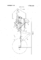
- FIG. 1 is a schematic side elevational view of one type of web rewinding apparatus in which a preferred embodiment of the invention is incorporated;
- FIG. 2 is an enlarged perspective view of the rewind apparatus of FIG. 1 with the web broken away to illustrate the support sheet handling apparatus in a holding position in full lines, and a loading position in broken lines;
- FIG. 3 is a fragmentary perspective view similar to FIG. 2 illustrating the support sheet handling apparatus in a transfer position, in which the support sheet is fed into the nip between the roll and core;
- FIG. 4 is a fragmentary perspective view illustrating the cutting strip severing the web and transferring the leading end of the severed web onto a new core during a transfer operation;
- FIG. 5 (sheet 4 of the drawings) is a top plan view of a support sheet and an embodiment of cutting strip mounted thereon;
- FIG. 6 (sheet 3 of the drawings) is an enlarged view in section taken substantially along line 6-6 of FIG. 5;
- FIG. 7 (sheet 4 of the drawings) is a top plan view of a support sheet onto which is mounted a different embodiment of the cutting strip.
- FIG. 1 of the drawings a preferred embodiment of the invention is illustrated in connection with a known type of rewinding apparatus in which a web 10 is severed to complete a roll 12, and the leading end of the severed web transferred onto a new core 14 to initiate winding of a new roll.
- the rewinding apparatus is generally provided with a housing 16 pivotally mounted on a shaft 18 having a core support means 20 movable to a core latched position by a fluid cylinder 22 for holding new core 14 generally at a transfer station designated A, but out of peripheral engagement with a winding drum 24.
- Web 10 from a paper making machine or the like is fed over guide rollers 26, severed by suitable mechanism and transferred onto new core 14 when it is moved by housing 16 via arm 27, eccentric wheel 28 and cam 30 into engagement with winding drum 24.
- the rotating core 14 and web 10 being wound thereon is moved further along the periphery of winding drum 24 by housing 16 until it reaches a final winding position designated B at which time the core 14 is released and housing 16 returned to its normal position for receiving and holding a new core.
- roll 12 is fully wound at winding station B, the web is severed once again and the severed end transferred onto a new core 14 at station A.
- a roll removing follower arm 32 is pivotally moved by fluid cylinder 34 cuasing spring mounted dog 36 to engage the spindle of the fully wound roll 12 and slide the roll along rails 38 to the broken line position at the unloading station designated C. Since rewinding mechanisms of the aforementioned type are generally old in the art, further specific details of the mechanism will not be described in the specification or disclosed in the drawings.
- the web 10 is trained over guide rollers 26, over winding drum 24 and onto core 14 which has been moved as indicated heretofor by housing 16 and eccentric 28 to the winding position B.
- Core 14 is normally provided with double sided adhesive tape rings, not shown, on its periphery to prevent slippage between the roll 12 and the core during subsequent operations.
- the roll 12 at station B is driven by drum 24, and web 10 wound thereon until it reaches the desired size.
- the web is severed by one of two possible cutting strips 40,40 (FIGS. 2 and 7) fed into the nip formed by new core 14 and drum 24 by a feeding mechanism 41 to be described in detail hereinafter.
- the severing operation completes the old roll, and the severed leading end is transferred to new core 14 previously moved by housing 16 into peripheral engagement with drum 24 at transfer station A.
- the transfer operation is preferably not commenced untilafter new core 14 has been in peripheral engagement with driving drum 24 for a sufficient period of time so that the peripheral speeds of the drum and core are substantially equal. Accordingly,
- the web 10 is severed and the severed leading end transferred onto the new core by one of the cutting strips 40,40 illustrated in FIGS. 5 and 7 respectively.
- the core is longer than the web width, or if the same length, is provided with core extensions so that the core ends extend past the adjacent edges of the web.
- the leading end 42 thereof has a tab portion 44 secured thereto having an adhesive surface facing the core when brought into engagement therewith for adhering to the core end when it is fed into the nip between the core and drum.
- the strip 40 is preferably formed from a polyethylene terephthalate material such as Estar (trademark) or Mylar (trademark) having a tear strength greater than that of the web.
- strip 40 Since polyethylene terephthalate material is relatively slippery, in order to cut the web, it is desirable to adhere strip 40 to web 10 during the transfer operation. This can be achieved by placing a tape 46 (see FIGS. 5 and 6) having an adhesive surface on both sides such as commercially available Scotch (trademark) cellophane tape along the central portion 45 of the cutting strip with one side adhering to the strip and the other side adapted to adhere to web 10 when strip 40 is fed into the nip between core 14 and drum 24.
- a cutting strip 40 of the type illustrated in FIG. 5 is positioned between spaced apart portions of the web and drum, the central portion 45 is arranged in register with web 10 with the leading and trailing ends thereof extending past adjacent edges of the web.
- the tab portion 44 is substantially parallel to the adjacent edge of the web, and when the strip is fed into the nip between the core and drum, the tap portion 44, which extends past the adjacent edge of the web, will wrap partially around new core 14 and adhere thereto preventing the tap portion from tearing away from the core during the high speed transfer operation.
- Strip 40 will sever the web as it follows the curvature of the new core as illustrated in FIG. 4.
- the central portion 45' of the cutting strip is V-shaped and provided with an adhesive tab portion 44 secured to each end thereof. When positioned in a holding position, central portion 45 is substantially in register with the web with the ends thereof extending past adjacent edges of the web.
- the tap portions 44 also extend past the web, and preferably are substantially parallel thereto.
- the cutting strips 40,40 are each initially releasably secured to a preferably flexible support 48 such as a sheet of paper or the like by any suitable means such as a tape or tapes 50,50.
- the tapes each have an adhesive surface on one side in engagement with the central portion 45 of cutting strip 40, and an adhesive surface on the opposite side adhering to support sheet 48.
- the adhesive force with which a cutting strip 40,40 adheres to support sheet 48 is designed to be less than the adhesive force with which the cutting strip adheres to the web when moved into engagement therewith during a transfer operation. Accordingly, the cutting strip 40,40 will pull away from support sheet 48 during the transfer operation.
- support sheet 48 either falls to the ground, or if provided with an adhesive surface on the side of the leading end of the sheet facing the web, will adhere to the trailing end of web 10 on the old roll 12. Also, if support sheet 48 is provided with an adhesive portion on the side of the trailing end of the sheet facing the web, it will releasably attach the end of the old roll to the adjacent roll convolution, and serve to prevent the trailing end of old roll 12 from unwinding. In addition, the transport sheet may be removed from the old roll and reused.
- the cutting strip feeding mechanism 41 for feeding the cutting strip into the nip of core 14 and drum 24 comprises a rectangular table 52 for supporting sheet 48, and confining the sheet on three sides by peripheral lips 54. A third or leading side or edge of the table is unconfined, and a leading edge 56 of support sheet 48 extends a short distance past or overhangs the adjacent leading edge of table 52. Where the sheet is inserted into the nip of core 14 and drum 24, such overhang may be three inches or more in order to prevent table 52 from striking drum 24.
- the table 52 is slidably mounted on an elongated, rectangular bed 58 through complimentary elongated rib and slot guideways 60 for reciprocal movement in a direction laterally of web 10 between a loading position, shown in broken lines in FIG. 2, in which the table is clear of the web and in position to be loaded with a support sheet having a cutting strip, and a holding position, shown in full lines in FIG. 2, in which table 52 is in register with and below web 10.
- the bed 58 is slidably mounted on a rigid frame 62 for reciprocal movement parallel to the web between the holding position and transfer position, as shown in FIG. 3, in which the leading end or edge 56 of support sheet 48 is slowly fed into, or, if desired, rapidly thrown into the nip between core 14 and drum 24.
- frame 62 is shown rigid, it may be arranged to be movably mounted by any suitable means for movement to the holding positions before table 52 can be moved to the loading position.
- the slidable mounting between bed 58 and frame 62 comprises depending flanges 64 on the bed having openings for slidably receiving rods 66 extending between flanges 68 on the frame.
- the leading flanges 68 on frame 62 limit forward travel of bed 58 and table 52 by interference between flanges 64, 68 to a precise transfer position, or the flanges 68 may be provided with adjustable screws, not shown, to provide an adjustable stop engageable by flanges 64.
- the reciprocating motion is imparted to table 52 by any suitable means such as a fluid cylinder 70 controlled by fluid valves connected to a fluid pressure source by flexible tubing 1 or the like.
- a fluid cylinder 70 controlled by fluid valves connected to a fluid pressure source by flexible tubing 1 or the like.
- the operator will also place one of the cutting strips 40,40 on a support sheet 48, laterally move table 52 outwardly clear of web 10 to its loading position, load support sheet 48 on table 52, and return the table to its holding position. In such holding position, the central portion 45,45 of cutting strip 40,40
- the transfer operation is initiated by automatically or manually actuating fluid cylinder 70 causing bed 58 and table 52 to be moved from the holding position to the transfer position for feeding leading end 56 of support sheet 48 into the nip between the core and drum.
- the tab portion 44,44 of cutting strip 40,40 wraps around and adheres to new core 14, and the cutting strip severs web 10 and winds the leading end 72 (FIG. 4) of the severed web onto new core 14 to form a new roll.
- the support sheet 48 either drops off and is discarded, or adheres to the trailing end 74 of the severed web and is wound on the old roll 12.
- the invention is shown in connection with a web rewinding machine of the type illustrated in FIG. 1, it is usable in any type of web winding apparatus in which a new core is movable into peripheral engagement with a web support, fixed or rotatable, over which the web is transported.
- the new core could be moved directly into peripheral engagement with an old roll as it is being wound, and the web then severed to terminate the old roll and initiate winding a new roll on the core.
- a method for severing a web transported over a web support member to terminate formation of a first web roll and transfer the severed leading end onto a rotatable core to form a second web roll comprising the steps of:
- the method according to claim 1 comprising the step of releasably securing the strip to a flexible support sheet prior to the strip positioning step, positioning the sheet and strip at the holding position, and feeding the sheet and strip from said holding position into the nip.
- a web winding apparatus having a rotatable surface for supporting a web fed therein with portions of said surface and web spaced apart from one another, a rotatable core engageable by said web supporting surface and adapted to have a new roll wound thereon, the combination comprising:
- a web winding apparatus having a rotatable web driving drum over which the web is fed with portions of said drum and web spaced apart from one another, and wound onto a rotatable first core to form a first web roll, and a rotatable second core onto which the web is wound to form a second roll, said second core bieng movable into peripheral engagement with said driving drum and web thereon to form a nip therebetween, the combination comprising:
- strip supporting means comprises a flexible sheet to which said strip is releasably secured, and a table for supporting said flexible sheet.
- strip supporting means comprises a flexible sheet to which said strip is releasably secured, and a table for supporting said flexible sheet
- strip feeding means comprises means for moving said table toward said nip from said holding position to a transfer position, in which said sheet and strip are fed into said nip.
- said tab portion of said strip extends beyond the adjacent edge of the web and has adhesive on the surface facing said second core, and said central portion is substantially in register with the web and arranged at an angle to said nip, said central portion further being formed of polyethylene terephthalate to which a first tape having adhesive on each side thereof is releasably secured to the surface of said central portion facing the web, and a second tape having adhesive on each side thereof is releasably secured to the opposite surface of said central portion.
- said strip supporting means comprises a flexible sheet, and a table for supporting said flexible sheet
- said strip feeding means comprises means for moving said table toward said nip from said holding position to a transfer position, in which said sheet and strip are fed into said nip,- and wherein said tab portion of said strip extends beyond the adjacent edge of the web and has adhesive on the surface facing said second core, and said central portion is substantially in register with said web and arranged at an angle to said nip, said central portion further being formed of polyethylene terephthalate and having a first tape having adhesive on each side thereof with one adhesive side releasably secured to the surface of the central portion facing the web, and a second tape having adhesive on each side therof releasably secured to the opposite surface of the central portion for releasably securing said strip to said flexible sheet, and said adhesive strength of the other adhesive side of said one tape facing said web is greater than the adhesive strength with which said second tape secures said strip to said flexible sheet.
Abstract
A core onto which a web is to be wound is adapted to be moved into peripheral engagement with one side of a web support such as a winding drum or roll over which the web passes. A cutting strip of polymethylene terephthalate is positioned between spaced portions of the web and roll, and has a central portion in register with the web and inclined at an angle to the nip of the core and roll. A tape having an adhesive surface on both sides is placed on the surface of the central portion of the strip facing the web. The strip has leading and trailing end portions extending beyond respective adjacent edges of the web, and an adhesive tab portion secured to the leading end portion. When the speed of the core substantially matches the speed of the roll, the strip is fed beneath the web directly into the nip formed by the rotating roll and core. The adhesive tab portion of the strip adheres to the core end extending past the adjacent edge of the web causing the central portion of the strip, as it passes through the nip, to adhere to the web and sever it. The central portion and leading end of the severed web are wound onto the core along with the tab portion.
Description
United States Patent [191 Brink et al.
[451 Oct. 16, 1973 [75] Inventors: Walter A. Brink; Thomas G.
Hanley, both of Rochester, N.Y.
[73] Assignee: Eastman Kodak Company,
Rochester, N.Y.
22 Filed: May 30,1972
21 Appl. No.: 257,613
[52] US. Cl. 242/56 R, 242/74 [51] Int. Cl B65h 19/26, B65h l9/28 [58] Field of Search 242/56 R, 58.5, 64,
[56] References Cited UNITED STATES PATENTS 8/1971 Coudrief 292/64 3/1939 Bernard 2/1949 Weyenberg 242/56 R Primary Examiner-George F. Mautz Assistant ExaminerEdward J. McCarthy Attorney-William T. French et a].
[5 7] ABSTRACT A core onto which a web is to be wound is adapted to be moved into peripheral engagement with one side of a web support such as a winding drum or roll over which the web passes. A cutting strip of polymethylene terephthalate is positioned between spaced portions of the web and roll, and has a central portion in register with the web and inclined at an angle to the nip of the core and roll. A tape having an adhesive surface on both sides is placed on the surface of the central portion of the strip facing the web. The strip has leading and trailing end portions extending beyond respective adjacent edges of the web, and an adhesive tab portion secured to the leading end portion. When the speed of the core substantially matches the speed of the roll, the strip is fed beneath the web directly into the nip formed by the rotating roll and core. The adhesive tab portion of the strip adheres to the core end extending past the adjacent edge of the web causing the central portion of the strip, as it passes through the nip, to adhere to the web and sever it. The central portion and leading end of the severed web are wound onto the core along with the tab portion.
20 Claims, 7 Drawing Figures PATENTED EU 1 6-1975 SHEET H []F 4 METHOD AND APPARATUS FOR SEVERING A WEB TO TERMINATE ONE ROLL AND INITIATE WINDING A NEW ROLL BACKGROUND OF THE INVENTION 1. Field of the Invention This invention relates generally to the winding of webs into rolls, and more specifically to an improved method and apparatus for severing a web to terminate one roll, and to transfer the leading end of the severed web onto a new roll core without stopping the machine.
2. Description of the Prior Art Methods and apparatus for severing web material upon completion of winding of one roll and initiating winding of a new roll without stopping the machine are generally well known in the art. One such method involves applying an adhesive surface to the core upon which the new roll is to be wound, moving the core into engagement with the web and a web driving drum, and slashing or nicking one edge of the web to produce a flap or tap which, hopefully, will adhere to the new core. If the tab portion adheres to the new core, it will wind onto the core, hopefully tearing the web across its entire width. More frequently than not, however, the web tears longitudinally rather than transversely, necessitating stopping the machine and severing portions from the trailing end of the old web and the leading end of the new web. Accordingly, this known method is unreliable and costly due to waste of time and paper.
Another mechanism for severing a web on completion of one roll and initiating winding of a new roll without stopping the machine is known throughout the paper industry as the Pope Reel. One form of this reel is described in US. Pat. No. 1,248,542, and generally comprises a driving drum over which the web is moved, and a new core which is moved into peripheral engagement with the drum and driven thereby. The web is severed along a line just beyond the new core, and the leading edge thus formed is directed upwardly and around the core. The directing of the web may be accomplished by jets of air, water or steam, or may be accomplished by mechanical manipulation. One form of such mechanical manipulation is disclosed in U. S. Pat. No. 2,461,246, and involves a cutting strip of felt or the like having one end secured to a spring clip adjacent one edge of the web, and a central portion of the strip trained over the new core adjacent the opposite edge of the web. To initiate severing the web and transferring the leading edge thus formed onto the new core, the other end of the cutting strip is wound on a pulley by a motor causing the strip to move across the web severing the web and winding it onto the new roll. Similar mechanisms are also disclosed in U. S. Pat. Nos. 2,343,047 and 3,096,947 utilizing a cutting wire in which one end of the wire adjacent one edge of the web is releasably held, and the opposite end of the wire adjacent the opposite edge of the web is attachable to a new core by a hook or the like. Still another method and apparatus is disclosed in U. S. Pat. No. 3,599,888, in which a strip of adhesive tape is used instead of a cutting wire. A trailing portion of the tape is wound helically on a rotatable tape bar adjacent to and in register with the web, and the leading portion of the tape is manually secured to a new core prior to engagement of the core with the winding drum. Accordingly, when the core engages the winding drum and is rotated thereby, the trailing portion of the tape is released from the tape bar, adheres to the web, severs the web as it passes through the nip between the core and drum, and winds the leading end of the severed web onto the core. One disadvantage of such latter method and apparatus is the necessity to manually adhere the leading end of the tape to the new core. Furthermore, due to the difference in speed between the new core and the web when the core is brought into engagement therewith during the transfer operation, crimping or creasing of the lead end of the web occurs as it is wound on the new core. Such creasing distorts and hence damages subsequent convolutions of web as they are wound on the core until a sufficient number of convolutions are wound to smooth out the distortion. The number of feet of web damaged by such distortions may be considerable, varying with the severity of the creases and the characteristics of the web. For example, a 2 mil web would produce considerably more impression waste from a crease than a stiffer 10 mil web. Applicants invention is believed to obviate these and other disadvantages of such prior art methods and apparatus for severing a web to terminate one roll, and transferring the leading end of the severed web onto a new roll.
SUMMARY OF THE INVENTION In accordance with a preferred embodiment of the invention, an improved and apparatus is provided for severing a web to terminate one roll, and transferring the leading end of the severed web onto a core to form a new roll. Such improved method essentially comprises moving a core onto which the new roll is to be wound into peripheral engagement with a rotatable web support to form a nip therebetween through which the web is transported. The core is wider than the web width with ends or extensions thereon extending past the adjacent edges of the web. A cutting strip having a tear strength greater than that of the web is placed in a holding position between spaced apart portions of the web and roll, and has a central portion in register with the web surface facing the roll, and inclined at an angle to the nip of the core and roll. The cutting strip is arranged to have leading and trailing end portions extending beyond the adjacent edges respectively of the web, and an adhesive tap portion secured to the leading end portion. The cutting strip is moved from the holding position to a transfer position in which it is fed directly into the nip causing the adhesive tab portion to adhere to the core end or extension, and the strip to sever the web and to transfer the leading end of the severed web onto the core.
A preferred embodiment of a cutting strip handling apparatus for releasably holding a cutting strip, and moving it into the nip of the roll and core comprises a table for releasably supporting a cutting strip support sheet with the leading end of the sheet extending beyond the leading edge of the table. The table is slidably mounted on a bed for reciprocal movement in a direction laterally of the web between a loading position, in which the table is clear of the web and in position to be loaded with a support sheet having a cutting strip, and a holding position in which the table is spaced from and in register with the web. The bed is also slidably mounted on a rigid frame for reciprocal movement longitudinally of the web between the holding position and a transfer position, in which the leading end of the support sheet is slowly inserted or thrown into the nip between the core and roll.
It is, therefore, one of the objects of the present invention to provide an improved method and apparatus for terminating the formation of a web roll by severing the web, and transferring the leading end of the severed web onto a core to form a new roll.
Another object of the invention is to provide an improved method for terminating the formation of one web roll and initiating the winding of a new roll that minimizes loss of time and wastage of paper during the transfer operation.
Another object of the invention is to provide an improved method and apparatus for terminating one roll and initiating the winding of a new roll that avoids manual manipulation of a cutting strip by the operator during the transfer operation, and hence the likelihood of operator injury.
Another object of the invention is to provide an improved method and apparatus for terminating the winding of a web on one roll, and initiating the winding of a new roll, in which the transfer operation is more accurately and precisely initiated and terminated than heretofore.
Another object of the invention is to provide an improved method and apparatus for terminating the winding of a web on one roll and initiating the winding of a new roll in which a support sheet used in the transfer operation releasably attaches the end of the old roll to the adjacent roll convolution.
Another object of the invention is to provie an improved method and apparatus for terminating the wind ing of a web on one roll and initiating the winding of a new roll that is of simple design and construction, thoroughly reliable and efficient in operation, and economical to manufacture.
The invention and its objects and advantages will become more apparent from the detailed description of the preferred embodiment presented below.
BRIEF DESCRIPTION OF THE DRAWINGS In the detailed description of the preferred embodiment of the invention presented below, reference is made to the accompaning drawings, in which:
FIG. 1 is a schematic side elevational view of one type of web rewinding apparatus in which a preferred embodiment of the invention is incorporated;
FIG. 2 is an enlarged perspective view of the rewind apparatus of FIG. 1 with the web broken away to illustrate the support sheet handling apparatus in a holding position in full lines, and a loading position in broken lines;
FIG. 3 is a fragmentary perspective view similar to FIG. 2 illustrating the support sheet handling apparatus in a transfer position, in which the support sheet is fed into the nip between the roll and core;
FIG. 4 is a fragmentary perspective view illustrating the cutting strip severing the web and transferring the leading end of the severed web onto a new core during a transfer operation;
FIG. 5 (sheet 4 of the drawings) is a top plan view of a support sheet and an embodiment of cutting strip mounted thereon;
FIG. 6 (sheet 3 of the drawings) is an enlarged view in section taken substantially along line 6-6 of FIG. 5; and
FIG. 7 (sheet 4 of the drawings) is a top plan view of a support sheet onto which is mounted a different embodiment of the cutting strip.
DESCRIPTION OF THE PREFERRED EMBODIMENTS Because web winding mechanisms are well known, the present description will be directed in particular to elements forming part of, or cooperating more directly with, the apparatus of the present invention. Elements of web winding mechanisms not specifically shown or described herein should be understood to be selectable from those known in the art.
With reference to FIG. 1 of the drawings, a preferred embodiment of the invention is illustrated in connection with a known type of rewinding apparatus in which a web 10 is severed to complete a roll 12, and the leading end of the severed web transferred onto a new core 14 to initiate winding of a new roll. The rewinding apparatus is generally provided with a housing 16 pivotally mounted on a shaft 18 having a core support means 20 movable to a core latched position by a fluid cylinder 22 for holding new core 14 generally at a transfer station designated A, but out of peripheral engagement with a winding drum 24. Web 10 from a paper making machine or the like is fed over guide rollers 26, severed by suitable mechanism and transferred onto new core 14 when it is moved by housing 16 via arm 27, eccentric wheel 28 and cam 30 into engagement with winding drum 24. The rotating core 14 and web 10 being wound thereon is moved further along the periphery of winding drum 24 by housing 16 until it reaches a final winding position designated B at which time the core 14 is released and housing 16 returned to its normal position for receiving and holding a new core. When roll 12 is fully wound at winding station B, the web is severed once again and the severed end transferred onto a new core 14 at station A. A roll removing follower arm 32 is pivotally moved by fluid cylinder 34 cuasing spring mounted dog 36 to engage the spindle of the fully wound roll 12 and slide the roll along rails 38 to the broken line position at the unloading station designated C. Since rewinding mechanisms of the aforementioned type are generally old in the art, further specific details of the mechanism will not be described in the specification or disclosed in the drawings.
During a normal web rewinding operation of the aforementioned rewinding apparatus in which the structure of this invention is incorporated, the web 10 is trained over guide rollers 26, over winding drum 24 and onto core 14 which has been moved as indicated heretofor by housing 16 and eccentric 28 to the winding position B. Core 14 is normally provided with double sided adhesive tape rings, not shown, on its periphery to prevent slippage between the roll 12 and the core during subsequent operations. The roll 12 at station B is driven by drum 24, and web 10 wound thereon until it reaches the desired size. When this occurs, the web is severed by one of two possible cutting strips 40,40 (FIGS. 2 and 7) fed into the nip formed by new core 14 and drum 24 by a feeding mechanism 41 to be described in detail hereinafter. The severing operation completes the old roll, and the severed leading end is transferred to new core 14 previously moved by housing 16 into peripheral engagement with drum 24 at transfer station A. The transfer operation is preferably not commenced untilafter new core 14 has been in peripheral engagement with driving drum 24 for a sufficient period of time so that the peripheral speeds of the drum and core are substantially equal. Accordingly,
when the transfer is made, slippage between the new core 14 and web is minimized resulting in minimal creasing or distortion of the web as it is wound onto the core.
As indicated earlier, the web 10 is severed and the severed leading end transferred onto the new core by one of the cutting strips 40,40 illustrated in FIGS. 5 and 7 respectively. The core is longer than the web width, or if the same length, is provided with core extensions so that the core ends extend past the adjacent edges of the web. With regard to strip 40, the leading end 42 thereof has a tab portion 44 secured thereto having an adhesive surface facing the core when brought into engagement therewith for adhering to the core end when it is fed into the nip between the core and drum. The strip 40 is preferably formed from a polyethylene terephthalate material such as Estar (trademark) or Mylar (trademark) having a tear strength greater than that of the web. Since polyethylene terephthalate material is relatively slippery, in order to cut the web, it is desirable to adhere strip 40 to web 10 during the transfer operation. This can be achieved by placing a tape 46 (see FIGS. 5 and 6) having an adhesive surface on both sides such as commercially available Scotch (trademark) cellophane tape along the central portion 45 of the cutting strip with one side adhering to the strip and the other side adapted to adhere to web 10 when strip 40 is fed into the nip between core 14 and drum 24. When a cutting strip 40 of the type illustrated in FIG. 5 is positioned between spaced apart portions of the web and drum, the central portion 45 is arranged in register with web 10 with the leading and trailing ends thereof extending past adjacent edges of the web. The tab portion 44 is substantially parallel to the adjacent edge of the web, and when the strip is fed into the nip between the core and drum, the tap portion 44, which extends past the adjacent edge of the web, will wrap partially around new core 14 and adhere thereto preventing the tap portion from tearing away from the core during the high speed transfer operation. Strip 40 will sever the web as it follows the curvature of the new core as illustrated in FIG. 4. In the cutting strip 40' shown in FIG. 7, the central portion 45' of the cutting strip is V-shaped and provided with an adhesive tab portion 44 secured to each end thereof. When positioned in a holding position, central portion 45 is substantially in register with the web with the ends thereof extending past adjacent edges of the web. The tap portions 44 also extend past the web, and preferably are substantially parallel thereto.
The cutting strips 40,40, as best seen in FIGS. 5 and 7, are each initially releasably secured to a preferably flexible support 48 such as a sheet of paper or the like by any suitable means such as a tape or tapes 50,50. The tapes each have an adhesive surface on one side in engagement with the central portion 45 of cutting strip 40, and an adhesive surface on the opposite side adhering to support sheet 48. The adhesive force with which a cutting strip 40,40 adheres to support sheet 48 is designed to be less than the adhesive force with which the cutting strip adheres to the web when moved into engagement therewith during a transfer operation. Accordingly, the cutting strip 40,40 will pull away from support sheet 48 during the transfer operation. When this occurs, support sheet 48 either falls to the ground, or if provided with an adhesive surface on the side of the leading end of the sheet facing the web, will adhere to the trailing end of web 10 on the old roll 12. Also, if support sheet 48 is provided with an adhesive portion on the side of the trailing end of the sheet facing the web, it will releasably attach the end of the old roll to the adjacent roll convolution, and serve to prevent the trailing end of old roll 12 from unwinding. In addition, the transport sheet may be removed from the old roll and reused.
The cutting strip feeding mechanism 41, as best seen in FIG. 2, for feeding the cutting strip into the nip of core 14 and drum 24 comprises a rectangular table 52 for supporting sheet 48, and confining the sheet on three sides by peripheral lips 54. A third or leading side or edge of the table is unconfined, and a leading edge 56 of support sheet 48 extends a short distance past or overhangs the adjacent leading edge of table 52. Where the sheet is inserted into the nip of core 14 and drum 24, such overhang may be three inches or more in order to prevent table 52 from striking drum 24. The table 52 is slidably mounted on an elongated, rectangular bed 58 through complimentary elongated rib and slot guideways 60 for reciprocal movement in a direction laterally of web 10 between a loading position, shown in broken lines in FIG. 2, in which the table is clear of the web and in position to be loaded with a support sheet having a cutting strip, and a holding position, shown in full lines in FIG. 2, in which table 52 is in register with and below web 10. The bed 58 is slidably mounted on a rigid frame 62 for reciprocal movement parallel to the web between the holding position and transfer position, as shown in FIG. 3, in which the leading end or edge 56 of support sheet 48 is slowly fed into, or, if desired, rapidly thrown into the nip between core 14 and drum 24. Although frame 62 is shown rigid, it may be arranged to be movably mounted by any suitable means for movement to the holding positions before table 52 can be moved to the loading position. The slidable mounting between bed 58 and frame 62 comprises depending flanges 64 on the bed having openings for slidably receiving rods 66 extending between flanges 68 on the frame. The leading flanges 68 on frame 62 limit forward travel of bed 58 and table 52 by interference between flanges 64, 68 to a precise transfer position, or the flanges 68 may be provided with adjustable screws, not shown, to provide an adjustable stop engageable by flanges 64. The reciprocating motion is imparted to table 52 by any suitable means such as a fluid cylinder 70 controlled by fluid valves connected to a fluid pressure source by flexible tubing 1 or the like. By properly adjusting and regulating the ratus and move the core through housing 16 and related apparatus into peripheral engagement with winding drum 24. The operator will also place one of the cutting strips 40,40 on a support sheet 48, laterally move table 52 outwardly clear of web 10 to its loading position, load support sheet 48 on table 52, and return the table to its holding position. In such holding position, the central portion 45,45 of cutting strip 40,40
respectively is substantially in register with web 10 and inclined at an angle to the nip of core 14 and drum 24. Applicants have found that an angle of 6 provides satisfactory results, but any other suitable angle may be used. The leading and trailing ends of central portions 45,45 extend past the adjacent edges of web 10, and the tab portion 44,44 is substantially parallel to the adjacent edge of the web. The order of performance of the foregoing operations of loading a new core and cutting strip may vary depending upon various circumstances. When the core 14 has been moved into peripheral engagement with drum 24, and the peripheral speeds of the core and drum are substantially equal, the transfer operation is initiated by automatically or manually actuating fluid cylinder 70 causing bed 58 and table 52 to be moved from the holding position to the transfer position for feeding leading end 56 of support sheet 48 into the nip between the core and drum. The tab portion 44,44 of cutting strip 40,40 wraps around and adheres to new core 14, and the cutting strip severs web 10 and winds the leading end 72 (FIG. 4) of the severed web onto new core 14 to form a new roll. The support sheet 48 either drops off and is discarded, or adheres to the trailing end 74 of the severed web and is wound on the old roll 12.
Although the invention is shown in connection with a web rewinding machine of the type illustrated in FIG. 1, it is usable in any type of web winding apparatus in which a new core is movable into peripheral engagement with a web support, fixed or rotatable, over which the web is transported. For example, the new core could be moved directly into peripheral engagement with an old roll as it is being wound, and the web then severed to terminate the old roll and initiate winding a new roll on the core.
The invention has been described in detail with particular reference to preferred embodiments thereof, but it will be understood that variations and modifications can be effected within the spirit and scope of the invention as described hereinabove.
I claim:
1. A method for severing a web transported over a web support member to terminate formation of a first web roll and transfer the severed leading end onto a rotatable core to form a second web roll, comprising the steps of:
moving said core and said web support member relative to one another into peripheral pressure engagement to form a nip through which the web passes;
rotatably driving said core;
positioning a strip having a tear strength greater than that of the web in a holding position between spaced portions of the web and said web support member, with a leading portion of the strip having an adhesive surface facing said core and extending beyond an adjacent edge of the web, and a central portion of the strip substantially in register with the web and arranged at an angle to said nip; and
feeding said strip from said holding position to a transfer position in which said strip enters directly into said nip whereby the leading adhesive portion adheres to said rotating core and said central portion severs the web along the leading edge of said central portion and winds the leading end of the severed web and said central portion onto said core.
2. The method according to claim 1 comprising arranging the leading adhesive portion substantially parallel to said adjacent edge of the web.
3. The method according to claim 1 comprising forming the central portion of the strip of polyethylene terephthalate material of one width, and adhering to the surface of said central portion facing the web a tape of a width no greater than said one width and having adhesive on each side thereof.
4. The method according to claim 1 comprising the step of releasably securing the strip to a flexible support sheet prior to said strip positioning step.
5. The method according to claim 1 comprising the step of releasably securing the strip to a flexible support sheet prior to the strip positioning step, positioning the sheet and strip at the holding position, and feeding the sheet and strip from said holding position into the nip.
6. The method according to claim 1 comprising extending the central portion across the full width of the web.
7. The method according to claim 1 comprising forming said strip with ends extending past the adjacent edges of the web in said holding position, and a V- shaped portion substantially in register with the web and arranged at an angle to the nip.
8. The invention according to claim 1 wherein said web support member is rotatable, and further including the step of delaying th strip feeding step until the peripheral speeds of said web support member and core are substantially equal.
9. In a web winding apparatus having a rotatable surface for supporting a web fed therein with portions of said surface and web spaced apart from one another, a rotatable core engageable by said web supporting surface and adapted to have a new roll wound thereon, the combination comprising:
means for releasably supporting a web severing strip in a holding position between spaced apart portions of the web and said web supporting surface and adjacent the nip formed between said web supporting surface and core; and
means separate from said core for feeding said strip substantially directly into said nip whereby the leading end of said strip adheres to and is wound on said core causing said strip to sever the web and to wind the leading end of the severed web onto said core.
10. The invention according to claim 9 wherein said web supporting surface is a winding drum.
11. In a web winding apparatus having a rotatable web driving drum over which the web is fed with portions of said drum and web spaced apart from one another, and wound onto a rotatable first core to form a first web roll, and a rotatable second core onto which the web is wound to form a second roll, said second core bieng movable into peripheral engagement with said driving drum and web thereon to form a nip therebetween, the combination comprising:
means for releasably supporting a web severing strip in a holding position between spaced apart portions of said web and drum and adjacent said nip, said strip having a tab portion extending past an adjacent edge of the web, and a central portion substantially in register with the web, said tab and central portions having at least one adhesive surface on one side thereof; and
means separate from said core for feeding said strip substantially directly into said nip with a minimum of engagement of the web or said second core whereby the tab portion of said strip adheres to and is wound on said second core, and said central portion adheres to the web causing said strip to sever the web and to wind the leading end of the severed web onto said second core.
12. The invention according to claim 11 wherein said tab portion of said strip is substantially parallel to said adjacent edge of the web, and said central portion of said strip extends across the full width of the web.
13. The invention according to claim 1 1 wherein said strip has tab portions at each end, and a V-shaped central portion interposed between and connected to said tab portions.
14. The invention according to claim 11 wherein said tab portions extend beyond respective adjacent edges of the web, and are substantially parallel to said adjacent edges of the web, and said V-shaped central portion is in register with and extends across the web.
15. The invention according to claim 11 wherein said strip supporting means comprises a flexible sheet to which said strip is releasably secured, and a table for supporting said flexible sheet.
16. The invention according to claim 1 1 wherein said strip supporting means comprises a flexible sheet to which said strip is releasably secured, and a table for supporting said flexible sheet, and said strip feeding means comprises means for moving said table toward said nip from said holding position to a transfer position, in which said sheet and strip are fed into said nip.
17. The invention according to claim 11 wherein said tab portion of said strip has adhesive on the surface facing said second core, and said central portion of said strip is formed of polyethylene terephthalate, and a tape having adhesive on each side thereof is releasably secured to the surface of said central portion facing the web.
18. The invention according to claim 11 wherein said tab portion of said strip extends beyond the adjacent edge of the web and has adhesive on the surface facing said second core, and said central portion is substantially in register with the web and arranged at an angle to said nip, said central portion further being formed of polyethylene terephthalate to which a first tape having adhesive on each side thereof is releasably secured to the surface of said central portion facing the web, and a second tape having adhesive on each side thereof is releasably secured to the opposite surface of said central portion.
19. The invention according to claim 18 wherein the adhesive strength with which said tape on the surface of said central portion facing the web adheres to said central portion is greater than the adhesive strength with which said tape on the opposite surface of said central portion adheres to said strip supporting means.
20. The invention according to claim 11 wherein said strip supporting means comprises a flexible sheet, and a table for supporting said flexible sheet, said strip feeding means comprises means for moving said table toward said nip from said holding position to a transfer position, in which said sheet and strip are fed into said nip,- and wherein said tab portion of said strip extends beyond the adjacent edge of the web and has adhesive on the surface facing said second core, and said central portion is substantially in register with said web and arranged at an angle to said nip, said central portion further being formed of polyethylene terephthalate and having a first tape having adhesive on each side thereof with one adhesive side releasably secured to the surface of the central portion facing the web, and a second tape having adhesive on each side therof releasably secured to the opposite surface of the central portion for releasably securing said strip to said flexible sheet, and said adhesive strength of the other adhesive side of said one tape facing said web is greater than the adhesive strength with which said second tape secures said strip to said flexible sheet.
@2333? UNITED STATES PATENT OFFICE- e CERTIFICATE OF CORRECTION Patent No. 3,765,615 Dated October 16, 1973 f fl Walter A. Brink and Thomas G; Hanley It is certified that error appears in the above-identified patent and that said Letters Patent are hereby corrected as shown below:
Column: 2, line 27, after "improved" insert-method".
In the ABSTRACT line 5', delete "polymethylene and ins'ert--p"olyethylene--.
- Signed and sealed this 13th day of August 1974.
SEAL) Attest: I McCOY M. GIBSON, -JR. -c. MARSHALL DANN Attesting Officer Commissioner of Patents
Claims (20)
1. A method for severing a web transported over a web support member to terminate formation of a first web roll and transfer the severed leading end onto a rotatable core to form a second web roll, comprising the steps of: moving said core and said web support member relative to one another into peripheral pressure engagement to form a nip through which the web passes; rotatably driving said core; positioning a strip having a tear strength greater than that of the web in a holding position between spaced portions of the web and said web support member, with a leading portion of the strip having an adhesive surface facing said core and extending beyond an adjacent edge of the web, and a central portion of the strip substantially in register with the web and arranged at an angle to said nip; and feeding said strip from said holding position to a transfer position in which said strip enters directly into said nip whereby the leading adhesive portion adheres to said rotating core and said central portion severs the web along the leading edge of said central portion and winds the leading end of the severed web and said central portion onto said core.
2. The method according to claim 1 comprising arranging the leading adhesive portion substantially parallel to said adjacent edge of the web.
3. The method according to claim 1 comprising forming the central portion of the strip of polyethylene terephthalate material of one width, and adhering to the surface of said central portion facing the web a tape of a width no greater than said one width and having adhesive on each side thereof.
4. The method according to claim 1 comprising the step of releasably securing the strip to a flexible support sheet prior to said strip positioning step.
5. The method according to claim 1 comprising the step of releasably securing the strip to a flexible support sheet prior to the strip positioning step, positioning the sheet and strip at the holding position, and feeding the sheet and strip from said holding position into the nip.
6. The method according to claim 1 comprising extending the central portion across the full width of the web.
7. The method according to claim 1 comprising forming said strip with ends extending past the adjacent edges of the web in said holding position, and a V-shaped portion substantially in register with the web and arranged at an angle to the nip.
8. The invention according to claim 1 wherein said web support member is rotatable, and further including the step of delaying th strip feeding step until the peripheral speeds of said web support member and core are substantially equal.
9. In a web winding apparatus having a rotatable surface for supporting a web fed therein with portions of said surface and web spaced apart from one another, a rotatable core engageable by said web supporting surface and adapted to have a new roll wound thereon, the combination comprising: means for releasably supporting a web severing strip in a holding position between spaced apart portions of the web and said web supporting surface and adjacent the nip formed between said web supporting surface and core; and means separate from said core for feeding said strip substantially directly into said nip whereby the leading end of said strip adheres to and is wound on said core causing said strip to seveR the web and to wind the leading end of the severed web onto said core.
10. The invention according to claim 9 wherein said web supporting surface is a winding drum.
11. In a web winding apparatus having a rotatable web driving drum over which the web is fed with portions of said drum and web spaced apart from one another, and wound onto a rotatable first core to form a first web roll, and a rotatable second core onto which the web is wound to form a second roll, said second core bieng movable into peripheral engagement with said driving drum and web thereon to form a nip therebetween, the combination comprising: means for releasably supporting a web severing strip in a holding position between spaced apart portions of said web and drum and adjacent said nip, said strip having a tab portion extending past an adjacent edge of the web, and a central portion substantially in register with the web, said tab and central portions having at least one adhesive surface on one side thereof; and means separate from said core for feeding said strip substantially directly into said nip with a minimum of engagement of the web or said second core whereby the tab portion of said strip adheres to and is wound on said second core, and said central portion adheres to the web causing said strip to sever the web and to wind the leading end of the severed web onto said second core.
12. The invention according to claim 11 wherein said tab portion of said strip is substantially parallel to said adjacent edge of the web, and said central portion of said strip extends across the full width of the web.
13. The invention according to claim 11 wherein said strip has tab portions at each end, and a V-shaped central portion interposed between and connected to said tab portions.
14. The invention according to claim 11 wherein said tab portions extend beyond respective adjacent edges of the web, and are substantially parallel to said adjacent edges of the web, and said V-shaped central portion is in register with and extends across the web.
15. The invention according to claim 11 wherein said strip supporting means comprises a flexible sheet to which said strip is releasably secured, and a table for supporting said flexible sheet.
16. The invention according to claim 11 wherein said strip supporting means comprises a flexible sheet to which said strip is releasably secured, and a table for supporting said flexible sheet, and said strip feeding means comprises means for moving said table toward said nip from said holding position to a transfer position, in which said sheet and strip are fed into said nip.
17. The invention according to claim 11 wherein said tab portion of said strip has adhesive on the surface facing said second core, and said central portion of said strip is formed of polyethylene terephthalate, and a tape having adhesive on each side thereof is releasably secured to the surface of said central portion facing the web.
18. The invention according to claim 11 wherein said tab portion of said strip extends beyond the adjacent edge of the web and has adhesive on the surface facing said second core, and said central portion is substantially in register with the web and arranged at an angle to said nip, said central portion further being formed of polyethylene terephthalate to which a first tape having adhesive on each side thereof is releasably secured to the surface of said central portion facing the web, and a second tape having adhesive on each side thereof is releasably secured to the opposite surface of said central portion.
19. The invention according to claim 18 wherein the adhesive strength with which said tape on the surface of said central portion facing the web adheres to said central portion is greater than the adhesive strength with which said tape on the opposite surface of said central portion adheres to said strip supporting means.
20. The invention according to claim 11 wherein said strip supporting means comprises a flexible sheet, and a table for supporting said flexible sheet, said strip feeding means comprises means for moving said table toward said nip from said holding position to a transfer position, in which said sheet and strip are fed into said nip, and wherein said tab portion of said strip extends beyond the adjacent edge of the web and has adhesive on the surface facing said second core, and said central portion is substantially in register with said web and arranged at an angle to said nip, said central portion further being formed of polyethylene terephthalate and having a first tape having adhesive on each side thereof with one adhesive side releasably secured to the surface of the central portion facing the web, and a second tape having adhesive on each side therof releasably secured to the opposite surface of the central portion for releasably securing said strip to said flexible sheet, and said adhesive strength of the other adhesive side of said one tape facing said web is greater than the adhesive strength with which said second tape secures said strip to said flexible sheet.
Applications Claiming Priority (1)
| Application Number | Priority Date | Filing Date | Title |
|---|---|---|---|
| US25761372A | 1972-05-30 | 1972-05-30 |
Publications (1)
| Publication Number | Publication Date |
|---|---|
| US3765615A true US3765615A (en) | 1973-10-16 |
Family
ID=22977004
Family Applications (1)
| Application Number | Title | Priority Date | Filing Date |
|---|---|---|---|
| US00257613A Expired - Lifetime US3765615A (en) | 1972-05-30 | 1972-05-30 | Method and apparatus for severing a web to terminate one roll and initiate winding a new roll |
Country Status (8)
| Country | Link |
|---|---|
| US (1) | US3765615A (en) |
| JP (1) | JPS5647101B2 (en) |
| BE (1) | BE800329A (en) |
| CA (1) | CA995195A (en) |
| DE (1) | DE2326854A1 (en) |
| FR (1) | FR2186939A5 (en) |
| GB (1) | GB1432044A (en) |
| IT (1) | IT988753B (en) |
Cited By (22)
| Publication number | Priority date | Publication date | Assignee | Title |
|---|---|---|---|---|
| WO1986000282A1 (en) * | 1984-06-20 | 1986-01-16 | Rodriguez Peter A | Apparatus and method for cutting and spooling a web of paper |
| US4711404A (en) * | 1985-05-02 | 1987-12-08 | Valmet-KMW Aktiebolag | Apparatus for cutting a paper web |
| US4749139A (en) * | 1986-04-17 | 1988-06-07 | Valmet-Ahlstrom Inc. | Apparatus for severing a web |
| US4757950A (en) * | 1987-08-21 | 1988-07-19 | Sandar Industries, Inc. | Apparatus and method for cutting and spooling a web of paper |
| US4783018A (en) * | 1987-08-21 | 1988-11-08 | Sandar Industries, Inc. | Apparatus and method for cutting and spooling a web of paper |
| US4798350A (en) * | 1987-05-29 | 1989-01-17 | Magna-Graphics Corporation | Web rewind apparatus with cutless web transfer |
| WO1989001454A1 (en) * | 1987-08-21 | 1989-02-23 | Rodriguez Peter A | System and method for cutting and spooling a web of paper |
| US5046675A (en) * | 1989-03-02 | 1991-09-10 | Rodriguez Peter A | System and method for cutting and spooling a web of paper |
| US5467937A (en) * | 1993-11-15 | 1995-11-21 | Sandar Industries, Inc. | Track assembly for a cutting tape |
| US5857641A (en) * | 1997-06-03 | 1999-01-12 | Kimberly-Clark Worldwide, Inc. | Winding core having integral entangling mechanism |
| EP0915048A2 (en) * | 1997-11-04 | 1999-05-12 | Klaus Bartelmuss | Device for dividing a paper web |
| US6076761A (en) * | 1997-06-24 | 2000-06-20 | Bartelmuss; Klaus | Apparatus for severing a paper web |
| US6416012B1 (en) | 1999-02-25 | 2002-07-09 | M.A. Industries, Inc. | Apparatuses and methods for cutting and spooling paper |
| US20040061021A1 (en) * | 2002-09-27 | 2004-04-01 | Butterworth Tad T. | Rewinder apparatus and method |
| US20040131825A1 (en) * | 2003-01-08 | 2004-07-08 | Sdf Group, Llc | Various banding apparatus and methods for using such |
| US20040194595A1 (en) * | 2003-01-23 | 2004-10-07 | Wilmoth Bryan Nathan | Systems, apparatuses and methods for cutting and spooling paper |
| US20050077414A1 (en) * | 2002-02-18 | 2005-04-14 | Voith Paper Patent Gmbh | Element for transferring a moving web onto a core, and method for its use |
| EP1555230A1 (en) * | 2004-01-15 | 2005-07-20 | Sonoco Development, Inc. | Dual-functioning mechanism for startup during winding of web material and for splicing during unwinding |
| US7175127B2 (en) | 2002-09-27 | 2007-02-13 | C.G. Bretting Manufacturing Company, Inc. | Rewinder apparatus and method |
| US20070068641A1 (en) * | 2003-01-10 | 2007-03-29 | Sdf Group, Llc | Strap and Methods for Making and Using Such |
| US20110233320A1 (en) * | 2008-11-25 | 2011-09-29 | Jx Nippon Mining & Metals Corporation | Method of winding up copper foil or copper clad laminate |
| WO2014074044A1 (en) * | 2012-11-12 | 2014-05-15 | Sca Hygiene Products Ab | Threading system in a roll rewinder |
Families Citing this family (6)
| Publication number | Priority date | Publication date | Assignee | Title |
|---|---|---|---|---|
| DE2911268C2 (en) * | 1979-03-22 | 1983-09-15 | Vits-Maschinenbau Gmbh, 4018 Langenfeld | Device for uninterrupted unwinding of material webs |
| DE10163554A1 (en) * | 2001-12-21 | 2003-07-03 | Voith Paper Patent Gmbh | Method for forming reels of paper comprises severing web when reel change is required using cutter immediately in front of nip which incorporates system for holding cut edge against new core, e.g. adhesive |
| AU2002350723A1 (en) | 2001-12-12 | 2003-06-23 | Voith Paper Patent Gmbh | Method for transferring a running web onto a winding core and device for implementing said method |
| DE10309045A1 (en) * | 2003-03-01 | 2004-09-09 | Voith Paper Patent Gmbh | Connector for web tongues to core uses connecting areas offset in travel sense and connector tip stiffened or thickened to ensure join. |
| DE10309042A1 (en) * | 2003-03-01 | 2004-09-09 | Voith Paper Patent Gmbh | Paper or card web core joining uses band led through web slit to connect web to core via nip points. |
| DE10342831A1 (en) * | 2003-09-17 | 2005-04-21 | Voith Paper Patent Gmbh | Method for winding on of moving material web entails removing cutting belt before its two times passage of first nip, and before entry of cutting belt a pressure roller is brought against new core to form second or third nip |
Citations (3)
| Publication number | Priority date | Publication date | Assignee | Title |
|---|---|---|---|---|
| US2149832A (en) * | 1932-04-22 | 1939-03-07 | Donald M Carter | Roll of paper for high speed pasters |
| US2461246A (en) * | 1944-08-21 | 1949-02-08 | Paper Patents Co | Web severing method and apparatus |
| US3599888A (en) * | 1969-09-08 | 1971-08-17 | Inta Roto Inc | Method of and means for severing web strip material upon completion of winding a roll and initiating winding of a new roll |
-
1972
- 1972-05-30 US US00257613A patent/US3765615A/en not_active Expired - Lifetime
-
1973
- 1973-04-16 CA CA168,822A patent/CA995195A/en not_active Expired
- 1973-05-25 DE DE2326854A patent/DE2326854A1/en not_active Ceased
- 1973-05-29 IT IT24758/73A patent/IT988753B/en active
- 1973-05-29 FR FR7319404A patent/FR2186939A5/fr not_active Expired
- 1973-05-30 GB GB2576173A patent/GB1432044A/en not_active Expired
- 1973-05-30 JP JP6071973A patent/JPS5647101B2/ja not_active Expired
- 1973-05-30 BE BE131773A patent/BE800329A/en not_active IP Right Cessation
Patent Citations (3)
| Publication number | Priority date | Publication date | Assignee | Title |
|---|---|---|---|---|
| US2149832A (en) * | 1932-04-22 | 1939-03-07 | Donald M Carter | Roll of paper for high speed pasters |
| US2461246A (en) * | 1944-08-21 | 1949-02-08 | Paper Patents Co | Web severing method and apparatus |
| US3599888A (en) * | 1969-09-08 | 1971-08-17 | Inta Roto Inc | Method of and means for severing web strip material upon completion of winding a roll and initiating winding of a new roll |
Cited By (32)
| Publication number | Priority date | Publication date | Assignee | Title |
|---|---|---|---|---|
| WO1986000282A1 (en) * | 1984-06-20 | 1986-01-16 | Rodriguez Peter A | Apparatus and method for cutting and spooling a web of paper |
| US4659029A (en) * | 1984-06-20 | 1987-04-21 | Rodriguez Peter A | Apparatus and method for cutting and spooling a web of paper |
| US4711404A (en) * | 1985-05-02 | 1987-12-08 | Valmet-KMW Aktiebolag | Apparatus for cutting a paper web |
| US4749139A (en) * | 1986-04-17 | 1988-06-07 | Valmet-Ahlstrom Inc. | Apparatus for severing a web |
| US4798350A (en) * | 1987-05-29 | 1989-01-17 | Magna-Graphics Corporation | Web rewind apparatus with cutless web transfer |
| US4757950A (en) * | 1987-08-21 | 1988-07-19 | Sandar Industries, Inc. | Apparatus and method for cutting and spooling a web of paper |
| US4783018A (en) * | 1987-08-21 | 1988-11-08 | Sandar Industries, Inc. | Apparatus and method for cutting and spooling a web of paper |
| WO1989001454A1 (en) * | 1987-08-21 | 1989-02-23 | Rodriguez Peter A | System and method for cutting and spooling a web of paper |
| US5046675A (en) * | 1989-03-02 | 1991-09-10 | Rodriguez Peter A | System and method for cutting and spooling a web of paper |
| US5467937A (en) * | 1993-11-15 | 1995-11-21 | Sandar Industries, Inc. | Track assembly for a cutting tape |
| US5857641A (en) * | 1997-06-03 | 1999-01-12 | Kimberly-Clark Worldwide, Inc. | Winding core having integral entangling mechanism |
| US6076761A (en) * | 1997-06-24 | 2000-06-20 | Bartelmuss; Klaus | Apparatus for severing a paper web |
| EP0915048A2 (en) * | 1997-11-04 | 1999-05-12 | Klaus Bartelmuss | Device for dividing a paper web |
| EP0915048A3 (en) * | 1997-11-04 | 1999-09-15 | Klaus Bartelmuss | Device for dividing a paper web |
| AT405642B (en) * | 1997-11-04 | 1999-10-25 | Bartelmuss Klaus Ing | DEVICE FOR DIVIDING A PAPER RAIL |
| US6416012B1 (en) | 1999-02-25 | 2002-07-09 | M.A. Industries, Inc. | Apparatuses and methods for cutting and spooling paper |
| US20050077414A1 (en) * | 2002-02-18 | 2005-04-14 | Voith Paper Patent Gmbh | Element for transferring a moving web onto a core, and method for its use |
| US7628351B2 (en) * | 2002-02-18 | 2009-12-08 | Voith Paper Patent Gmbh | Element for transferring a moving web onto a core, and method for its use |
| US20040061021A1 (en) * | 2002-09-27 | 2004-04-01 | Butterworth Tad T. | Rewinder apparatus and method |
| US6877689B2 (en) | 2002-09-27 | 2005-04-12 | C.G. Bretting Mfg. Co., Inc. | Rewinder apparatus and method |
| US7175127B2 (en) | 2002-09-27 | 2007-02-13 | C.G. Bretting Manufacturing Company, Inc. | Rewinder apparatus and method |
| US20040131825A1 (en) * | 2003-01-08 | 2004-07-08 | Sdf Group, Llc | Various banding apparatus and methods for using such |
| US7118648B2 (en) | 2003-01-08 | 2006-10-10 | Sdf Group, Llc | Paper Strap |
| US20070068641A1 (en) * | 2003-01-10 | 2007-03-29 | Sdf Group, Llc | Strap and Methods for Making and Using Such |
| US20040194595A1 (en) * | 2003-01-23 | 2004-10-07 | Wilmoth Bryan Nathan | Systems, apparatuses and methods for cutting and spooling paper |
| US7290732B2 (en) | 2003-01-23 | 2007-11-06 | M.A. Industries, Inc. | Systems, apparatuses and methods for cutting and spooling paper |
| US20050155714A1 (en) * | 2004-01-15 | 2005-07-21 | Sonoco Development, Inc. | Dual-functioning mechanism for startup during winding of web material and for splicing during unwinding |
| US7078082B2 (en) | 2004-01-15 | 2006-07-18 | Sonoco Development, Inc. | Dual-functioning mechanism for startup during winding of web material and for splicing during unwinding |
| CN100387501C (en) * | 2004-01-15 | 2008-05-14 | 索诺克发展有限公司 | Dual-functioning mechanism for startup during winding of web material and for splicing during unwinding |
| EP1555230A1 (en) * | 2004-01-15 | 2005-07-20 | Sonoco Development, Inc. | Dual-functioning mechanism for startup during winding of web material and for splicing during unwinding |
| US20110233320A1 (en) * | 2008-11-25 | 2011-09-29 | Jx Nippon Mining & Metals Corporation | Method of winding up copper foil or copper clad laminate |
| WO2014074044A1 (en) * | 2012-11-12 | 2014-05-15 | Sca Hygiene Products Ab | Threading system in a roll rewinder |
Also Published As
| Publication number | Publication date |
|---|---|
| FR2186939A5 (en) | 1974-01-11 |
| CA995195A (en) | 1976-08-17 |
| GB1432044A (en) | 1976-04-14 |
| DE2326854A1 (en) | 1973-12-13 |
| BE800329A (en) | 1973-11-30 |
| JPS4950585A (en) | 1974-05-16 |
| IT988753B (en) | 1975-04-30 |
| JPS5647101B2 (en) | 1981-11-07 |
Similar Documents
| Publication | Publication Date | Title |
|---|---|---|
| US3765615A (en) | Method and apparatus for severing a web to terminate one roll and initiate winding a new roll | |
| US4529141A (en) | Method and apparatus for rewinding, severing and transferring web-like material | |
| CA1073424A (en) | Output unit of web treating machines, as for example printing machines and the like | |
| US3871595A (en) | Automatic winding and cutting apparatus for webs | |
| US3592403A (en) | Apparatus for replacing cores and severing webs in high-speed multiple winding machines | |
| US3915399A (en) | Apparatus and method for splicing the trailing end of an expiring web to the leading end of a new web | |
| US3599888A (en) | Method of and means for severing web strip material upon completion of winding a roll and initiating winding of a new roll | |
| PL176851B1 (en) | Apparatus for sticking trailing end of reeled web of material | |
| JPS58125553A (en) | Turret type winder winding sheet-shaped substance onto roll and its method | |
| US4097323A (en) | Butt-splicer | |
| US3172612A (en) | Apparatus for and method of sealing the ends of wound rolls of sheet material | |
| US3471097A (en) | Method and apparatus for stopping the rotation of a fully wound roll of web material | |
| US2787427A (en) | Web winding machine | |
| US4964585A (en) | Slitting and rewiding machine | |
| JPS6343291B2 (en) | ||
| US3365141A (en) | Cut-off knife for winders and unwinders | |
| US3770542A (en) | Adhesive tape and method | |
| US5256232A (en) | Apparatus and method for winding strips of web material onto spools | |
| US3782665A (en) | Winding of continuous webs of sheet material | |
| EP0733568B1 (en) | Unwinder for a web product | |
| US3910518A (en) | Apparatus for automatically exchanging winding cores in winders | |
| JPS6128573B2 (en) | ||
| US3827647A (en) | Automatic tape winding machine | |
| US3814342A (en) | Automatic web taking-up device | |
| US4175713A (en) | Continuously operating automatic strip winding device |