US3778882A - Method of making handrails - Google Patents
Method of making handrails Download PDFInfo
- Publication number
- US3778882A US3778882A US00151712A US3778882DA US3778882A US 3778882 A US3778882 A US 3778882A US 00151712 A US00151712 A US 00151712A US 3778882D A US3778882D A US 3778882DA US 3778882 A US3778882 A US 3778882A
- Authority
- US
- United States
- Prior art keywords
- handrail
- body members
- slots
- flanges
- cover layer
- Prior art date
- Legal status (The legal status is an assumption and is not a legal conclusion. Google has not performed a legal analysis and makes no representation as to the accuracy of the status listed.)
- Expired - Lifetime
Links
Images


Classifications
-
- B—PERFORMING OPERATIONS; TRANSPORTING
- B66—HOISTING; LIFTING; HAULING
- B66B—ELEVATORS; ESCALATORS OR MOVING WALKWAYS
- B66B23/00—Component parts of escalators or moving walkways
- B66B23/22—Balustrades
- B66B23/24—Handrails
-
- Y—GENERAL TAGGING OF NEW TECHNOLOGICAL DEVELOPMENTS; GENERAL TAGGING OF CROSS-SECTIONAL TECHNOLOGIES SPANNING OVER SEVERAL SECTIONS OF THE IPC; TECHNICAL SUBJECTS COVERED BY FORMER USPC CROSS-REFERENCE ART COLLECTIONS [XRACs] AND DIGESTS
- Y10—TECHNICAL SUBJECTS COVERED BY FORMER USPC
- Y10T—TECHNICAL SUBJECTS COVERED BY FORMER US CLASSIFICATION
- Y10T29/00—Metal working
- Y10T29/49—Method of mechanical manufacture
- Y10T29/49826—Assembling or joining
- Y10T29/49863—Assembling or joining with prestressing of part
- Y10T29/4987—Elastic joining of parts
-
- Y—GENERAL TAGGING OF NEW TECHNOLOGICAL DEVELOPMENTS; GENERAL TAGGING OF CROSS-SECTIONAL TECHNOLOGIES SPANNING OVER SEVERAL SECTIONS OF THE IPC; TECHNICAL SUBJECTS COVERED BY FORMER USPC CROSS-REFERENCE ART COLLECTIONS [XRACs] AND DIGESTS
- Y10—TECHNICAL SUBJECTS COVERED BY FORMER USPC
- Y10T—TECHNICAL SUBJECTS COVERED BY FORMER US CLASSIFICATION
- Y10T29/00—Metal working
- Y10T29/49—Method of mechanical manufacture
- Y10T29/49826—Assembling or joining
- Y10T29/49863—Assembling or joining with prestressing of part
- Y10T29/49876—Assembling or joining with prestressing of part by snap fit
Definitions
- SHEET 10F 3 gfigimkaw INVENTOK JAMES BRISBANE CAMERON BERNARD PIET WALTON-KNIGHT OTTO FLORIS BARTOO JOANNES CORNELIS MOLIJ'N WATSON COLE GRINDLE & WATSON ATTORNEYS PATENTEI] [its 18 I975 SHEET 2 OF 3 INVENTORS ATTORNEYS PATENTEnnEc 18 I975 3; 778.882 SHEET 3 BF 3 INVENTORS JAMES BRISBANE CAMERON BERNARD PIET WALTON-KNIGHT OTTO FLORIS BARTOO JOANNES CORNELIS MOLJIN BY B WATSON COLE GRINDLE & WATSON ATTORNEYS 1 METHOD OF MAKING HANDRAILS
- This invention relates to handrails for escalators, passenger conveyors or the like.
- the invention provides a method of making a handrail for escalators, travolators or the like which method comprises moulding successive lengths of rigid plastics material (e.g. nylon, polypropylene or the like) on to a continuous reinforcing material to form a body for the handrail and then applying a continuous cover layer of a flexible material (e.g. polyvinyl chloride, vulcanisable rubbers, sulphonated polyethylenes, polyurethane, polyvinyl chloride nitrile rubber mixtures) to at least the part of the body portion to be gripped in use.
- a flexible material e.g. polyvinyl chloride, vulcanisable rubbers, sulphonated polyethylenes, polyurethane, polyvinyl chloride nitrile rubber mixtures
- Each length of rigid plastics material may be separated from the next adjacent length.
- each length of rigid plastics material may adjoin the next adjacent length.
- the reinforcing material may comprise strands or cords or other filamentary material.
- the cover layer may be of substantially C-shaped crosssection, there being interengaging means on the cover layer and on the body to attach the cover layer to the body.
- the body may be provided with recesses spaced apart along the length of the handrail, which recesses are engageable with toothed driving means.
- the body may be provided with two co-planar flanges extending parallel to and spaced from the underside of the body along the length of the handrail which define with the body portion two opposed slots, which slots are engageable with guide means when the handrail is in use.
- the flanges may be attached to the body portion at or adjacent the centre thereof and extend towards the longitudinal edges thereof to define two slots in a backto-back relationship.
- the flanges may be attached to the body portion at or adjacent the longitudinal edges thereof and extend towards the centre thereof to define two slots the mouths of which face one another.
- the body may be formed with transverse slots extending part way through its thickness in a direction normal to the direction of movement of the handrail to permit flexing of the body.
- the longitudinal edges of the cover layer may be turned inwardly to provide resilient lips engageable with the sides of the body opposed to the side over which the major portion of the cover layer lies.
- the invention also provides a handrail for escalators, passenger conveyors, or the like whenever made by a method according to any of the above described methods.
- the invention further provides an escalator, passenger conveyor or the like in which a moving handrail is retained on a fixed support by interengaging guide means which comprises on the handrail two co-planar flanges spaced from and attached to the underside of the handrail, which flanges together with the underside of the handrail define two opposed slots, and on the reference being made to the accompanying drawings in which:
- FIG. 1 is a plan view from above a first embodiment of handrail with the cover portion removed;
- FIG. 2 is a section on line 2-2 on FIG. 1, with the cover portion included;
- FIG. 3 is a section on line 3-3 on FIG. 1, with the cover portion included;
- FIG. 4 is a sectional view on line 44 on FIG. 1;
- FIG. 5 is a split cross-sectional view taken at two spaced apart locations along the length of a second example of handrail;
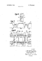
- FIG. 6 is a plan view of a third example of handrail, without a cover fitted
- FIG. 7 is a sectional view on line 7-7 on FIG. 6;
- FIG. 8 is an under plan view of a further example of handrail, without a cover fitted.
- the handrail shown in FIGS. 1 to 4 comprises a body 10 and a cover layer 11, the body being made up of a plurality of discrete lengths of rigid plastics material, each discrete length being moulded on to four spaced apart reinforcing cords 12.
- Each cord 12 comprises a length of steel wire having its ends joined together to form a continuous loop.
- the cords 12 may be made of any flexible material able to withstand tension, for example, terylene, glass fibres, carbon fibres, or other metals in fixed support two spaced apart rigid strips each of strand or strip form.
- Each discrete length of the body 10 is moulded on to the cords 12 by means of an injection moulding process using a rigid thermoplastic material, for example, polypropylene or nylon. During the injection moulding process, the length being moulded is also welded to the next adjacent length which was moulded in. the preceding injection moulding step.
- a rigid thermoplastic material for example, polypropylene or nylon.
- the length being moulded is also welded to the next adjacent length which was moulded in. the preceding injection moulding step.
- Along the underside of the body there is a series of spaced apart recesses 13 disposed along the centre line thereof. Extending outwardly from the recesses 13 towards the edges of the body are ribs 14 each of which is provided with two bosses 15 to strengthen the handrail where the cords 12 connect with the ribs 14.
- flanges 16 and 17 On the underside of the body, there are provided two flanges 16 and 17, spaced from and attached to the body adjacent the recesses 13, which flanges extend outwardly towards the edges of the handrail.
- the flanges l6 and 17 are engageable with guide means which may comprise, for example, two spaced apart angle strips each of which is arranged with one flange extending perpendicularly downwardly from the body portion, the other flange engaging with one of the slots respectively defined by the underface of the body 10 and the flanges 16 and 17.
- Transverse shots 20 are provided at intervals along the upturned edges 18 and 19 (FIG. 3), to permit flexing of the body as it passes around curves, (e.g. around driving or idling pulleys). Additionally, the flanges 16 and 17 are provided with slots 21 at spaced intervals similarly to permit flexing.
- the handrail is completed by a cover layer 11 which is of generally C-shaped section having ribs 22 formed along the inner surface thereof, the ends of the cover layer being turned inwardly at 23.
- the cover layer is pressed over the body, the ribs 22 bearing on the body and the turned inwardly ends 23 engaging the underside of the body 10.
- the cover layer 11 may be made of any flexible plastics or rubber material, for example, a thermoplastics material, (such as polyvinyl chloride,
- the cover may be coloured or otherwisedecorated.
- the cover may be extruded or moulded and made endless by moulding or bonding. It may be made of a very resilient material so that it can be stretched on and hold itself in place without further assistance. Alternatively where necessary it may be bonded on the faces of the body with which it mates.
- the discrete lengths of the moulded body are welded to one another during the injection moulding step by virtue of the heat of the moulding process.
- the discrete lengths may be bonded to each other by means of an adhesive if the material from which the body is moulded does not lend itself to such welding.
- FIG. 5 shows ahandrail similar in general construction to the just-described handrail, but in which only two reinforcing cords are employed.
- the body 26 is shaped so that the neutral axis 27 thereof coincides with the plane of the reinforcing cords 25, and this also conforms to the pitch circle of the toothed driving wheel (not shown) for the handrail,
- flanges 28 and 29 are provided on the underside of the body 26, and are moulded with the body and attached thereto along the longitudinal edges of the body to provide two slots 30 and 31 the mouths of which face one another.
- a guide 32 is arranged to engage the slots when the handrail is in use.
- the cover 33 for the handrail fits around the flanges 28 and 29, as well as over the upper surface of the body 26 as in the previous example.
- FIGS. 6 and 7 show a reinforced body for a handrail, the cover therefor not yet fitted.
- two reinforcing cords 35 and 36 are employed and discrete lengths 37 of rigid thermoplastics material are ejection moulded on to the cords, the lengths being spaced apart from one another.
- the depth of the tooth pockets 38 are increased from the previous described examples to give a greater. bearing area on the driving wheel (not shown).
- FIG. 8 shows a modification of the handrail of FIGS.
- buttresses 39 are moulded on to the ends of the discrete lengths 37 during the injection moulding step to give continuous support for a handrail in an installation in which the guide means and/or supporting means is discontinuous; for example, if the supporting means comprises roller bearings.
- handrails such as shown in FIGS. 6 to 8, in which the moulded lengths 37 are spaced apart, may be used in installations in which the handrail has to move around severe radii.
- the features of the increased tooth pocket depth and the inwardly disposed slots for the guide means may be incorporated in any of the described examples.
- the internal profile of the cover is shaped to suit the body to which it is to be attached.
- a soft cushioning material may be incorporated between the cover and the body.
- the ends of the wires may be joined to form a continuous loop by means of known crimping devices, or by welding, brazing or soldering.
- the join is incorporated into a length of the body portion during an injection moulding step.
- the final length of rigid plastics material to complete an endless loop may be injection moulded in position, as with the other lengths, or may be moulded separate from the handrail and then welded or bonded in position.
- the flanges l6, 17, or 28 29 may be shaped so as to define, with the underside of the body, slots the cross-section of which differ from the rectangular shape shown; for example, the slots may be curved, or part-circular in section.
- a method of making a handrail for passenger conveyors which method comprises injection moulding successively onto a preformed continuous reinforcing member a multiplicity of spaced apart body members of rigid plastics material, the body members being formed with two coplanar flanges extending parallel to and spaced from the underside of the body members along the length of the handrail which define with the body members two opposed slots, which slots are engageable with guide means when the handrail is in use, and then applying to the body members a continuous C-shaped cover of flexible material to provide a continuous handrail.
- the reinforcing member comprises strands, cords or other filamentary material.
- interengaging means are provided on the cover layer and on the body members to attach the cover layer to the body 8 use.
Abstract
A method of making a handrail for an escalator or a passenger conveyor, which includes the steps of forming a body by moulding successive lengths of rigid plastics material onto a continuous reinforcing material, and then applying a continuous cover layer over the body. The cover layer is flexible. The moulded lengths may be spaced apart or abut the next adjacent length. Flanges may be formed on the underside of the body to define opposed slots parallel to the body, and which slots are engageable by guide means to support the handrail when in use.
Description
United States Patent 1191 Cameron et al.
[ Dec. 18, 1973 METHOD OF MAKING HANDRAILS [75] Inventors: James Brisbane Cameron; Bernard Piet Walton-Knight, both of London, England; Otto Floris Bartoo; Joannes Cornelis Molijn, both of Delft, Netherlands [73] Assignee: BTR Industries Limited, London,
England [22] Filed: June 10, 1971 [2]] Appl No.: 151,712
[30] Foreign Application Priority Data Smith l98/l6 R Girardi 264/251 X Primary ExaminerCharlie T. Moon Attorney-Watson, Cole, Grindle & Watson 5 7 ABSTRACT A method of making a handrail for an escalator or a passenger conveyor, which includes the steps of forming a body by moulding successive lengths of rigid plastics material onto a continuous reinforcing material, and then applying a continuous cover layer over the body. The cover layer is flexible. The moulded lengths may be spaced apart or abut the next adjacent length. Flanges may be formed on the underside of the body to define opposed slots parallel to the body, and which slots are engageable by guide means to support the handrail when in use.
[56] References Cited UNITED STATES PATENTS 3,049,213 8/!962 Fabula 198/16 R 7 Claims, 8 Drawing Figures 12 22 12 v \fi i w 'a@ 18 k 11:11; )lY/ui 23 Will/l mmmm 18 1975 3,778,882
SHEET 10F 3 gfigimkaw INVENTOK JAMES BRISBANE CAMERON BERNARD PIET WALTON-KNIGHT OTTO FLORIS BARTOO JOANNES CORNELIS MOLIJ'N WATSON COLE GRINDLE & WATSON ATTORNEYS PATENTEI] [its 18 I975 SHEET 2 OF 3 INVENTORS ATTORNEYS PATENTEnnEc 18 I975 3; 778.882 SHEET 3 BF 3 INVENTORS JAMES BRISBANE CAMERON BERNARD PIET WALTON-KNIGHT OTTO FLORIS BARTOO JOANNES CORNELIS MOLJIN BY B WATSON COLE GRINDLE & WATSON ATTORNEYS 1 METHOD OF MAKING HANDRAILS This invention relates to handrails for escalators, passenger conveyors or the like.
The invention provides a method of making a handrail for escalators, travolators or the like which method comprises moulding successive lengths of rigid plastics material (e.g. nylon, polypropylene or the like) on to a continuous reinforcing material to form a body for the handrail and then applying a continuous cover layer of a flexible material (e.g. polyvinyl chloride, vulcanisable rubbers, sulphonated polyethylenes, polyurethane, polyvinyl chloride nitrile rubber mixtures) to at least the part of the body portion to be gripped in use.
Each length of rigid plastics material may be separated from the next adjacent length.
Alternatively each length of rigid plastics material may adjoin the next adjacent length.
In any of the above methods the reinforcing material may comprise strands or cords or other filamentary material.
The cover layer may be of substantially C-shaped crosssection, there being interengaging means on the cover layer and on the body to attach the cover layer to the body.
The body may be provided with recesses spaced apart along the length of the handrail, which recesses are engageable with toothed driving means.
The body may be provided with two co-planar flanges extending parallel to and spaced from the underside of the body along the length of the handrail which define with the body portion two opposed slots, which slots are engageable with guide means when the handrail is in use.
The flanges may be attached to the body portion at or adjacent the centre thereof and extend towards the longitudinal edges thereof to define two slots in a backto-back relationship.
Alternatively, the flanges may be attached to the body portion at or adjacent the longitudinal edges thereof and extend towards the centre thereof to define two slots the mouths of which face one another.
The body may be formed with transverse slots extending part way through its thickness in a direction normal to the direction of movement of the handrail to permit flexing of the body.
The longitudinal edges of the cover layer may be turned inwardly to provide resilient lips engageable with the sides of the body opposed to the side over which the major portion of the cover layer lies.
The invention also provides a handrail for escalators, passenger conveyors, or the like whenever made by a method according to any of the above described methods.
The invention further provides an escalator, passenger conveyor or the like in which a moving handrail is retained on a fixed support by interengaging guide means which comprises on the handrail two co-planar flanges spaced from and attached to the underside of the handrail, which flanges together with the underside of the handrail define two opposed slots, and on the reference being made to the accompanying drawings in which:
FIG. 1 is a plan view from above a first embodiment of handrail with the cover portion removed;
FIG. 2 is a section on line 2-2 on FIG. 1, with the cover portion included;
FIG. 3 is a section on line 3-3 on FIG. 1, with the cover portion included;
FIG. 4 is a sectional view on line 44 on FIG. 1;
FIG. 5 is a split cross-sectional view taken at two spaced apart locations along the length of a second example of handrail;
FIG. 6 is a plan view of a third example of handrail, without a cover fitted;
FIG. 7 is a sectional view on line 7-7 on FIG. 6; and
FIG. 8 is an under plan view of a further example of handrail, without a cover fitted.
The handrail shown in FIGS. 1 to 4 comprises a body 10 and a cover layer 11, the body being made up of a plurality of discrete lengths of rigid plastics material, each discrete length being moulded on to four spaced apart reinforcing cords 12.
Each cord 12 comprises a length of steel wire having its ends joined together to form a continuous loop. Alternatively, the cords 12 may be made of any flexible material able to withstand tension, for example, terylene, glass fibres, carbon fibres, or other metals in fixed support two spaced apart rigid strips each of strand or strip form.
Each discrete length of the body 10 is moulded on to the cords 12 by means of an injection moulding process using a rigid thermoplastic material, for example, polypropylene or nylon. During the injection moulding process, the length being moulded is also welded to the next adjacent length which was moulded in. the preceding injection moulding step. Along the underside of the body there is a series of spaced apart recesses 13 disposed along the centre line thereof. Extending outwardly from the recesses 13 towards the edges of the body are ribs 14 each of which is provided with two bosses 15 to strengthen the handrail where the cords 12 connect with the ribs 14. On the underside of the body, there are provided two flanges 16 and 17, spaced from and attached to the body adjacent the recesses 13, which flanges extend outwardly towards the edges of the handrail. The flanges l6 and 17 are engageable with guide means which may comprise, for example, two spaced apart angle strips each of which is arranged with one flange extending perpendicularly downwardly from the body portion, the other flange engaging with one of the slots respectively defined by the underface of the body 10 and the flanges 16 and 17.
The edges 18, 19 of the body 10 are turned upwardly as shown in FIG. 2. Transverse shots 20 are provided at intervals along the upturned edges 18 and 19 (FIG. 3), to permit flexing of the body as it passes around curves, (e.g. around driving or idling pulleys). Additionally, the flanges 16 and 17 are provided with slots 21 at spaced intervals similarly to permit flexing.
The handrail is completed by a cover layer 11 which is of generally C-shaped section having ribs 22 formed along the inner surface thereof, the ends of the cover layer being turned inwardly at 23. The cover layer is pressed over the body, the ribs 22 bearing on the body and the turned inwardly ends 23 engaging the underside of the body 10. The cover layer 11 may be made of any flexible plastics or rubber material, for example, a thermoplastics material, (such as polyvinyl chloride,
sulphonated polyethylene), polyurethane, natural vulcanisable rubber, or polyvinyl chloride nitrile rubber mixture. The cover may be coloured or otherwisedecorated. The cover may be extruded or moulded and made endless by moulding or bonding. It may be made of a very resilient material so that it can be stretched on and hold itself in place without further assistance. Alternatively where necessary it may be bonded on the faces of the body with which it mates.
ln'the above described example, the discrete lengths of the moulded body are welded to one another during the injection moulding step by virtue of the heat of the moulding process. Alternatively, the discrete lengths may be bonded to each other by means of an adhesive if the material from which the body is moulded does not lend itself to such welding.
FIG. 5 shows ahandrail similar in general construction to the just-described handrail, but in which only two reinforcing cords are employed. The body 26 is shaped so that the neutral axis 27 thereof coincides with the plane of the reinforcing cords 25, and this also conforms to the pitch circle of the toothed driving wheel (not shown) for the handrail, In this example, flanges 28 and 29 are provided on the underside of the body 26, and are moulded with the body and attached thereto along the longitudinal edges of the body to provide two slots 30 and 31 the mouths of which face one another. A guide 32 is arranged to engage the slots when the handrail is in use. The cover 33 for the handrail fits around the flanges 28 and 29, as well as over the upper surface of the body 26 as in the previous example.
FIGS. 6 and 7 show a reinforced body for a handrail, the cover therefor not yet fitted. In this example, two reinforcing cords 35 and 36 are employed and discrete lengths 37 of rigid thermoplastics material are ejection moulded on to the cords, the lengths being spaced apart from one another. Also, the depth of the tooth pockets 38 are increased from the previous described examples to give a greater. bearing area on the driving wheel (not shown).
FIG. 8 shows a modification of the handrail of FIGS.
6 and 7 in which buttresses 39 are moulded on to the ends of the discrete lengths 37 during the injection moulding step to give continuous support for a handrail in an installation in which the guide means and/or supporting means is discontinuous; for example, if the supporting means comprises roller bearings.
It will be appreciated that handrails such as shown in FIGS. 6 to 8, in which the moulded lengths 37 are spaced apart, may be used in installations in which the handrail has to move around severe radii. Furthermore the features of the increased tooth pocket depth and the inwardly disposed slots for the guide means may be incorporated in any of the described examples.
In any of the above examples the internal profile of the cover is shaped to suit the body to which it is to be attached. A soft cushioning material may be incorporated between the cover and the body.
In examples in which wires are employed to reinforce the handrail, the ends of the wires may be joined to form a continuous loop by means of known crimping devices, or by welding, brazing or soldering. Preferably the join is incorporated into a length of the body portion during an injection moulding step.
The final length of rigid plastics material to complete an endless loop may be injection moulded in position, as with the other lengths, or may be moulded separate from the handrail and then welded or bonded in position.
In all of the above examples, the flanges l6, 17, or 28 29 may be shaped so as to define, with the underside of the body, slots the cross-section of which differ from the rectangular shape shown; for example, the slots may be curved, or part-circular in section.
We claim:
l. A method of making a handrail for passenger conveyors which method comprises injection moulding successively onto a preformed continuous reinforcing member a multiplicity of spaced apart body members of rigid plastics material, the body members being formed with two coplanar flanges extending parallel to and spaced from the underside of the body members along the length of the handrail which define with the body members two opposed slots, which slots are engageable with guide means when the handrail is in use, and then applying to the body members a continuous C-shaped cover of flexible material to provide a continuous handrail.
2. A method as claimed in claim 1, wherein the flanges are attached to the body members adjacent the center thereof andextend toward the longitudinal edges thereof to define two slots in a back-to-back relationship.
3. A method as claimed in claim 1, wherein the flanges are attached to the body members adjacent the longitudinal edges thereof and extend toward the center thereof to define two slots the mouths of which face one another.
4. A method as claimed in claim 1, wherein the body members are formed with transverse slots extending partway through their thickness in a direction normal to the direction of movement of the handrail, to permit I flexing-of the body members.
5. A method as claimed in claim 1, wherein the reinforcing member comprises strands, cords or other filamentary material.
6. A method as claimed in claim 1, wherein interengaging means are provided on the cover layer and on the body members to attach the cover layer to the body 8 use.
Claims (7)
1. A method of making a handrail for passenger conveyors which method comprises injection moulding successively onto a preformed continuous reinforcing member a multiplicity of spaced apart body members of rigid plastics material, the body members being formed with two coplanar flanges extending parallel to and spaced from the underside of the body members along the leNgth of the handrail which define with the body members two opposed slots, which slots are engageable with guide means when the handrail is in use, and then applying to the body members a continuous Cshaped cover of flexible material to provide a continuous handrail.
2. A method as claimed in claim 1, wherein the flanges are attached to the body members adjacent the center thereof and extend toward the longitudinal edges thereof to define two slots in a back-to-back relationship.
3. A method as claimed in claim 1, wherein the flanges are attached to the body members adjacent the longitudinal edges thereof and extend toward the center thereof to define two slots the mouths of which face one another.
4. A method as claimed in claim 1, wherein the body members are formed with transverse slots extending partway through their thickness in a direction normal to the direction of movement of the handrail, to permit flexing of the body members.
5. A method as claimed in claim 1, wherein the reinforcing member comprises strands, cords or other filamentary material.
6. A method as claimed in claim 1, wherein inter-engaging means are provided on the cover layer and on the body members to attach the cover layer to the body members.
7. A method as claimed in claim 1, wherein the body members are formed with recesses spaced apart along the length of the handrail, which recesses are engageable with toothed driving means when the handrail is in use.
Applications Claiming Priority (1)
| Application Number | Priority Date | Filing Date | Title |
|---|---|---|---|
| GB2863470 | 1970-06-12 |
Publications (1)
| Publication Number | Publication Date |
|---|---|
| US3778882A true US3778882A (en) | 1973-12-18 |
Family
ID=10278699
Family Applications (1)
| Application Number | Title | Priority Date | Filing Date |
|---|---|---|---|
| US00151712A Expired - Lifetime US3778882A (en) | 1970-06-12 | 1971-06-10 | Method of making handrails |
Country Status (4)
| Country | Link |
|---|---|
| US (1) | US3778882A (en) |
| DE (1) | DE2129172A1 (en) |
| FR (1) | FR2096219A5 (en) |
| GB (1) | GB1345321A (en) |
Cited By (18)
| Publication number | Priority date | Publication date | Assignee | Title |
|---|---|---|---|---|
| WO1991004219A1 (en) * | 1989-09-12 | 1991-04-04 | Paguag Gmbh & Co. | Handrail for escalators, moving sidewalks and the like and process for its manufacture |
| US5255772A (en) * | 1992-12-22 | 1993-10-26 | Escalator Handrail Company | Handrail for escalators and moving walkways with improved dimensional stability |
| US6086806A (en) * | 1996-04-05 | 2000-07-11 | Ronald H. Ball | Method of splicing thermoplastic articles |
| US6237740B1 (en) | 1998-06-30 | 2001-05-29 | Ronald H. Ball | Composite handrail construction |
| US6673431B1 (en) * | 1998-09-11 | 2004-01-06 | Semperit Aktiengesellschaft Holding | Hand-rail |
| US6761259B1 (en) * | 2003-01-22 | 2004-07-13 | Mitsubishi Denki Kabushiki Kaisha | Moving handrail for passenger conveyor |
| US20050066500A1 (en) * | 2003-09-25 | 2005-03-31 | Christian-Andre Keun | Method and apparatus for continuously joining a handrail for an escalator or moving walkway |
| US20050173224A1 (en) * | 2004-01-16 | 2005-08-11 | Ronald H. Ball | Positive drive handrail assembly |
| WO2006121459A1 (en) * | 2005-05-05 | 2006-11-16 | Otis Elevator Company | Passenger conveyor handrail with sliding material on toothed driven surface |
| WO2007055693A1 (en) * | 2005-11-14 | 2007-05-18 | Otis Elevator Company | Passenger conveyor handrail having a gripping surface with a generally circular cross-section |
| US20080271974A1 (en) * | 2005-04-08 | 2008-11-06 | El-Wardany Tahany I | Passenger Conveyor Handrail and Method of Manufacture |
| US20100237535A1 (en) * | 2007-09-10 | 2010-09-23 | Ehc Canada, Inc. | Method and apparatus for pretreatment of a slider layer for extruded composite handrails |
| US20100258403A1 (en) * | 2007-09-10 | 2010-10-14 | Viqar Haider | Modified handrail |
| US20100283173A1 (en) * | 2007-09-10 | 2010-11-11 | Andrew Oliver Kenny | Method and apparatus for extrusion of thermoplastic handrail |
| US20110083938A1 (en) * | 2008-05-21 | 2011-04-14 | Thomas Illedits | Handrail for an escalator or a moving walkway |
| US9981415B2 (en) | 2007-09-10 | 2018-05-29 | Ehc Canada, Inc. | Method and apparatus for extrusion of thermoplastic handrail |
| US10160623B2 (en) | 2015-05-07 | 2018-12-25 | Ehc Canada, Inc. | Compact composite handrails with enhanced mechanical properties |
| US10350807B2 (en) | 2007-09-10 | 2019-07-16 | Ehc Canada, Inc. | Method and apparatus for extrusion of thermoplastic handrail |
Families Citing this family (2)
| Publication number | Priority date | Publication date | Assignee | Title |
|---|---|---|---|---|
| BE794338A (en) * | 1972-01-24 | 1973-05-16 | Pahl Gummi Asbest | HANDRAIL FOR WALKING STAIRS |
| DE3715679A1 (en) * | 1987-05-15 | 1988-12-01 | Taurus Gumiipari Vallalat | RUNNING TAPE MADE OF ELASTIC MATERIAL, ESPECIALLY FOR RAILING OF ESCALATORS OR. GETTING AROUND |
Citations (3)
| Publication number | Priority date | Publication date | Assignee | Title |
|---|---|---|---|---|
| US3049213A (en) * | 1960-04-22 | 1962-08-14 | Otis Elevator Co | Moving stairway |
| US3415924A (en) * | 1960-08-24 | 1968-12-10 | Girardi Antonio Lawrence | Method of manufacturing extensible conveyor belts |
| US3633725A (en) * | 1969-06-23 | 1972-01-11 | Btr Industries Ltd | Handrails for escalators and travolators |
-
1971
- 1971-05-28 GB GB2863470A patent/GB1345321A/en not_active Expired
- 1971-06-10 US US00151712A patent/US3778882A/en not_active Expired - Lifetime
- 1971-06-11 FR FR7121215A patent/FR2096219A5/fr not_active Expired
- 1971-06-11 DE DE19712129172 patent/DE2129172A1/en active Pending
Patent Citations (3)
| Publication number | Priority date | Publication date | Assignee | Title |
|---|---|---|---|---|
| US3049213A (en) * | 1960-04-22 | 1962-08-14 | Otis Elevator Co | Moving stairway |
| US3415924A (en) * | 1960-08-24 | 1968-12-10 | Girardi Antonio Lawrence | Method of manufacturing extensible conveyor belts |
| US3633725A (en) * | 1969-06-23 | 1972-01-11 | Btr Industries Ltd | Handrails for escalators and travolators |
Cited By (33)
| Publication number | Priority date | Publication date | Assignee | Title |
|---|---|---|---|---|
| US5275270A (en) * | 1989-09-12 | 1994-01-04 | Miklos Dobo | Handrail for escalators, moving walkways and the like and a process for its production |
| WO1991004219A1 (en) * | 1989-09-12 | 1991-04-04 | Paguag Gmbh & Co. | Handrail for escalators, moving sidewalks and the like and process for its manufacture |
| US5255772A (en) * | 1992-12-22 | 1993-10-26 | Escalator Handrail Company | Handrail for escalators and moving walkways with improved dimensional stability |
| US6086806A (en) * | 1996-04-05 | 2000-07-11 | Ronald H. Ball | Method of splicing thermoplastic articles |
| US6237740B1 (en) | 1998-06-30 | 2001-05-29 | Ronald H. Ball | Composite handrail construction |
| US6673431B1 (en) * | 1998-09-11 | 2004-01-06 | Semperit Aktiengesellschaft Holding | Hand-rail |
| US6761259B1 (en) * | 2003-01-22 | 2004-07-13 | Mitsubishi Denki Kabushiki Kaisha | Moving handrail for passenger conveyor |
| US7200915B2 (en) * | 2003-09-25 | 2007-04-10 | New-York Hamburger Gunni-Waaren Compagnie Ag | Method for continuously joining a handrail for an escalator or moving walkway |
| US20050066500A1 (en) * | 2003-09-25 | 2005-03-31 | Christian-Andre Keun | Method and apparatus for continuously joining a handrail for an escalator or moving walkway |
| US20050173224A1 (en) * | 2004-01-16 | 2005-08-11 | Ronald H. Ball | Positive drive handrail assembly |
| US7641038B2 (en) * | 2005-04-08 | 2010-01-05 | Otis Elevator Company | Passenger conveyor handrail and method of manufacture |
| US20080271974A1 (en) * | 2005-04-08 | 2008-11-06 | El-Wardany Tahany I | Passenger Conveyor Handrail and Method of Manufacture |
| WO2006121459A1 (en) * | 2005-05-05 | 2006-11-16 | Otis Elevator Company | Passenger conveyor handrail with sliding material on toothed driven surface |
| AU2005331539B2 (en) * | 2005-05-05 | 2010-12-02 | Otis Elevator Company | Passenger conveyor handrail with sliding material on toothed driven surface |
| US20080190733A1 (en) * | 2005-05-05 | 2008-08-14 | Changsheng Guo | Passenger Conveyor Handrail With Sliding Material on Toothed Driven Surface |
| US7562759B2 (en) | 2005-05-05 | 2009-07-21 | Otis Elevator Company | Passenger conveyor handrail with sliding material on toothed driven surface |
| US7614490B2 (en) | 2005-11-14 | 2009-11-10 | Otis Elevator Company | Passenger conveyor handrail having a gripping surface with a generally circular cross-section |
| WO2007055693A1 (en) * | 2005-11-14 | 2007-05-18 | Otis Elevator Company | Passenger conveyor handrail having a gripping surface with a generally circular cross-section |
| CN101304931B (en) * | 2005-11-14 | 2013-04-10 | 奥蒂斯电梯公司 | Passenger conveying apparatus handrail with approximate circular cross-section grasping surface |
| US20080202890A1 (en) * | 2005-11-14 | 2008-08-28 | Milton-Benoit John M | Passenger Conveyor Handrail Having a Gripping Surface with a Generally Circular Cross-Section |
| US10350807B2 (en) | 2007-09-10 | 2019-07-16 | Ehc Canada, Inc. | Method and apparatus for extrusion of thermoplastic handrail |
| US20100237535A1 (en) * | 2007-09-10 | 2010-09-23 | Ehc Canada, Inc. | Method and apparatus for pretreatment of a slider layer for extruded composite handrails |
| US20100258403A1 (en) * | 2007-09-10 | 2010-10-14 | Viqar Haider | Modified handrail |
| US20100283173A1 (en) * | 2007-09-10 | 2010-11-11 | Andrew Oliver Kenny | Method and apparatus for extrusion of thermoplastic handrail |
| US10940625B2 (en) | 2007-09-10 | 2021-03-09 | Ehc Canada, Inc. | Method and apparatus for extrusion of thermoplastic handrail |
| US8323544B2 (en) | 2007-09-10 | 2012-12-04 | Ehc Canada, Inc. | Method and apparatus for pretreatment of a slider layer for extruded composite handrails |
| US8820511B2 (en) | 2007-09-10 | 2014-09-02 | Ehc Canada, Inc. | Modified handrail |
| US9579839B2 (en) | 2007-09-10 | 2017-02-28 | Ehc Canada, Inc. | Apparatus for extrusion of thermoplastic handrail |
| US9981415B2 (en) | 2007-09-10 | 2018-05-29 | Ehc Canada, Inc. | Method and apparatus for extrusion of thermoplastic handrail |
| US8800744B2 (en) * | 2008-05-21 | 2014-08-12 | Inventio Ag | Handrail for an escalator or a moving walkway |
| US20110083938A1 (en) * | 2008-05-21 | 2011-04-14 | Thomas Illedits | Handrail for an escalator or a moving walkway |
| US10287133B2 (en) | 2015-05-07 | 2019-05-14 | Ehc Canada, Inc. | Compact composite handrails with enhanced mechanical properties |
| US10160623B2 (en) | 2015-05-07 | 2018-12-25 | Ehc Canada, Inc. | Compact composite handrails with enhanced mechanical properties |
Also Published As
| Publication number | Publication date |
|---|---|
| GB1345321A (en) | 1974-01-30 |
| DE2129172A1 (en) | 1972-02-03 |
| FR2096219A5 (en) | 1972-02-11 |
Similar Documents
| Publication | Publication Date | Title |
|---|---|---|
| US3778882A (en) | Method of making handrails | |
| US3633725A (en) | Handrails for escalators and travolators | |
| US3865225A (en) | Handrail for escalator | |
| US5275270A (en) | Handrail for escalators, moving walkways and the like and a process for its production | |
| US20080051240A1 (en) | Flat Belt for Elevator Systems, Comprising Reinforcements | |
| AU585553B2 (en) | Conveyor belt for bulk material handling | |
| CN102006988A (en) | Process and device for producing a belt-like carrier means for an elevator system, belt-like carrier means and elevator system comprising such a carrier means | |
| JP2008044793A (en) | Elevator belt for elevator device and method of manufacturing the elevator belt | |
| CA2564182C (en) | Transporting device with transporting belt | |
| GB1430176A (en) | Cover band conveyor | |
| US3666085A (en) | Mechanical belting | |
| CN101121488A (en) | Lift system, load-bearing mechanism for such a lift system and method for assembly of such a load-bearing mechanism | |
| EP1625087B1 (en) | Non-slip conveyor and method for producing same | |
| USRE27439E (en) | Inclined moving walkway arrangement | |
| CN101128372A (en) | Conveyer belt with guide | |
| US3181690A (en) | Segmental conveyor belt | |
| US3052133A (en) | Drive for moving stairways | |
| US7241354B2 (en) | Non-slip conveyor and method for producing same | |
| CN214526146U (en) | High-elongation conveying belt capable of realizing small-radius turning | |
| JP2834683B2 (en) | Connection structure of belt with belt | |
| JPH08259164A (en) | Handrail and its production | |
| GB1195948A (en) | Method of Producing a Conveyor Belt having a Layer of Foam Plastics. | |
| JPH0617771Y2 (en) | Guide body for meandering prevention conveyor belt | |
| EP0056035A1 (en) | Improvements in or relating to conveyor belts | |
| EP0221683A2 (en) | Device for the transport of cross seated cigarettes |