US3824540A - Bicycle lock and alarm apparatus - Google Patents
Bicycle lock and alarm apparatus Download PDFInfo
- Publication number
- US3824540A US3824540A US27580272A US3824540A US 3824540 A US3824540 A US 3824540A US 27580272 A US27580272 A US 27580272A US 3824540 A US3824540 A US 3824540A
- Authority
- US
- United States
- Prior art keywords
- alarm
- case
- lock
- bolt
- bicycle
- Prior art date
- Legal status (The legal status is an assumption and is not a legal conclusion. Google has not performed a legal analysis and makes no representation as to the accuracy of the status listed.)
- Expired - Lifetime
Links
Images


Classifications
-
- E—FIXED CONSTRUCTIONS
- E05—LOCKS; KEYS; WINDOW OR DOOR FITTINGS; SAFES
- E05B—LOCKS; ACCESSORIES THEREFOR; HANDCUFFS
- E05B45/00—Alarm locks
- E05B45/005—Chain-locks, cable-locks or padlocks with alarms
-
- B—PERFORMING OPERATIONS; TRANSPORTING
- B62—LAND VEHICLES FOR TRAVELLING OTHERWISE THAN ON RAILS
- B62H—CYCLE STANDS; SUPPORTS OR HOLDERS FOR PARKING OR STORING CYCLES; APPLIANCES PREVENTING OR INDICATING UNAUTHORIZED USE OR THEFT OF CYCLES; LOCKS INTEGRAL WITH CYCLES; DEVICES FOR LEARNING TO RIDE CYCLES
- B62H5/00—Appliances preventing or indicating unauthorised use or theft of cycles; Locks integral with cycles
- B62H5/003—Appliances preventing or indicating unauthorised use or theft of cycles; Locks integral with cycles using chains or cables
-
- B—PERFORMING OPERATIONS; TRANSPORTING
- B62—LAND VEHICLES FOR TRAVELLING OTHERWISE THAN ON RAILS
- B62H—CYCLE STANDS; SUPPORTS OR HOLDERS FOR PARKING OR STORING CYCLES; APPLIANCES PREVENTING OR INDICATING UNAUTHORIZED USE OR THEFT OF CYCLES; LOCKS INTEGRAL WITH CYCLES; DEVICES FOR LEARNING TO RIDE CYCLES
- B62H5/00—Appliances preventing or indicating unauthorised use or theft of cycles; Locks integral with cycles
- B62H5/20—Appliances preventing or indicating unauthorised use or theft of cycles; Locks integral with cycles indicating unauthorised use, e.g. acting on signalling devices
-
- Y—GENERAL TAGGING OF NEW TECHNOLOGICAL DEVELOPMENTS; GENERAL TAGGING OF CROSS-SECTIONAL TECHNOLOGIES SPANNING OVER SEVERAL SECTIONS OF THE IPC; TECHNICAL SUBJECTS COVERED BY FORMER USPC CROSS-REFERENCE ART COLLECTIONS [XRACs] AND DIGESTS
- Y10—TECHNICAL SUBJECTS COVERED BY FORMER USPC
- Y10T—TECHNICAL SUBJECTS COVERED BY FORMER US CLASSIFICATION
- Y10T70/00—Locks
- Y10T70/50—Special application
- Y10T70/5872—For cycles
Definitions
- An electrical UNITED STATES PATENTS circuit including an electrical conductor running 481,236 8/1892 Macauley 70/226 thmugh the length of the cable and responsive to in- 597,891 1/1898 walstmm et 70/234 terruption of the conductor for activating an alarm.
- the present invention is directed to a locking and alarm device and more particularly a device to be used in conjunction with immobilizing the wheels of a bicycle and providing an alarm indication if the lock is removed other than in the normal fashion.
- the invention described herein is a bicycle lock and alarm apparatus which has a cable of sufficient length to extend through the wheels and the framework of a bicycle upon which it is adapted to be installed. There are locking means afforded to join the ends of the cable to form a continuous loop.
- the cable contains-a continuous conductor which is an integral part of a circuit which also includes a buzzer alarm. The conductor is positioned in the circuit in such a manner as to actuate the buzzer alarm in theevent the conductor is cut. Cables are replaceable in the lock assembly.
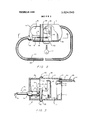
- FIG. 1 is an exploded view showing the installation of the apparatus on the bicycle frame.
- FIG. 2 is a plan view of the cable and the locking device in the preferred embodiment.
- FIG. 3 is a sectional elevation showing the assembly of the'parts and the configuration of the bolt and the latch.
- FIG. 4 is a schematic circuit diagram showing the circuit contained in the preferred embodiment.
- FIG. 5 is a schematic circuit diagram showing a modification of the circuit contained in the preferred embodiment.
- FIG. 1 there is shown an exploded view of the bicycle lock and alarm apparatus assembly 10 as well as the manner in which it is attached to a bicycle framework 12.
- a receptacle means 11 joins the ends of a cable as hereinafter described and in this embodiment includes a bolt receiving member 13, a mounting plate 14, and a lock-alarm case 15.
- the bolt receiving member 13 which may be molded of some durable impact resistant plastic, has a clearance space 16 extending therethrough for receiving a portion of the framework 12.
- the clearance 16 is adapted to fit around thact portion of the framework 12 immediately below and supporting a bicycle seat 17.
- Bolt guide 18 extends through the member 13 in a direction at right angles to the clearance space 16 and to one side thereof.
- the bolt guide 18 has a slot 19 in one wall extending in a direction par-' allel to the axis of the guide 18.
- the bolt receiving member 13 also has a pattern of holes 20 adapted to receive screws 23.
- the mounting plate 14 has a pattern of holes 25 which match the pattern of holes 20 in the bolt receiving member 13.
- the screws 23 are inserted through the holes 25 in the mounting plate 14 to engage the threads of holes 20 to affix the member 13 and plate 14 to the bicycle frame 12.
- the mounting plate 14 may have a hole 26 inline with the bolt guide 18 and of substantially the same diameter as the inside of the bolt guide 18.
- the plate has a narrow slot 29 running in a vertical direction through the mounting plate 14 on a center line of the hole 26.
- the plate 14 may be a metal plate with its top and bottom edges bent through approximately to form case guides 30 opposite the side mounting the bolt receiving member 13.
- the lock-alarm case or box 15 which may also be formed of some durable impact resistant plastic mate rial has an open face 32 with flanges 33 located at the top and bottom of the open face 32.
- the case 15 has a plurality of holes 35 in communication with the inside of the case 15. Holes 35 are present to pass audible sound across the wall of case 15. In the event the case is fabricated of a substance capable of transmitting audible sound directly therethrough the holes become unnecessary.
- the flanges 33 are adapted to be inserted into the case guides 30 on the mounting plate 14 when the lock alarm case 15 is in the locked position.
- the lock alarm case 15 includes mounting means 36 for mounting an alarm 37, such as a buzzer adjacent to the holes 35.
- Battery mounting means 38 is located inside the case 15 and may be of a material such as plastic. In this embodiment the battery mounting means 38 carries proper terminals and connections 41 to place four 1.5 volt pen-light batteries 42 in series thus providing a 6 volt source voltage.
- Electrical circuitry as seen in FIG. 4 provides a normally off relay function between the batteries 42 and the alarm 37.
- the 6 volt terminal of the batteries 42 is connected to one-side of the alarm 37.
- the other side of alarm 37 is connected to the emitter of a PNP transistor 01.
- R2 represents a biasing resistor between the from ground.
- a cable 43 which may have a plastic jacket 44 is secured to the inside of case by a grommet 47.
- a continuous conductor 48 runs through the length of the cable 43 inside the jacket 44 and provides a connection between the emitter and the base'of transistor Q2 as seen in FIG. 4, thus placing the base at ground potential.
- the internal configuration of case 15 is such as to provide mounting means 49 for the various circuit Components.
- the lock-alarm'case 15 is adapted to mount locking means 50 extending through one wall of the case 15.
- locking means 50 is shown as a key operated tumbler type lock, but it is also anticipated that aconforming type of combinationlock might be used.
- An appropriate lock release such as key 53 is utilized to cause rotation of revolving plug 54.
- latch 55 mounted on revolving plug 54 is latch 55 which is of a thickness such as to pass freely through the bolt guide slot 19 and the slot 29 in mounting plate 14. Latch 55 is yieldably urged to a latched position by spring 57.
- Bolt 56 Mounted on the end of cable 43 is bolt 56 of a size and shape adapted to fit into bolt guide 18.
- Bolt 56 has a bolt notch 59 near its free end adapted to receive latch 55.
- Continuous conductor 48 extends well into the interior of bolt 56, when it is mounted on the end of cable 43.
- switch S1 represents an interruption in the continuous conductor 48 which holds the base of Q2 at ground potential. Such a switch opening occurs when cable 43 is cut.
- the base of O2 is normally biased to an off condition by maintaining it at the same potential as the emitter.
- the base of O2 is unclamped from the emitter potential by opening 81, or cutting cable 43, it is immediately placed above the emitter potential by virtue of a circuit extending from the positive voltage through the buzzer alarm 37, and through R1 to the base ofQZ. 02, being an NPN transistor, conducts when the base is placed in a positive condition with respect to the emitter and a forward voltage is placed between collector and emitter.
- the circuit begins to draw current from the battery source 42 through buzzer alarm 37 and resistor R2 to ground.
- the buzzer 37 thus begins to produce an audible alarm.
- the drop of voltage through R2 due to conduction through Q2 places the base of Q1 at a potential lower than the emitter of Q1.
- 01 being a PNP device conducts when the base voltage is lower than the emitter voltage and a forward voltage is placed between emitter and collector. This places a higher potential at the base of transistor Q2 causing O2 to fully conduct.
- the alarm continues to emit its abrasive sound as long as power is applied when conductor 48 is cut, which is represented by placing S1 in FIG. 4 in an open condition. It can be seen that if S] is closed the audible alarm will cease. In this embodiment if S1 remains open the circuit draws approximately a 1 amp transient initially, reducing to 300 to 400 milliamps steady state, which is sustainable by the batteries42 for up to a 1 hour period.
- the circuit shown in FIG. 4 thus acts as a relay which is normally held in the off position, and
- the installation of the lock-alarm device described above can be seen to immobilize the bicycle wheels providing a mechanical lock preventing operation of the bicycle; It is also anticipated that the cable 43 will be utilized to enclose some firmly implanted or bulky object to prevent the bicycle from being removed in an inoperative condition. Under these circumstances the determined bicycle thief is quite likely to attempt to cut cable 43 to facilitate removal of the bicycle from the the reliability of the lock-alarm feature.
- the lock and alarm apparatus assembly described herein provides both a physical and psychological deterrent for potential bicycle thieves. lts sturdy construction practically precludes destruction on the bicycle. in the event the physical locking cable is cut it is likely the potential thief will be induced by the alarm to flee without the intended object of his larceny.
- FIG. 5 Another embodiment of the invention disclosed herein includes an additional feature which is shown in FIG. 5.
- This embodiment contains all of the features mentioned heretofore and has an additional characteristic designed to discourage the more sophisticated bicycle thief.
- a person determined to steal a bicycle with the disclosed type of lock installed and having some knowledge of the circuitry contained, may attempt to make contact with the continuous conductor 48 contained in the cable 44 and create a path parallel to the conductor 48 outside of the bicycle frame and wheels.
Abstract
A bicycle lock and alarm apparatus for use as a preventive or deterrent device in controlling bicycle thievery. A continuous cable adapted to extend through the bicycle wheels and also about the bicycle frame to immobilize the wheels and locking means to join the ends of the cable to form a loop. An electrical circuit including an electrical conductor running through the length of the cable and responsive to interruption of the conductor for activating an alarm.
Description
United States Patent [191 i [1 1 3,824,540 Smith, II July 16, 1974 [54] BICYCLE LOCK AND ALARM APPARATUS 2,988,708 6/1961 Schmidt 340/256 8 l 9 P 3 7 1 2,2222, :92; Kate, 6, a, 2412,22 one Flrst L, L08 Altos, callf- 3,781,861 12/1973 Adler, Jr. et a1 340/280 94022 [22] Filed: July 27, 1972 Primary Examiner lohn W. Caldwell Assistant Examiner-Joseph E. Nowicki [21] Appl 275802 Attorney, Agent, or FirmFlehr, Hohbach, Test, A1-
britton & Herbert [52] US. Cl 340/63, 70/233, 116/33,
180/] 14, 340/256, 340/280 57 ABSTRACT [51] lnt.Cl B60r 25/10,G80b 21/00 l l k, d l I t f v I [58] Field of Search 340/63, 256, 280, 283, F e 3 f 'f' 340/274; /225 226 227 234 17, 233; ven we or e erren evrce in con r0 mg icyc e 307/10 AT /1 1 16/33 62 81 thievery. A continuous cable adapted to extend through the bicycle wheels and also about the bicycle frame to immobilize the wheels and locking means to [56] References Cited join the ends of the cable to form a loop. An electrical UNITED STATES PATENTS circuit including an electrical conductor running 481,236 8/1892 Macauley 70/226 thmugh the length of the cable and responsive to in- 597,891 1/1898 walstmm et 70/234 terruption of the conductor for activating an alarm. 736,409 8/1903 Kuhn 116/33 1,747,194 2/1930 Thomas 340/280 2 Claims,5Drawing Figures II l2 5- 33 'll/I111 f PAIENTED Jul 5 i974 BACKGROUND OF THE INVENTION The present invention is directed to a locking and alarm device and more particularly a device to be used in conjunction with immobilizing the wheels of a bicycle and providing an alarm indication if the lock is removed other than in the normal fashion.
Bicycle sales have recently risen to unexpected heights and for the first time appear to be well on their way to exceeding in number the sale of new automobiles. Accompanying the burgeoning popularity of the bicycle is a burden placed on the law enforcement agencies in populous areas in the form of prevention and investigation of bicycle theft. Some law enforcement agencies have estimated that up to four percent of the total number of bicycles in a given area will be subject to theft this year. I
In many instances of bicycle theft the bicycles have been properly locked when left unattended by their owners. The locks have been cut and the bicycles ridden or carried away. In many instances of this type an audible alarm would have alerted the owner nearby, or others in the immediate area, ofthe impending theft. In many instances the alarm would have immediately frightened the potential thief from the scene, admittedly leaving behind a lock with a cut cable, but also the bicycle.
OBJECTS AND SUMMARY OF TI-IE INVENTION It is a general object of the invention to provide a deterrent to bicycle theft.
It is another object of the invention to provide a sturdy locking device constituting a mechanical bar to bicycle theft.
It is another'object of the invention to provide a loud audible alarm as a warning of tampering with the locking device as might occur during an attempt to steal the bicycle.
It is another object of the invention to apprise potential bicycle thieves of the difficulties involved in spiriting away a protected bicycle.
The invention described herein is a bicycle lock and alarm apparatus which has a cable of sufficient length to extend through the wheels and the framework of a bicycle upon which it is adapted to be installed. There are locking means afforded to join the ends of the cable to form a continuous loop. The cable contains-a continuous conductor which is an integral part of a circuit which also includes a buzzer alarm. The conductor is positioned in the circuit in such a manner as to actuate the buzzer alarm in theevent the conductor is cut. Cables are replaceable in the lock assembly.
BRIEF DESCRIPTION OF THE DRAWINGS FIG. 1 is an exploded view showing the installation of the apparatus on the bicycle frame.
FIG. 2 is a plan view of the cable and the locking device in the preferred embodiment.
FIG. 3 is a sectional elevation showing the assembly of the'parts and the configuration of the bolt and the latch.
FIG. 4 is a schematic circuit diagram showing the circuit contained in the preferred embodiment.
FIG. 5 is a schematic circuit diagram showing a modification of the circuit contained in the preferred embodiment.
DETAILED DESCRIPTION OF THE PREFERRED EMBODIMENT Referring to FIG. 1 there is shown an exploded view of the bicycle lock and alarm apparatus assembly 10 as well as the manner in which it is attached to a bicycle framework 12. A receptacle means 11 joins the ends of a cable as hereinafter described and in this embodiment includes a bolt receiving member 13, a mounting plate 14, and a lock-alarm case 15.
The bolt receiving member 13 which may be molded of some durable impact resistant plastic, has a clearance space 16 extending therethrough for receiving a portion of the framework 12. In this embodiment the clearance 16 is adapted to fit around thact portion of the framework 12 immediately below and supporting a bicycle seat 17. Bolt guide 18 extends through the member 13 in a direction at right angles to the clearance space 16 and to one side thereof. The bolt guide 18 has a slot 19 in one wall extending in a direction par-' allel to the axis of the guide 18. The bolt receiving member 13 also has a pattern of holes 20 adapted to receive screws 23.
The mounting plate 14 has a pattern of holes 25 which match the pattern of holes 20 in the bolt receiving member 13. The screws 23 are inserted through the holes 25 in the mounting plate 14 to engage the threads of holes 20 to affix the member 13 and plate 14 to the bicycle frame 12. The mounting plate 14 may have a hole 26 inline with the bolt guide 18 and of substantially the same diameter as the inside of the bolt guide 18. The plate has a narrow slot 29 running in a vertical direction through the mounting plate 14 on a center line of the hole 26. The plate 14 may be a metal plate with its top and bottom edges bent through approximately to form case guides 30 opposite the side mounting the bolt receiving member 13.
The lock-alarm case or box 15 which may also be formed of some durable impact resistant plastic mate rial has an open face 32 with flanges 33 located at the top and bottom of the open face 32. The case 15 has a plurality of holes 35 in communication with the inside of the case 15. Holes 35 are present to pass audible sound across the wall of case 15. In the event the case is fabricated of a substance capable of transmitting audible sound directly therethrough the holes become unnecessary. The flanges 33 are adapted to be inserted into the case guides 30 on the mounting plate 14 when the lock alarm case 15 is in the locked position.
Referring to FIGS. 2 and 3 it may be seen that the lock alarm case 15 includes mounting means 36 for mounting an alarm 37, such as a buzzer adjacent to the holes 35. Battery mounting means 38 is located inside the case 15 and may be of a material such as plastic. In this embodiment the battery mounting means 38 carries proper terminals and connections 41 to place four 1.5 volt pen-light batteries 42 in series thus providing a 6 volt source voltage.
Electrical circuitry as seen in FIG. 4 provides a normally off relay function between the batteries 42 and the alarm 37. The 6 volt terminal of the batteries 42 is connected to one-side of the alarm 37. The other side of alarm 37 is connected to the emitter of a PNP transistor 01. R2 represents a biasing resistor between the from ground.
tween the emitter of Q1 and the base of Q2, serving as a bias resistor for Q2 when the base of O2 is unclamped A cable 43 which may have a plastic jacket 44 is secured to the inside of case by a grommet 47. A continuous conductor 48 runs through the length of the cable 43 inside the jacket 44 and provides a connection between the emitter and the base'of transistor Q2 as seen in FIG. 4, thus placing the base at ground potential. The internal configuration of case 15 is such as to provide mounting means 49 for the various circuit Components.
The lock-alarm'case 15 is adapted to mount locking means 50 extending through one wall of the case 15. In this embodiment locking means 50 is shown as a key operated tumbler type lock, but it is also anticipated that aconforming type of combinationlock might be used. An appropriate lock release such as key 53 is utilized to cause rotation of revolving plug 54. Mounted on revolving plug 54 is latch 55 which is of a thickness such as to pass freely through the bolt guide slot 19 and the slot 29 in mounting plate 14. Latch 55 is yieldably urged to a latched position by spring 57.
Mounted on the end of cable 43 is bolt 56 of a size and shape adapted to fit into bolt guide 18. Bolt 56 has a bolt notch 59 near its free end adapted to receive latch 55. Continuous conductor 48 extends well into the interior of bolt 56, when it is mounted on the end of cable 43.
Turning now to the operation of the bicycle lockalarm it can be seen from FIG. 2 that bolt receiving memberl3 and mounting plate 14 are fixedly mounted tothe framework 12 by installing screws 23. The lock alarm case 15 containing one end of cable 43, locking means 50 and latch 55, buzzer alarm 37, and the electrical circuit and connections as shown in. FIG. 4, is then installed on the locking plate 14 in the following manner. Top and bottom flanges 33 of lock alarm case- 15 are aligned with the top and bottom case guides 30 on mounting plate 14. Key 53'is inserted into locking means 50 and rotated to cause latch 55 to clear mountscene. In such an event an abrasive audible alarm emits from the lock-alarm case 15 in the following manner. Referring now to FIG. 4, switch S1 represents an interruption in the continuous conductor 48 which holds the base of Q2 at ground potential. Such a switch opening occurs when cable 43 is cut. The base of O2 is normally biased to an off condition by maintaining it at the same potential as the emitter. When the base of O2 is unclamped from the emitter potential by opening 81, or cutting cable 43, it is immediately placed above the emitter potential by virtue of a circuit extending from the positive voltage through the buzzer alarm 37, and through R1 to the base ofQZ. 02, being an NPN transistor, conducts when the base is placed in a positive condition with respect to the emitter and a forward voltage is placed between collector and emitter. Thus the circuit begins to draw current from the battery source 42 through buzzer alarm 37 and resistor R2 to ground. The buzzer 37 thus begins to produce an audible alarm. The drop of voltage through R2 due to conduction through Q2 places the base of Q1 at a potential lower than the emitter of Q1. 01 being a PNP device conducts when the base voltage is lower than the emitter voltage and a forward voltage is placed between emitter and collector. This places a higher potential at the base of transistor Q2 causing O2 to fully conduct. There is some voltage drop in the circuit from the emitter of Q1 to ground and therefor buzzer alarm 37 must be capable of fully operating at less than the positive terminal voltage V. In this embodiment the alarm 37 is capable of full operation at 3 volts.
The alarm continues to emit its abrasive sound as long as power is applied when conductor 48 is cut, which is represented by placing S1 in FIG. 4 in an open condition. It can be seen that if S] is closed the audible alarm will cease. In this embodiment if S1 remains open the circuit draws approximately a 1 amp transient initially, reducing to 300 to 400 milliamps steady state, which is sustainable by the batteries42 for up to a 1 hour period. The circuit shown in FIG. 4 thus acts as a relay which is normally held in the off position, and
ing plate 14 as case 15 is slidinto case guides 30 such I v the end of cable 43 is then inserted into bolt guide 18 whereupon latch is displacedupward by the leading end of bolt 56 until bolt notch 59 lies beneath latch 55, whereupon latch 55 is brought into engagement with bolt 56 at notch 59 by spring 57.
The installation of the lock-alarm device described above can be seen to immobilize the bicycle wheels providing a mechanical lock preventing operation of the bicycle; It is also anticipated that the cable 43 will be utilized to enclose some firmly implanted or bulky object to prevent the bicycle from being removed in an inoperative condition. Under these circumstances the determined bicycle thief is quite likely to attempt to cut cable 43 to facilitate removal of the bicycle from the the reliability of the lock-alarm feature. Thus it is seen that the lock and alarm apparatus assembly described herein provides both a physical and psychological deterrent for potential bicycle thieves. lts sturdy construction practically precludes destruction on the bicycle. in the event the physical locking cable is cut it is likely the potential thief will be induced by the alarm to flee without the intended object of his larceny.
Another embodiment of the invention disclosed herein includes an additional feature which is shown in FIG. 5. This embodiment contains all of the features mentioned heretofore and has an additional characteristic designed to discourage the more sophisticated bicycle thief. A person determined to steal a bicycle with the disclosed type of lock installed and having some knowledge of the circuitry contained, may attempt to make contact with the continuous conductor 48 contained in the cable 44 and create a path parallel to the conductor 48 outside of the bicycle frame and wheels.
Claims (2)
1. A bicycle lock and alarm apparatus adapted to mount on the framework of a bicycle to immobilize the wheels and provide an alarm in the event the lock is forced comprising a lock-alarm case capable of passing sound through its walls, a bolt receiving member having a bolt guide, means to join said bolt receiving member together with said lock-alarm case, an electrical circuit mounted in said lock-alarm case, a buzzer-alarm connected to said circuit mounted within said case, an electrical energy source connected to said circuit mounted within said case, locking means mounted in said case, a latch attached to said locking means, a cable secured at one end within said case, a continuous conductor initiating and terminating within said lock alarm case extending throughout the length of said cable connected to said circuit, and a bolt secured to the free end of said cable formed to be engaged by said latch when inserted into said bolt guide, said circuit operating to activate said alarm when said conductor is interrupted.
2. In a bicycle lock and alarm apparatus for mounting on a bicycle having a framework, a bolt receiving member adapted to mount on a portion of the framework, a bolt guide having walls extending through the bolt receiving member and having a slot in one wall extending lengthwise of the guide, a mounting face on the bolt receiving member having a pattern of holes to accept fasteners, a mounting plate having a bolt hole of substantially the same dimension as the inside of the bolt guide and aligned with the guide and having a slot extending in a direction between the top and bottom of the plate aligned with the center line of the bolt hole and having a hole pattern for passing fasteners matching the pattern on the face of the bolt receiving member for attaching the plate to the bolt receiving member in a manner surrounding the framework and fixed thereto, top and bottom case guides substantially parallel to each other and formed along the top and bottom of the mounting plate, a lock-alarm case having a mounting face on one side and a plurality of holes on another side, flanges at the top and bottom of the mounting face on the lock-alarm case formed to mate with the top and bottom case guides, a buzzer-alarm mounted on the interior of the lock-alarm case next to the plurality of holes to allow audible noise to pass to the exterior of the case, locking means mounted to rotate in the lock-alarm case, a spring loaded latch attached to the locking means so as to extend through the mounting plate slot when the flanges on the case are fully engaged by the gUides on the mounting plate, a cable secured at one end to the interior of the lock-alarm case of sufficient length to pass through the framework and both wheels of the bicycle, an electrical circuit connected to the buzzer-alarm, a continuous electrical conductor connected to the electrical circuit and extending through the length of the cable, a source of electrical power connected to the circuit, and a bolt secured to the free end of the cable and adapted to fit in the bolt guide, the electrical circuit operating to activate the buzzer-alarm when the continuous electrical conductor is interrupted.
Priority Applications (2)
| Application Number | Priority Date | Filing Date | Title |
|---|---|---|---|
| US27580272 US3824540A (en) | 1972-07-27 | 1972-07-27 | Bicycle lock and alarm apparatus |
| GB3562873A GB1369399A (en) | 1972-07-27 | 1973-07-26 | Bicycle lock and alarm apparatus |
Applications Claiming Priority (1)
| Application Number | Priority Date | Filing Date | Title |
|---|---|---|---|
| US27580272 US3824540A (en) | 1972-07-27 | 1972-07-27 | Bicycle lock and alarm apparatus |
Publications (1)
| Publication Number | Publication Date |
|---|---|
| US3824540A true US3824540A (en) | 1974-07-16 |
Family
ID=23053860
Family Applications (1)
| Application Number | Title | Priority Date | Filing Date |
|---|---|---|---|
| US27580272 Expired - Lifetime US3824540A (en) | 1972-07-27 | 1972-07-27 | Bicycle lock and alarm apparatus |
Country Status (2)
| Country | Link |
|---|---|
| US (1) | US3824540A (en) |
| GB (1) | GB1369399A (en) |
Cited By (56)
| Publication number | Priority date | Publication date | Assignee | Title |
|---|---|---|---|---|
| US3914756A (en) * | 1974-03-11 | 1975-10-21 | Raymond Lee Organization Inc | Portable alarm actuated by attempted theft |
| US3993987A (en) * | 1975-03-03 | 1976-11-23 | Stevens Edward C | Locking device having an integral alarm system |
| US4028916A (en) * | 1976-04-13 | 1977-06-14 | Pender David R | Lock for bicycles and the like |
| US4057986A (en) * | 1976-07-19 | 1977-11-15 | Sarah Zolke | Self-contained alarm lock |
| US4112720A (en) * | 1976-12-01 | 1978-09-12 | Green Leonard O | Bicycle lock assembly |
| US4151506A (en) * | 1976-09-20 | 1979-04-24 | Wilhelm Schoenmetz | Lock and alarm apparatus |
| US4340007A (en) * | 1980-04-18 | 1982-07-20 | Paul Hogan | Portable locking and alarm system |
| US4379281A (en) * | 1981-09-18 | 1983-04-05 | Thomas John C | Alarm system for bicycles and the like |
| US4525702A (en) * | 1981-10-09 | 1985-06-25 | Tadao Kitagawa | Flexible tying member for theftproof device |
| US4535322A (en) * | 1983-08-01 | 1985-08-13 | Yeski Frederick R | Ski theft alarm and runaway ski locator |
| US4546345A (en) * | 1981-08-13 | 1985-10-08 | Honda Giken Kogyo Kabushiki Kaisha | Theft preventing device |
| US4556872A (en) * | 1983-08-18 | 1985-12-03 | John F. Masoncup | Padlock with tamper alarm |
| US4663611A (en) * | 1982-10-15 | 1987-05-05 | Humphrey Chris W | Alarm lock |
| FR2610277A1 (en) * | 1987-01-30 | 1988-08-05 | Agl | Anti-theft device for a two-wheeled vehicle |
| US4776188A (en) * | 1986-12-23 | 1988-10-11 | O. Gene Dalaba | Locking and alarm combination security device |
| US4811578A (en) * | 1983-08-18 | 1989-03-14 | John F. Masoncup | Padlock with tamper-actuated audible and/or inaudible alarm |
| US4866422A (en) * | 1987-05-14 | 1989-09-12 | Psc Limited | Security alarm system |
| GB2221330A (en) * | 1988-07-27 | 1990-01-31 | David Hoffmann | Anti-theft alarm device |
| US4992789A (en) * | 1989-10-31 | 1991-02-12 | Daniel Czerwinski | Marine lock and alarm apparatus |
| US5032823A (en) * | 1988-05-27 | 1991-07-16 | Digital Products Corporation | Secure personnel monitoring system |
| US5200735A (en) * | 1989-07-11 | 1993-04-06 | Hines Thomas N | Weather protected portable security system for in-field use |
| US5291765A (en) * | 1992-12-16 | 1994-03-08 | Gary Hoisington | Bicycle lock bracket |
| WO1994008113A1 (en) * | 1992-10-01 | 1994-04-14 | Merz Metall- Und Kunststoffverarbeitungs Gmbh | Alarm lock |
| US5408213A (en) * | 1993-05-12 | 1995-04-18 | Ungarsohn; Benjamin I. | Portable breakaway alarm system |
| US5408212A (en) * | 1992-09-18 | 1995-04-18 | Brio Corporation | Multi-mode combination alarm and locking apparatus for bicycles, motorcycles and the like |
| US5718134A (en) * | 1996-12-13 | 1998-02-17 | Chang; Chin-Shu | Bicycle cable lock |
| US5727405A (en) * | 1997-02-03 | 1998-03-17 | Cromwell; Daryl | Alarm padlock |
| US5836002A (en) * | 1995-06-01 | 1998-11-10 | Morstein; Jason | Anti-theft device |
| US6060982A (en) * | 1998-04-27 | 2000-05-09 | Holtrop; Perryn H. J. | Bicycle anti-theft alarm system |
| US6199416B1 (en) * | 2000-04-28 | 2001-03-13 | Bee Shen Enterprise Co., Ltd. | Motorcycle lock |
| US6347872B1 (en) * | 2001-02-20 | 2002-02-19 | Delbar Products Inc. | Snap-in rearview mirror assembly for vehicles |
| US6373382B2 (en) * | 1999-02-11 | 2002-04-16 | Vickie Tikkanen | Bicycle theft protection system |
| US6389853B1 (en) * | 2000-01-13 | 2002-05-21 | Dell Usa, L.P. | Apparatus and method for deterring the theft of a computer |
| US6619084B2 (en) * | 2001-08-08 | 2003-09-16 | Lambert Kuo | Lock assembly for a cycle |
| WO2005028790A1 (en) * | 2003-09-25 | 2005-03-31 | Smartlock Ans | Lock |
| US20050073413A1 (en) * | 2003-09-12 | 2005-04-07 | Sedon Nicholas M. | Alarming merchandise display system |
| NL1026293C2 (en) * | 2004-05-28 | 2005-11-30 | Konink Gazelle N V | Bicycle lock permanently mounted on bicycle frame, has alarm connected to ring lock |
| US20060162407A1 (en) * | 2002-10-09 | 2006-07-27 | Martin Kuhblank | Bicycle lock |
| US20060226963A1 (en) * | 2005-04-06 | 2006-10-12 | Perry Houts | Cable lock alarm spool |
| US20070220933A1 (en) * | 2006-02-21 | 2007-09-27 | Jcdecaux Sa | Automatic cycle storage system |
| US20080066502A1 (en) * | 2006-09-19 | 2008-03-20 | Sheehan Thomas R | Portable lock wirelessly connectable to security system |
| US7385522B2 (en) | 2005-01-14 | 2008-06-10 | Invue Security Products Inc. | Portable alarming security device |
| GB2463526A (en) * | 2008-09-17 | 2010-03-24 | Lee Fisher | Alarmed cycle lock |
| WO2014012564A1 (en) * | 2012-07-20 | 2014-01-23 | Velolock Ltd. | Locking device for a bicycle |
| WO2015044760A1 (en) * | 2013-09-26 | 2015-04-02 | Cagan Michael Nicolaus | Transportable device for preventing a loss of a movable object |
| US20150368930A1 (en) * | 2012-03-19 | 2015-12-24 | Neology, Inc. | Tamper evident cargo container seal bolt lock |
| US9222285B1 (en) | 2014-08-01 | 2015-12-29 | Perseus Micro Logic Corporation | Theft deterrent device and method of use |
| US9523218B1 (en) | 2015-06-19 | 2016-12-20 | Donnald McGraw | Lock assembly |
| US9567772B1 (en) | 2015-10-23 | 2017-02-14 | Larry Snell | Retractable cable locking device |
| US9976321B2 (en) * | 2015-07-30 | 2018-05-22 | Sheng Yung Lock Industrial Co., Ltd. | Locking structure for a bicycle |
| WO2019117696A1 (en) | 2017-12-11 | 2019-06-20 | Université Internationale de RABAT | Anti-theft safety device for human-powered vehicles |
| US10815694B2 (en) | 2012-03-09 | 2020-10-27 | Neology, Inc. | Tamper evident cargo container seal bolt lock |
| US11434661B2 (en) * | 2018-11-13 | 2022-09-06 | Rivian Ip Holdings, Llc | Cable lock systems and methods |
| US11513027B1 (en) | 2018-05-15 | 2022-11-29 | eWellbore, LLC | Triaxial leak criterion with thread shear for optimizing threaded connections in well tubulars |
| US20230158997A1 (en) * | 2021-11-22 | 2023-05-25 | Swivler, Inc. | Method and apparatus for preventing theft of catalytic converter |
| US11879273B2 (en) | 2016-02-16 | 2024-01-23 | Go Lock Technology, Inc. | Portable lock with integrity sensors |
Families Citing this family (4)
| Publication number | Priority date | Publication date | Assignee | Title |
|---|---|---|---|---|
| GB8809676D0 (en) * | 1988-04-25 | 1988-06-02 | Foulkes P A | Bicycle anti-theft alarm lock |
| GB2237913B (en) * | 1989-10-13 | 1994-02-02 | Datatool Alarms Ltd | Bicycle alarm |
| DE19519498A1 (en) * | 1995-05-27 | 1996-05-09 | Hermann Trey | Anti-theft and transport security system |
| GB2346727A (en) * | 1999-02-15 | 2000-08-16 | Martin Raymond Gregory | Cable loop alarm system |
Citations (8)
| Publication number | Priority date | Publication date | Assignee | Title |
|---|---|---|---|---|
| US481236A (en) * | 1892-08-23 | Bicycle-lock | ||
| US597891A (en) * | 1898-01-25 | Electrically-actuated lock for bicycle-racks | ||
| US736409A (en) * | 1902-12-24 | 1903-08-18 | Arthur Kuehn | Cycle safety apparatus. |
| US1747194A (en) * | 1922-06-12 | 1930-02-18 | Le Roy Thomas | Theft protection for vehicles |
| US2988708A (en) * | 1957-07-10 | 1961-06-13 | Mosler Res Products Inc | Transistor relaxation oscillator |
| US3619658A (en) * | 1969-06-17 | 1971-11-09 | Collins Radio Co | Gate controlled switch employing transistors |
| US3755778A (en) * | 1972-05-04 | 1973-08-28 | J Kennedy | Cycle burglar alarm |
| US3781861A (en) * | 1972-04-04 | 1973-12-25 | C Adler | Alarm lock |
-
1972
- 1972-07-27 US US27580272 patent/US3824540A/en not_active Expired - Lifetime
-
1973
- 1973-07-26 GB GB3562873A patent/GB1369399A/en not_active Expired
Patent Citations (8)
| Publication number | Priority date | Publication date | Assignee | Title |
|---|---|---|---|---|
| US481236A (en) * | 1892-08-23 | Bicycle-lock | ||
| US597891A (en) * | 1898-01-25 | Electrically-actuated lock for bicycle-racks | ||
| US736409A (en) * | 1902-12-24 | 1903-08-18 | Arthur Kuehn | Cycle safety apparatus. |
| US1747194A (en) * | 1922-06-12 | 1930-02-18 | Le Roy Thomas | Theft protection for vehicles |
| US2988708A (en) * | 1957-07-10 | 1961-06-13 | Mosler Res Products Inc | Transistor relaxation oscillator |
| US3619658A (en) * | 1969-06-17 | 1971-11-09 | Collins Radio Co | Gate controlled switch employing transistors |
| US3781861A (en) * | 1972-04-04 | 1973-12-25 | C Adler | Alarm lock |
| US3755778A (en) * | 1972-05-04 | 1973-08-28 | J Kennedy | Cycle burglar alarm |
Cited By (69)
| Publication number | Priority date | Publication date | Assignee | Title |
|---|---|---|---|---|
| US3914756A (en) * | 1974-03-11 | 1975-10-21 | Raymond Lee Organization Inc | Portable alarm actuated by attempted theft |
| US3993987A (en) * | 1975-03-03 | 1976-11-23 | Stevens Edward C | Locking device having an integral alarm system |
| US4028916A (en) * | 1976-04-13 | 1977-06-14 | Pender David R | Lock for bicycles and the like |
| US4057986A (en) * | 1976-07-19 | 1977-11-15 | Sarah Zolke | Self-contained alarm lock |
| US4151506A (en) * | 1976-09-20 | 1979-04-24 | Wilhelm Schoenmetz | Lock and alarm apparatus |
| US4112720A (en) * | 1976-12-01 | 1978-09-12 | Green Leonard O | Bicycle lock assembly |
| US4340007A (en) * | 1980-04-18 | 1982-07-20 | Paul Hogan | Portable locking and alarm system |
| US4546345A (en) * | 1981-08-13 | 1985-10-08 | Honda Giken Kogyo Kabushiki Kaisha | Theft preventing device |
| US4379281A (en) * | 1981-09-18 | 1983-04-05 | Thomas John C | Alarm system for bicycles and the like |
| US4525702A (en) * | 1981-10-09 | 1985-06-25 | Tadao Kitagawa | Flexible tying member for theftproof device |
| US4663611A (en) * | 1982-10-15 | 1987-05-05 | Humphrey Chris W | Alarm lock |
| US4535322A (en) * | 1983-08-01 | 1985-08-13 | Yeski Frederick R | Ski theft alarm and runaway ski locator |
| US4556872A (en) * | 1983-08-18 | 1985-12-03 | John F. Masoncup | Padlock with tamper alarm |
| US4811578A (en) * | 1983-08-18 | 1989-03-14 | John F. Masoncup | Padlock with tamper-actuated audible and/or inaudible alarm |
| US4776188A (en) * | 1986-12-23 | 1988-10-11 | O. Gene Dalaba | Locking and alarm combination security device |
| FR2610277A1 (en) * | 1987-01-30 | 1988-08-05 | Agl | Anti-theft device for a two-wheeled vehicle |
| US4866422A (en) * | 1987-05-14 | 1989-09-12 | Psc Limited | Security alarm system |
| US5032823A (en) * | 1988-05-27 | 1991-07-16 | Digital Products Corporation | Secure personnel monitoring system |
| GB2221330A (en) * | 1988-07-27 | 1990-01-31 | David Hoffmann | Anti-theft alarm device |
| US5200735A (en) * | 1989-07-11 | 1993-04-06 | Hines Thomas N | Weather protected portable security system for in-field use |
| US4992789A (en) * | 1989-10-31 | 1991-02-12 | Daniel Czerwinski | Marine lock and alarm apparatus |
| US5408212A (en) * | 1992-09-18 | 1995-04-18 | Brio Corporation | Multi-mode combination alarm and locking apparatus for bicycles, motorcycles and the like |
| WO1994008113A1 (en) * | 1992-10-01 | 1994-04-14 | Merz Metall- Und Kunststoffverarbeitungs Gmbh | Alarm lock |
| US5291765A (en) * | 1992-12-16 | 1994-03-08 | Gary Hoisington | Bicycle lock bracket |
| US5408213A (en) * | 1993-05-12 | 1995-04-18 | Ungarsohn; Benjamin I. | Portable breakaway alarm system |
| US5836002A (en) * | 1995-06-01 | 1998-11-10 | Morstein; Jason | Anti-theft device |
| US5718134A (en) * | 1996-12-13 | 1998-02-17 | Chang; Chin-Shu | Bicycle cable lock |
| US5727405A (en) * | 1997-02-03 | 1998-03-17 | Cromwell; Daryl | Alarm padlock |
| US6060982A (en) * | 1998-04-27 | 2000-05-09 | Holtrop; Perryn H. J. | Bicycle anti-theft alarm system |
| US6373382B2 (en) * | 1999-02-11 | 2002-04-16 | Vickie Tikkanen | Bicycle theft protection system |
| US6389853B1 (en) * | 2000-01-13 | 2002-05-21 | Dell Usa, L.P. | Apparatus and method for deterring the theft of a computer |
| US6199416B1 (en) * | 2000-04-28 | 2001-03-13 | Bee Shen Enterprise Co., Ltd. | Motorcycle lock |
| US6347872B1 (en) * | 2001-02-20 | 2002-02-19 | Delbar Products Inc. | Snap-in rearview mirror assembly for vehicles |
| US6619084B2 (en) * | 2001-08-08 | 2003-09-16 | Lambert Kuo | Lock assembly for a cycle |
| US7104091B2 (en) * | 2002-10-09 | 2006-09-12 | Macro-Tec Development Ag | Bicycle lock |
| US20060162407A1 (en) * | 2002-10-09 | 2006-07-27 | Martin Kuhblank | Bicycle lock |
| US20050073413A1 (en) * | 2003-09-12 | 2005-04-07 | Sedon Nicholas M. | Alarming merchandise display system |
| US7053774B2 (en) | 2003-09-12 | 2006-05-30 | Alpha Security Products, Inc. | Alarming merchandise display system |
| WO2005028790A1 (en) * | 2003-09-25 | 2005-03-31 | Smartlock Ans | Lock |
| NL1026293C2 (en) * | 2004-05-28 | 2005-11-30 | Konink Gazelle N V | Bicycle lock permanently mounted on bicycle frame, has alarm connected to ring lock |
| US7629895B2 (en) | 2005-01-14 | 2009-12-08 | Invue Security Products Inc. | Portable alarming security device |
| US7385522B2 (en) | 2005-01-14 | 2008-06-10 | Invue Security Products Inc. | Portable alarming security device |
| US20060226963A1 (en) * | 2005-04-06 | 2006-10-12 | Perry Houts | Cable lock alarm spool |
| US7318563B2 (en) | 2005-04-06 | 2008-01-15 | Perry Houts | Cable lock alarm spool |
| US20070220933A1 (en) * | 2006-02-21 | 2007-09-27 | Jcdecaux Sa | Automatic cycle storage system |
| US7726160B2 (en) * | 2006-02-21 | 2010-06-01 | Jcdecaux Sa | Automatic cycle storage system |
| US7543467B2 (en) * | 2006-09-19 | 2009-06-09 | Sheehan Thomas R | Portable lock wirelessly connectable to security system |
| US20080066502A1 (en) * | 2006-09-19 | 2008-03-20 | Sheehan Thomas R | Portable lock wirelessly connectable to security system |
| GB2463526A (en) * | 2008-09-17 | 2010-03-24 | Lee Fisher | Alarmed cycle lock |
| US10815694B2 (en) | 2012-03-09 | 2020-10-27 | Neology, Inc. | Tamper evident cargo container seal bolt lock |
| US9624692B2 (en) * | 2012-03-19 | 2017-04-18 | Neology, Inc. | Tamper evident cargo container seal bolt lock |
| US20150368930A1 (en) * | 2012-03-19 | 2015-12-24 | Neology, Inc. | Tamper evident cargo container seal bolt lock |
| US10689882B2 (en) | 2012-03-19 | 2020-06-23 | Neology, Inc. | Tamper evident cargo container seal bolt lock |
| US10145146B2 (en) | 2012-03-19 | 2018-12-04 | Neology, Inc. | Tamper evident cargo container seal bolt lock |
| WO2014012564A1 (en) * | 2012-07-20 | 2014-01-23 | Velolock Ltd. | Locking device for a bicycle |
| US20150204112A1 (en) * | 2012-07-20 | 2015-07-23 | Velolock Ltd. | Locking device for a bicycle |
| US10450775B2 (en) | 2013-09-26 | 2019-10-22 | Michael Nicolaus Cagan | Transportable device for preventing a loss of a movable object |
| WO2015044760A1 (en) * | 2013-09-26 | 2015-04-02 | Cagan Michael Nicolaus | Transportable device for preventing a loss of a movable object |
| US10927566B2 (en) | 2013-09-26 | 2021-02-23 | Michael Nicolaus Cagan | Transportable device for preventing a loss of a movable object |
| US9228378B1 (en) * | 2014-08-01 | 2016-01-05 | Perseus Micro Logic Corporation | Theft deterrent device and method of use |
| US9222285B1 (en) | 2014-08-01 | 2015-12-29 | Perseus Micro Logic Corporation | Theft deterrent device and method of use |
| US9523218B1 (en) | 2015-06-19 | 2016-12-20 | Donnald McGraw | Lock assembly |
| US9976321B2 (en) * | 2015-07-30 | 2018-05-22 | Sheng Yung Lock Industrial Co., Ltd. | Locking structure for a bicycle |
| US9567772B1 (en) | 2015-10-23 | 2017-02-14 | Larry Snell | Retractable cable locking device |
| US11879273B2 (en) | 2016-02-16 | 2024-01-23 | Go Lock Technology, Inc. | Portable lock with integrity sensors |
| WO2019117696A1 (en) | 2017-12-11 | 2019-06-20 | Université Internationale de RABAT | Anti-theft safety device for human-powered vehicles |
| US11513027B1 (en) | 2018-05-15 | 2022-11-29 | eWellbore, LLC | Triaxial leak criterion with thread shear for optimizing threaded connections in well tubulars |
| US11434661B2 (en) * | 2018-11-13 | 2022-09-06 | Rivian Ip Holdings, Llc | Cable lock systems and methods |
| US20230158997A1 (en) * | 2021-11-22 | 2023-05-25 | Swivler, Inc. | Method and apparatus for preventing theft of catalytic converter |
Also Published As
| Publication number | Publication date |
|---|---|
| GB1369399A (en) | 1974-10-09 |
Similar Documents
| Publication | Publication Date | Title |
|---|---|---|
| US3824540A (en) | Bicycle lock and alarm apparatus | |
| US5191314A (en) | Combination anti-theft lock and alarm | |
| US5408212A (en) | Multi-mode combination alarm and locking apparatus for bicycles, motorcycles and the like | |
| US3781861A (en) | Alarm lock | |
| US5404735A (en) | Padlock with built-in anti-theft alarm device | |
| US5836002A (en) | Anti-theft device | |
| US5889463A (en) | Anti-theft device | |
| US5534847A (en) | Bicycle alarm system | |
| US5469135A (en) | Vehicle security device and alarm | |
| US5055823A (en) | Portable anti-theft alarm and locking device for vehicles | |
| US4663611A (en) | Alarm lock | |
| US5023596A (en) | Bicycle alarm | |
| US6043733A (en) | Vehicle lock having an integral alarm and signal transmission means | |
| US7104091B2 (en) | Bicycle lock | |
| US20070241898A1 (en) | Security System | |
| US20100052907A1 (en) | Bicycle or other mobile object anti-theft alarm device | |
| EP0716007A1 (en) | Antitheft device for a vehicle | |
| US3710317A (en) | Auto alarm system | |
| US6191685B1 (en) | Bicycle theft protection system | |
| GB2549833A (en) | Anti-theft accessory for a bicycle | |
| JP2006002512A (en) | Theft alarm device | |
| US6100802A (en) | Alarmed cable lock | |
| GB2224771A (en) | Anti-theft device; padlocks | |
| KR200398714Y1 (en) | The apparatus for bike alarm lock | |
| GB2582535A (en) | Locking device |