US3875663A - Indexable cutting insert - Google Patents
Indexable cutting insert Download PDFInfo
- Publication number
- US3875663A US3875663A US304811A US30481172A US3875663A US 3875663 A US3875663 A US 3875663A US 304811 A US304811 A US 304811A US 30481172 A US30481172 A US 30481172A US 3875663 A US3875663 A US 3875663A
- Authority
- US
- United States
- Prior art keywords
- insert
- chip
- cutting edge
- cutting
- groove
- Prior art date
- Legal status (The legal status is an assumption and is not a legal conclusion. Google has not performed a legal analysis and makes no representation as to the accuracy of the status listed.)
- Expired - Lifetime
Links
- 238000003754 machining Methods 0.000 abstract description 3
- 238000000034 method Methods 0.000 description 5
- 230000000694 effects Effects 0.000 description 2
- 230000002349 favourable effect Effects 0.000 description 2
- 235000018734 Sambucus australis Nutrition 0.000 description 1
- 244000180577 Sambucus australis Species 0.000 description 1
- 238000013459 approach Methods 0.000 description 1
- 230000001627 detrimental effect Effects 0.000 description 1
- OGFXBIXJCWAUCH-UHFFFAOYSA-N meso-secoisolariciresinol Natural products C1=2C=C(O)C(OC)=CC=2CC(CO)C(CO)C1C1=CC=C(O)C(OC)=C1 OGFXBIXJCWAUCH-UHFFFAOYSA-N 0.000 description 1
Images


Classifications
-
- B—PERFORMING OPERATIONS; TRANSPORTING
- B23—MACHINE TOOLS; METAL-WORKING NOT OTHERWISE PROVIDED FOR
- B23B—TURNING; BORING
- B23B27/00—Tools for turning or boring machines; Tools of a similar kind in general; Accessories therefor
- B23B27/14—Cutting tools of which the bits or tips or cutting inserts are of special material
- B23B27/141—Specially shaped plate-like cutting inserts, i.e. length greater or equal to width, width greater than or equal to thickness
- B23B27/143—Specially shaped plate-like cutting inserts, i.e. length greater or equal to width, width greater than or equal to thickness characterised by having chip-breakers
-
- Y—GENERAL TAGGING OF NEW TECHNOLOGICAL DEVELOPMENTS; GENERAL TAGGING OF CROSS-SECTIONAL TECHNOLOGIES SPANNING OVER SEVERAL SECTIONS OF THE IPC; TECHNICAL SUBJECTS COVERED BY FORMER USPC CROSS-REFERENCE ART COLLECTIONS [XRACs] AND DIGESTS
- Y10—TECHNICAL SUBJECTS COVERED BY FORMER USPC
- Y10T—TECHNICAL SUBJECTS COVERED BY FORMER US CLASSIFICATION
- Y10T407/00—Cutters, for shaping
- Y10T407/23—Cutters, for shaping including tool having plural alternatively usable cutting edges
- Y10T407/235—Cutters, for shaping including tool having plural alternatively usable cutting edges with integral chip breaker, guide or deflector
Definitions
- An indexable insert for chip cutting machining has a chip breaking groove along each cutting edge on at least one broad face thereof.
- the inner edge of the chip breaking groove lies on a level with or ahead of (in the cutting direction) the cutting edge, and the broad face of the insert, inside of each cutting edge chip breaking groove. forms a substantially flat plane inclined downwardly from the groove edge towards the insert center, to thereby minimize the contact area between chip and insert, thereby reducing the transfer of heat from the chip to the insert and improving the service durability of the insert.
- the present invention refers to an indexable insert, and more particularly to a through hole insert for chip cutting machining of the type including a moulded in chip breaker, i.e.. an insert having a groove moulded in or ground in along each cutting edge, and which groove serves to break the chips to a manageable size.
- Such inserts with moulded in chip breakers of known design correspond substantially to a common insert for negative or positive cutting rake angle with the exception of the chip breaker groove along the cutting edge.
- the object of the present invention is to provide an insert with a moulded in chip breaker having such a configuration that the contact area between chip and insert is a minimum whereby less heat is transferred from the chip to the insert and whereby a favourable effect is attained as to the service durability of the insert. Moreover the design of the insert has a favourable effect on the profile that the chip groove is worn at low rate of feed.
- the insert according to the invention is characterized in that the broadside of the insert inside the chip breaking groove of each cutting edge constitutes a substantially flat plane which is inclined downwardly towards the insert centre.
- FIG. 1 is a plan view of a known design of a through hole insert with a moulded in chip breaker designed for negative cutting rake angle.
- FIG. la is an enlarged sectional view along line A A in FIG. 1.
- FIG. 2 is a plan view of an insert according to the present invention for negative cutting rake angle.
- FIG. 2a is an enlarged sectional view along line A A in FIG. 2.
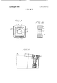
- FIG. 3 is a plan view of an insert of the type shown in FIG. 2 but having cutting edges on both broad faces.
- FIG. 3a shows a sectional view along line A A in FIG. 3.
- FIG. 4 is a view of the insert according to FIG. 3 as fitted in a tool holder together with an anvil.
- FIG. 5 shows a part of an insert according to FIG. I in working position illustrating the chip breaking process and the wear of the insert at a low amount of feed.
- FIG. 6 shows a part of the insert according to FIGS. 2 and 3 in working position against a work piece and illustrates the chip breaking process and the wear of the insert at a low feed.
- FIG. 7 shows part of an insert according to FIG. I in working position against a work piece and illustrates the chip breaking process and the wear of the insert at a high feed.
- FIG. 8 shows an insert according to FIGS. 2 and 3 in working position against a work piece and illustrates the chip breaking process and the wear of the insert at a high speed.
- FIGS. 9a, 9b, 9c, 9d and 9e illustrate examples of various embodiments of the insert within the scope of the present invention.
- Inserts with moulded chip breaker of the type shown in FIG. I are known in various designs.
- the dimension 1 in FIG. Ia varies as to its magnitude and can be positive as well as negative i.e. lie above as well as below the cutting edge.
- the dimension b varies.
- FIG. 2 is illustrated as an example of the invention a square insert differing as to its design from the insert according to FIG. I in that the inner plane 5 adjacent to the chip groove 2 is divided into four plane surfaces 51, 52, 53 and 54, which are inclined downwardly to the insert centre 11 at an angle a. See FIG. 2a.
- the angle a has been chosen equal to the negative inclination of the insert when the same is fitted in a tool holder I2 as illustrated in FIG. 4. Within certain limits this angle a can be further increased whereby an increased effect is attained.
- FIG. 6 is shown how the depth of the chip groove increases by a lesser degree than according to the prior art insert of FIG. 5.
- the dimension I in FIG. 5 has no equivalent in FIG. 6 where the plane 5 adjacent to the chip groove is horizontal.
- the design according to FIG. 6 thus implies a reduction of the chip breaking work and a reduction of the contact surface between chip and insert and thus a reduced detrimental effect.
- FIG. 8 is shown how the contact surface between chip and insert increases to a lesser degree during the wear period than what is shown in FIG. 7.
- the angle a contributes also in this case to a smaller contact surface and less heat transfer from chip to insert.
- FIG. 3 shows an insert according to the invention having cutting edges on both of its broad faces. in other respects the design is the same as for the insert according to FIG. 2.
- FIGS. 9a. 9b, 9c, 9d and 9e the design of the present invention can of course also be applied to inserts for positive cutting rake angles.
- a cutting insert of regular polygonal form having: broad top and bottom surfaces with interconnecting side faces; a cutting edge at the intersection of said side faces with at least one of said broad surfaces; and a chip breaker in the form of a groove provided for each said cutting edge.
- said chip breaker groove being in said at least one broad surface of the insert and extending longitudinally along the cutting edge between the cutting edge and the center of the insert;
- the central region of the insert being formed by and including a plurality of planar surfaces, each of which slopes downwardly toward the other of said broad surfaces from the inner edge of the chip breaker groove and extends to a central portion of the insert;
- planar surfaces extending between lines formed by the bisectors from the insert corners to the geometric center of the insert.
- Insert according to claim 1 having a through hole extending through the center thereof and extending through said broad surfaces.
Abstract
An indexable insert for chip cutting machining has a chip breaking groove along each cutting edge on at least one broad face thereof. The inner edge of the chip breaking groove lies on a level with or ahead of (in the cutting direction) the cutting edge, and the broad face of the insert, inside of each cutting edge chip breaking groove, forms a substantially flat plane inclined downwardly from the groove edge towards the insert center, to thereby minimize the contact area between chip and insert, thereby reducing the transfer of heat from the chip to the insert and improving the service durability of the insert.
Description
United States Patent [1 1 Gustafson et al.
[54] INDEXABLE CUTTING INSERT [75] Inventors: Manfred W. Gustafson; S. Helge Wilhack; Rune Ljungqvist, all of Fagersta, Sweden [73] Assignee: SECO Tools AB, Fagersta. Sweden [22] Filed: Nov. 8, I972 [21] Appl. No.: 304,8
[30] Foreign Application Priority Data Nov. I2. I97! Sweden l4490/7l [52] U.S. Cl 29/95 R [5|] Int. Cl 326d 1/00 [58] Field of Search 29/95. 96
[56] References Cited UNITED STATES PATENTS 2,677.l7() 5/1954 Kuns et al 29/95 2,870,523 H1959 Richard 3,381,349 5/]968 Newcomer..... 3,395,434 8/l968 Wirfelt Apr. s, 1975 3.792.5I5 2/l974 Lundgrcn 29/95 FOREIGN PATENTS OR APPLICATIONS 383.423 l/l923 Germany 29/95 Primary Examiner-Andrew R. Juhasz Assistant Examiner-W. R. Briggs Arlorney, Agent. or Firm-Flynn 8L Frishauf [57] ABSTRACT An indexable insert for chip cutting machining has a chip breaking groove along each cutting edge on at least one broad face thereof. The inner edge of the chip breaking groove lies on a level with or ahead of (in the cutting direction) the cutting edge, and the broad face of the insert, inside of each cutting edge chip breaking groove. forms a substantially flat plane inclined downwardly from the groove edge towards the insert center, to thereby minimize the contact area between chip and insert, thereby reducing the transfer of heat from the chip to the insert and improving the service durability of the insert.
4 Claims, l6 Drawing Figures PATENT EUAPR 8l975 SHIT 2 OF 5 IN DEXABLE CUTTING INSERT The present invention refers to an indexable insert, and more particularly to a through hole insert for chip cutting machining of the type including a moulded in chip breaker, i.e.. an insert having a groove moulded in or ground in along each cutting edge, and which groove serves to break the chips to a manageable size.
Such inserts with moulded in chip breakers of known design correspond substantially to a common insert for negative or positive cutting rake angle with the exception of the chip breaker groove along the cutting edge.
The object of the present invention is to provide an insert with a moulded in chip breaker having such a configuration that the contact area between chip and insert is a minimum whereby less heat is transferred from the chip to the insert and whereby a favourable effect is attained as to the service durability of the insert. Moreover the design of the insert has a favourable effect on the profile that the chip groove is worn at low rate of feed.
SUMMARY OF THE INVENTION The insert according to the invention is characterized in that the broadside of the insert inside the chip breaking groove of each cutting edge constitutes a substantially flat plane which is inclined downwardly towards the insert centre.
Embodiments of the insert according to the invention are described in detail in the following specification with references to the attached drawings.
FIG. 1 is a plan view of a known design of a through hole insert with a moulded in chip breaker designed for negative cutting rake angle.
FIG. la is an enlarged sectional view along line A A in FIG. 1.
FIG. 2 is a plan view of an insert according to the present invention for negative cutting rake angle.
FIG. 2a is an enlarged sectional view along line A A in FIG. 2.
FIG. 3 is a plan view of an insert of the type shown in FIG. 2 but having cutting edges on both broad faces.
FIG. 3a shows a sectional view along line A A in FIG. 3.
FIG. 4 is a view of the insert according to FIG. 3 as fitted in a tool holder together with an anvil.
FIG. 5 shows a part of an insert according to FIG. I in working position illustrating the chip breaking process and the wear of the insert at a low amount of feed.
FIG. 6 shows a part of the insert according to FIGS. 2 and 3 in working position against a work piece and illustrates the chip breaking process and the wear of the insert at a low feed.
FIG. 7 shows part of an insert according to FIG. I in working position against a work piece and illustrates the chip breaking process and the wear of the insert at a high feed.
FIG. 8 shows an insert according to FIGS. 2 and 3 in working position against a work piece and illustrates the chip breaking process and the wear of the insert at a high speed.
FIGS. 9a, 9b, 9c, 9d and 9e illustrate examples of various embodiments of the insert within the scope of the present invention.
DETAILED DESCRIPTION OF DRAWINGS Inserts with moulded chip breaker of the type shown in FIG. I are known in various designs. The dimension 1 in FIG. Ia varies as to its magnitude and can be positive as well as negative i.e. lie above as well as below the cutting edge. Moreover the dimension b varies.
When an insert with moulded in chip breaker according to FIG. I works in a long chipping material with a low amount of feed the chips 4 from the work piece 3 follow the chip groove 2 on the insert I in the manner illustrated in FIG. 5. At successively increased feed the chips 4 will adopt a more straight shape as illustrated in FIG. 7. As shown in FIG. 7, the chip groove 2 then successively goes out of action at the same time as the chip breaking work is taken over by the adjacent plane 5 which forms an angle of to the insert clearance face 7 and which is parallel to the insert cutting edge 8.
During the successive wear of the insert according to FIG. 1 two processes which are unfavourable for the service durability of the insert appear. When working with a low feed as illustrated in FIG. 5 the chip groove 2 is worn down successively to the surface 9 and thus to a greater depth i.e., from h to h, and a larger width i.e., from b to 12.. Due to this wear of groove 2, the Contact area between chip and chip groove is increased at the same time as the ratio between the depth and width of the chip groove is changed in a manner that contributes to an increased chip breaking work. The increased chip breaking work raises the temperature of the chips and of the cutting insert at the same time as the increased contact area allows greater heat transfer from chip to insert. this combination of circumstances being together a drawback for the service durability of the insert.
At a high feed when the chips have the shape shown in FIG. 7 a similar effect appears. When the shape of the chips at an increased feed approaches the tangent to the cutting insert inner plane 5 a rapidly growing wear surface 10 arises contributing to an increased heat transfer from chip to insert. L, in FIG. 7 indicates the magnitude of the wear.
The insert according to the invention does reduce the drawbacks elucidated above. In FIG. 2 is illustrated as an example of the invention a square insert differing as to its design from the insert according to FIG. I in that the inner plane 5 adjacent to the chip groove 2 is divided into four plane surfaces 51, 52, 53 and 54, which are inclined downwardly to the insert centre 11 at an angle a. See FIG. 2a. In the specification and on the drawings the angle a has been chosen equal to the negative inclination of the insert when the same is fitted in a tool holder I2 as illustrated in FIG. 4. Within certain limits this angle a can be further increased whereby an increased effect is attained.
In FIG. 6 is shown how the depth of the chip groove increases by a lesser degree than according to the prior art insert of FIG. 5. The dimension I in FIG. 5 has no equivalent in FIG. 6 where the plane 5 adjacent to the chip groove is horizontal. The design according to FIG. 6 thus implies a reduction of the chip breaking work and a reduction of the contact surface between chip and insert and thus a reduced detrimental effect.
In FIG. 8 is shown how the contact surface between chip and insert increases to a lesser degree during the wear period than what is shown in FIG. 7. The angle a contributes also in this case to a smaller contact surface and less heat transfer from chip to insert.
FIG. 3 shows an insert according to the invention having cutting edges on both of its broad faces. in other respects the design is the same as for the insert according to FIG. 2.
Besides the embodiments shown in FIGS. 9a. 9b, 9c, 9d and 9e the design of the present invention can of course also be applied to inserts for positive cutting rake angles.
We claim:
1. A cutting insert of regular polygonal form having: broad top and bottom surfaces with interconnecting side faces; a cutting edge at the intersection of said side faces with at least one of said broad surfaces; and a chip breaker in the form of a groove provided for each said cutting edge. said chip breaker groove being in said at least one broad surface of the insert and extending longitudinally along the cutting edge between the cutting edge and the center of the insert;
characterized in that:
the central region of the insert being formed by and including a plurality of planar surfaces, each of which slopes downwardly toward the other of said broad surfaces from the inner edge of the chip breaker groove and extends to a central portion of the insert; and
said planar surfaces extending between lines formed by the bisectors from the insert corners to the geometric center of the insert.
2. Insert according to claim 1 characterized in that three of said downwardly sloping planar surfaces are formed in said central region and that said downwardly sloping planar surfaces form congruent triangles.
3. Insert according to claim 1, characterized in that a plurality of said downwardly sloping planar surfaces are formed in said central region and that said downwardly sloping planar surfaces form triangles which are congruent in pairs.
4. Insert according to claim 1 having a through hole extending through the center thereof and extending through said broad surfaces.
Claims (4)
1. A cutting insert of regular polygonal form having: broad top and bottom surfaces with interconnecting side faces; a cutting edge at the intersection of said side faces with at least one of said broad surfaces; and a chip breaker in the form of a groove provided for each said cutting edge, said chip breaker groove being in said at least one broad surface of the insert and extending longitudinally along the cutting edge between the cutting edge and the center of the insert; characterized in that: the central region of the insert being formed by and including a plurality of planar surfaces, each of which slopes downwardly toward the other of said broad surfaces from the inner edge of the chip breaker groove and extends to a central portion of the insert; and said planar surfaces extending between lines formed by the bisectors from the insert corners to the geometric center of the insert.
2. Insert according to claim 1 characterized in that three of said downwardly sloping planar surfaces are formed in said central region and that said downwardly sloping planar surfaces form congruent triangles.
3. Insert according to claim 1, characterized in that a plurality of said downwardly sloping planar surfaces are formed in said central region and that said downwardly sloping planar surfaces form triangles which are congruent in pairs.
4. Insert according to claim 1 having a through hole extending through the center thereof and extending through said broad surfaces.
Applications Claiming Priority (1)
| Application Number | Priority Date | Filing Date | Title |
|---|---|---|---|
| SE7114490A SE380751B (en) | 1971-11-12 | 1971-11-12 | FRIENDS |
Publications (1)
| Publication Number | Publication Date |
|---|---|
| US3875663A true US3875663A (en) | 1975-04-08 |
Family
ID=20299190
Family Applications (1)
| Application Number | Title | Priority Date | Filing Date |
|---|---|---|---|
| US304811A Expired - Lifetime US3875663A (en) | 1971-11-12 | 1972-11-08 | Indexable cutting insert |
Country Status (6)
| Country | Link |
|---|---|
| US (1) | US3875663A (en) |
| DE (1) | DE2254270A1 (en) |
| FR (1) | FR2160197A5 (en) |
| GB (1) | GB1413167A (en) |
| IT (1) | IT970330B (en) |
| SE (1) | SE380751B (en) |
Cited By (18)
| Publication number | Priority date | Publication date | Assignee | Title |
|---|---|---|---|---|
| US4044439A (en) * | 1974-06-14 | 1977-08-30 | Ugine Carbone | Cutting plate with chip breakers |
| US4312250A (en) * | 1980-01-16 | 1982-01-26 | Yankoff Gerald K | Cutting insert and method of machining therewith |
| US4569619A (en) * | 1983-02-14 | 1986-02-11 | J. P. Tool Limited | Machine tool cutter |
| DE3544236A1 (en) * | 1984-12-18 | 1986-06-19 | Colgate-Palmolive Co., New York, N.Y. | CONCENTRATED, AQUEOUS, SINGLE-PHASE, HOMOGENEOUS BUILDER CONTAINING, LIQUID DETERGENT COMPOSITION |
| US4616963A (en) * | 1981-07-10 | 1986-10-14 | Feldmuhle Aktiengesellschaft | Cutting tip for cutting-tools |
| US4710069A (en) * | 1985-07-09 | 1987-12-01 | Seco Tools Ab | Cutting insert for chip forming machining |
| US4720217A (en) * | 1981-05-19 | 1988-01-19 | Stellram S.A. | Cutter bit for machining by chip removal |
| US4755086A (en) * | 1987-10-23 | 1988-07-05 | Gte Valenite Corporation | Cutting insert |
| EP0362171A2 (en) * | 1988-09-26 | 1990-04-04 | Sandvik Aktiebolag | Double-sided cutting insert |
| US5207748A (en) * | 1991-11-12 | 1993-05-04 | Valenite Inc. | High productivity insert |
| US5342151A (en) * | 1992-01-20 | 1994-08-30 | Iscar Ltd. | Cutting insert having a circular cutting edge with a chip former |
| US20110103905A1 (en) * | 2009-11-03 | 2011-05-05 | Kennametal Inc. | Round Cutting Insert With Anti-Rotation Feature |
| US20120251250A1 (en) * | 2011-03-28 | 2012-10-04 | Kennametal Inc. | Round cutting insert with reverse anti-rotation feature |
| US20130279994A1 (en) * | 2012-04-24 | 2013-10-24 | Kennametal Inc. | Indexable circular cutting insert |
| US8613576B2 (en) | 2008-08-14 | 2013-12-24 | Kennametal Inc. | Indexable cutting insert |
| USD709110S1 (en) | 2012-04-24 | 2014-07-15 | Kennametal Inc. | Cutting insert |
| US20150071717A1 (en) * | 2013-09-11 | 2015-03-12 | Kennametal Inc. | Cutting insert with finishing and roughing cutting edges |
| US9475138B2 (en) | 2014-01-22 | 2016-10-25 | Kennametal Inc. | Cutting tool having insert pocket with cantilevered member |
Families Citing this family (6)
| Publication number | Priority date | Publication date | Assignee | Title |
|---|---|---|---|---|
| IT1145995B (en) * | 1981-01-08 | 1986-11-12 | Iscar Ltd | METAL CUTTING TOOL PROVIDED WITH REPLACEABLE INSERT |
| SE454420B (en) * | 1984-05-14 | 1988-05-02 | Santrade Ltd | HAPPENS FOR LONG, SLIPPING OR COPYRUPTING |
| SE445094B (en) * | 1984-10-10 | 1986-06-02 | Santrade Ltd | HAPPENS WITH STUDYTOR ON ITS SIDE |
| CH667407A5 (en) * | 1986-03-27 | 1988-10-14 | Stellram Sa | STRAWBERRY WITH REMOVABLE CUTTING INSERTS. |
| DE3819131A1 (en) * | 1988-06-06 | 1989-12-07 | Mapal Fab Praezision | CUTTING INSERT FOR THE FINISHING, IN PARTICULAR OF HOLES |
| US5807031A (en) * | 1995-03-10 | 1998-09-15 | Mitsubishi Materials Corp. | Throw-away tip and throw-away type cutter |
Citations (5)
| Publication number | Priority date | Publication date | Assignee | Title |
|---|---|---|---|---|
| US2677170A (en) * | 1951-06-16 | 1954-05-04 | Robert J Kuns | Cutting bit |
| US2870523A (en) * | 1956-08-10 | 1959-01-27 | Theophile J La Lime | Cutting tools |
| US3381349A (en) * | 1966-04-25 | 1968-05-07 | Newcomer Prod Inc | Cutting tool |
| US3395434A (en) * | 1966-06-01 | 1968-08-06 | Sandvikens Jernverks Ab | Cutting insert for chip cutting machining |
| US3792515A (en) * | 1971-10-27 | 1974-02-19 | Sandvikens Jernverks Ab | Single-faced cutting insert |
-
1971
- 1971-11-12 SE SE7114490A patent/SE380751B/en unknown
-
1972
- 1972-10-16 GB GB4755772A patent/GB1413167A/en not_active Expired
- 1972-11-06 DE DE2254270A patent/DE2254270A1/en not_active Withdrawn
- 1972-11-08 US US304811A patent/US3875663A/en not_active Expired - Lifetime
- 1972-11-09 IT IT31444/72A patent/IT970330B/en active
- 1972-11-10 FR FR7240039A patent/FR2160197A5/fr not_active Expired
Patent Citations (5)
| Publication number | Priority date | Publication date | Assignee | Title |
|---|---|---|---|---|
| US2677170A (en) * | 1951-06-16 | 1954-05-04 | Robert J Kuns | Cutting bit |
| US2870523A (en) * | 1956-08-10 | 1959-01-27 | Theophile J La Lime | Cutting tools |
| US3381349A (en) * | 1966-04-25 | 1968-05-07 | Newcomer Prod Inc | Cutting tool |
| US3395434A (en) * | 1966-06-01 | 1968-08-06 | Sandvikens Jernverks Ab | Cutting insert for chip cutting machining |
| US3792515A (en) * | 1971-10-27 | 1974-02-19 | Sandvikens Jernverks Ab | Single-faced cutting insert |
Cited By (24)
| Publication number | Priority date | Publication date | Assignee | Title |
|---|---|---|---|---|
| US4044439A (en) * | 1974-06-14 | 1977-08-30 | Ugine Carbone | Cutting plate with chip breakers |
| US4312250A (en) * | 1980-01-16 | 1982-01-26 | Yankoff Gerald K | Cutting insert and method of machining therewith |
| US4720217A (en) * | 1981-05-19 | 1988-01-19 | Stellram S.A. | Cutter bit for machining by chip removal |
| US4616963A (en) * | 1981-07-10 | 1986-10-14 | Feldmuhle Aktiengesellschaft | Cutting tip for cutting-tools |
| US4569619A (en) * | 1983-02-14 | 1986-02-11 | J. P. Tool Limited | Machine tool cutter |
| DE3544236A1 (en) * | 1984-12-18 | 1986-06-19 | Colgate-Palmolive Co., New York, N.Y. | CONCENTRATED, AQUEOUS, SINGLE-PHASE, HOMOGENEOUS BUILDER CONTAINING, LIQUID DETERGENT COMPOSITION |
| US4710069A (en) * | 1985-07-09 | 1987-12-01 | Seco Tools Ab | Cutting insert for chip forming machining |
| US4755086A (en) * | 1987-10-23 | 1988-07-05 | Gte Valenite Corporation | Cutting insert |
| EP0362171A2 (en) * | 1988-09-26 | 1990-04-04 | Sandvik Aktiebolag | Double-sided cutting insert |
| EP0362171A3 (en) * | 1988-09-26 | 1990-08-22 | Sandvik Aktiebolag | Double-sided cutting insert |
| US5207748A (en) * | 1991-11-12 | 1993-05-04 | Valenite Inc. | High productivity insert |
| US5342151A (en) * | 1992-01-20 | 1994-08-30 | Iscar Ltd. | Cutting insert having a circular cutting edge with a chip former |
| US8613576B2 (en) | 2008-08-14 | 2013-12-24 | Kennametal Inc. | Indexable cutting insert |
| US20110103905A1 (en) * | 2009-11-03 | 2011-05-05 | Kennametal Inc. | Round Cutting Insert With Anti-Rotation Feature |
| US8573903B2 (en) | 2009-11-03 | 2013-11-05 | Kennametal Inc. | Round cutting insert with anti-rotation feature |
| US20120251250A1 (en) * | 2011-03-28 | 2012-10-04 | Kennametal Inc. | Round cutting insert with reverse anti-rotation feature |
| US8657539B2 (en) * | 2011-03-28 | 2014-02-25 | Kennametal Inc. | Round cutting insert with reverse anti-rotation feature |
| US20130279994A1 (en) * | 2012-04-24 | 2013-10-24 | Kennametal Inc. | Indexable circular cutting insert |
| USD709110S1 (en) | 2012-04-24 | 2014-07-15 | Kennametal Inc. | Cutting insert |
| US8858130B2 (en) * | 2012-04-24 | 2014-10-14 | Kennametal Inc. | Indexable circular cutting insert |
| US9505065B2 (en) | 2012-04-24 | 2016-11-29 | Kennametal Inc. | Indexable circular cutting insert |
| US20150071717A1 (en) * | 2013-09-11 | 2015-03-12 | Kennametal Inc. | Cutting insert with finishing and roughing cutting edges |
| US9205499B2 (en) * | 2013-09-11 | 2015-12-08 | Kennametal Inc. | Cutting insert with finishing and roughing cutting edges |
| US9475138B2 (en) | 2014-01-22 | 2016-10-25 | Kennametal Inc. | Cutting tool having insert pocket with cantilevered member |
Also Published As
| Publication number | Publication date |
|---|---|
| DE2254270A1 (en) | 1973-05-17 |
| FR2160197A5 (en) | 1973-06-22 |
| GB1413167A (en) | 1975-11-05 |
| SE380751B (en) | 1975-11-17 |
| IT970330B (en) | 1974-04-10 |
Similar Documents
| Publication | Publication Date | Title |
|---|---|---|
| US3875663A (en) | Indexable cutting insert | |
| CA1299852C (en) | Indexable cutting insert | |
| US5333972A (en) | Special boring insert | |
| US4618296A (en) | Cutting tool and insert therefor | |
| US4597695A (en) | Face milling apparatus with eight-edged insert | |
| US5577867A (en) | Cutter insert | |
| EP1850992B1 (en) | A cutting insert with a varying chamfer angle at the nose cutting edge | |
| US5876160A (en) | Milling with insert having cutting-edge land of width increasing with depth of cut | |
| EP1855828B1 (en) | A cutting insert with a small chamfer angle at the nose cutting edge | |
| US5460464A (en) | Cutting insert | |
| US5007775A (en) | Cutting insert for chip removing machining | |
| US6196771B1 (en) | Face-milling method and apparatus | |
| EP0577011A1 (en) | Throw away insert and face milling cutter | |
| US3866282A (en) | Cutting insert | |
| EP0589265B1 (en) | High sheer, ultra light duty insert | |
| JP2909104B2 (en) | Cutter plate for precision machining and method of manufacturing the same | |
| CN1116835A (en) | Cutting insert with twisted chip surface | |
| US5000626A (en) | Cutting insert for low ranges of feed and depth of cut | |
| WO1998007543A9 (en) | Insert having variable width land | |
| JP6898948B2 (en) | Turning insert | |
| US5067858A (en) | Multiple faced cutter insert | |
| CA1217926A (en) | Cutting insert with means for simultaneously removing a plurality of chips | |
| US6604893B2 (en) | Cutting insert with wiper | |
| US6641337B1 (en) | Cutting insert and tool having a cutting insert | |
| CA1101201A (en) | Cutting insert |