US3948810A - Monolithic catalyst support member - Google Patents
Monolithic catalyst support member Download PDFInfo
- Publication number
- US3948810A US3948810A US05/491,007 US49100774A US3948810A US 3948810 A US3948810 A US 3948810A US 49100774 A US49100774 A US 49100774A US 3948810 A US3948810 A US 3948810A
- Authority
- US
- United States
- Prior art keywords
- members
- support member
- catalyst support
- sheet members
- ceramic
- Prior art date
- Legal status (The legal status is an assumption and is not a legal conclusion. Google has not performed a legal analysis and makes no representation as to the accuracy of the status listed.)
- Expired - Lifetime
Links
- 239000003054 catalyst Substances 0.000 title claims abstract description 31
- 239000000919 ceramic Substances 0.000 claims abstract description 24
- 239000008188 pellet Substances 0.000 claims abstract description 13
- 239000000463 material Substances 0.000 claims abstract description 12
- 239000012530 fluid Substances 0.000 claims abstract description 9
- 239000011819 refractory material Substances 0.000 claims abstract description 7
- 229910010293 ceramic material Inorganic materials 0.000 claims description 8
- 238000006243 chemical reaction Methods 0.000 claims description 8
- 239000011248 coating agent Substances 0.000 claims description 8
- 238000000576 coating method Methods 0.000 claims description 8
- 238000004804 winding Methods 0.000 claims description 5
- 239000000203 mixture Substances 0.000 claims description 4
- 229910052809 inorganic oxide Inorganic materials 0.000 claims description 3
- 238000007254 oxidation reaction Methods 0.000 claims description 3
- 230000003647 oxidation Effects 0.000 claims description 2
- PNEYBMLMFCGWSK-UHFFFAOYSA-N Alumina Chemical compound [O-2].[O-2].[O-2].[Al+3].[Al+3] PNEYBMLMFCGWSK-UHFFFAOYSA-N 0.000 abstract description 4
- HEHRHMRHPUNLIR-UHFFFAOYSA-N aluminum;hydroxy-[hydroxy(oxo)silyl]oxy-oxosilane;lithium Chemical compound [Li].[Al].O[Si](=O)O[Si](O)=O.O[Si](=O)O[Si](O)=O HEHRHMRHPUNLIR-UHFFFAOYSA-N 0.000 abstract description 2
- 229910052878 cordierite Inorganic materials 0.000 abstract description 2
- JSKIRARMQDRGJZ-UHFFFAOYSA-N dimagnesium dioxido-bis[(1-oxido-3-oxo-2,4,6,8,9-pentaoxa-1,3-disila-5,7-dialuminabicyclo[3.3.1]nonan-7-yl)oxy]silane Chemical compound [Mg++].[Mg++].[O-][Si]([O-])(O[Al]1O[Al]2O[Si](=O)O[Si]([O-])(O1)O2)O[Al]1O[Al]2O[Si](=O)O[Si]([O-])(O1)O2 JSKIRARMQDRGJZ-UHFFFAOYSA-N 0.000 abstract description 2
- 239000000395 magnesium oxide Substances 0.000 abstract description 2
- CPLXHLVBOLITMK-UHFFFAOYSA-N magnesium oxide Inorganic materials [Mg]=O CPLXHLVBOLITMK-UHFFFAOYSA-N 0.000 abstract description 2
- 229910052863 mullite Inorganic materials 0.000 abstract description 2
- 229910052670 petalite Inorganic materials 0.000 abstract description 2
- 241000264877 Hippospongia communis Species 0.000 description 25
- 239000007789 gas Substances 0.000 description 16
- 230000003197 catalytic effect Effects 0.000 description 13
- 239000006187 pill Substances 0.000 description 8
- 230000000694 effects Effects 0.000 description 6
- 238000000034 method Methods 0.000 description 6
- VYPSYNLAJGMNEJ-UHFFFAOYSA-N Silicium dioxide Chemical compound O=[Si]=O VYPSYNLAJGMNEJ-UHFFFAOYSA-N 0.000 description 4
- 229910052751 metal Inorganic materials 0.000 description 4
- 239000002184 metal Substances 0.000 description 4
- XEEYBQQBJWHFJM-UHFFFAOYSA-N Iron Chemical compound [Fe] XEEYBQQBJWHFJM-UHFFFAOYSA-N 0.000 description 3
- 230000008901 benefit Effects 0.000 description 3
- 150000002739 metals Chemical class 0.000 description 3
- MWUXSHHQAYIFBG-UHFFFAOYSA-N nitrogen oxide Inorganic materials O=[N] MWUXSHHQAYIFBG-UHFFFAOYSA-N 0.000 description 3
- 239000002245 particle Substances 0.000 description 3
- 239000000376 reactant Substances 0.000 description 3
- 230000001603 reducing effect Effects 0.000 description 3
- CURLTUGMZLYLDI-UHFFFAOYSA-N Carbon dioxide Chemical compound O=C=O CURLTUGMZLYLDI-UHFFFAOYSA-N 0.000 description 2
- PXHVJJICTQNCMI-UHFFFAOYSA-N Nickel Chemical compound [Ni] PXHVJJICTQNCMI-UHFFFAOYSA-N 0.000 description 2
- KDLHZDBZIXYQEI-UHFFFAOYSA-N Palladium Chemical compound [Pd] KDLHZDBZIXYQEI-UHFFFAOYSA-N 0.000 description 2
- 230000015572 biosynthetic process Effects 0.000 description 2
- 230000001473 noxious effect Effects 0.000 description 2
- BASFCYQUMIYNBI-UHFFFAOYSA-N platinum Chemical compound [Pt] BASFCYQUMIYNBI-UHFFFAOYSA-N 0.000 description 2
- 239000000377 silicon dioxide Substances 0.000 description 2
- 239000002912 waste gas Substances 0.000 description 2
- IJGRMHOSHXDMSA-UHFFFAOYSA-N Atomic nitrogen Chemical compound N#N IJGRMHOSHXDMSA-UHFFFAOYSA-N 0.000 description 1
- VYZAMTAEIAYCRO-UHFFFAOYSA-N Chromium Chemical compound [Cr] VYZAMTAEIAYCRO-UHFFFAOYSA-N 0.000 description 1
- RYGMFSIKBFXOCR-UHFFFAOYSA-N Copper Chemical compound [Cu] RYGMFSIKBFXOCR-UHFFFAOYSA-N 0.000 description 1
- QPLDLSVMHZLSFG-UHFFFAOYSA-N Copper oxide Chemical compound [Cu]=O QPLDLSVMHZLSFG-UHFFFAOYSA-N 0.000 description 1
- 239000005751 Copper oxide Substances 0.000 description 1
- KJTLSVCANCCWHF-UHFFFAOYSA-N Ruthenium Chemical compound [Ru] KJTLSVCANCCWHF-UHFFFAOYSA-N 0.000 description 1
- BPYJYOWCIUCOEE-UHFFFAOYSA-N [Co]=O.[Cu]=O Chemical compound [Co]=O.[Cu]=O BPYJYOWCIUCOEE-UHFFFAOYSA-N 0.000 description 1
- 238000005299 abrasion Methods 0.000 description 1
- 239000000654 additive Substances 0.000 description 1
- 230000000996 additive effect Effects 0.000 description 1
- 229910052788 barium Inorganic materials 0.000 description 1
- DSAJWYNOEDNPEQ-UHFFFAOYSA-N barium atom Chemical compound [Ba] DSAJWYNOEDNPEQ-UHFFFAOYSA-N 0.000 description 1
- 239000001569 carbon dioxide Substances 0.000 description 1
- 229910002092 carbon dioxide Inorganic materials 0.000 description 1
- 229910052804 chromium Inorganic materials 0.000 description 1
- 239000011651 chromium Substances 0.000 description 1
- 229910017052 cobalt Inorganic materials 0.000 description 1
- 239000010941 cobalt Substances 0.000 description 1
- GUTLYIVDDKVIGB-UHFFFAOYSA-N cobalt atom Chemical compound [Co] GUTLYIVDDKVIGB-UHFFFAOYSA-N 0.000 description 1
- 238000010276 construction Methods 0.000 description 1
- 230000008602 contraction Effects 0.000 description 1
- 229910052802 copper Inorganic materials 0.000 description 1
- 239000010949 copper Substances 0.000 description 1
- 229910000431 copper oxide Inorganic materials 0.000 description 1
- 229910002106 crystalline ceramic Inorganic materials 0.000 description 1
- 239000011222 crystalline ceramic Substances 0.000 description 1
- UAMZXLIURMNTHD-UHFFFAOYSA-N dialuminum;magnesium;oxygen(2-) Chemical compound [O-2].[O-2].[O-2].[O-2].[Mg+2].[Al+3].[Al+3] UAMZXLIURMNTHD-UHFFFAOYSA-N 0.000 description 1
- 230000008030 elimination Effects 0.000 description 1
- 238000003379 elimination reaction Methods 0.000 description 1
- 238000001125 extrusion Methods 0.000 description 1
- 229910052742 iron Inorganic materials 0.000 description 1
- 238000004519 manufacturing process Methods 0.000 description 1
- 229910044991 metal oxide Inorganic materials 0.000 description 1
- 150000004706 metal oxides Chemical class 0.000 description 1
- 229910052759 nickel Inorganic materials 0.000 description 1
- JCXJVPUVTGWSNB-UHFFFAOYSA-N nitrogen dioxide Inorganic materials O=[N]=O JCXJVPUVTGWSNB-UHFFFAOYSA-N 0.000 description 1
- 230000008520 organization Effects 0.000 description 1
- 230000001590 oxidative effect Effects 0.000 description 1
- 238000012856 packing Methods 0.000 description 1
- 229910052763 palladium Inorganic materials 0.000 description 1
- 230000000737 periodic effect Effects 0.000 description 1
- 239000003208 petroleum Substances 0.000 description 1
- 229910052697 platinum Inorganic materials 0.000 description 1
- 239000000843 powder Substances 0.000 description 1
- 238000002360 preparation method Methods 0.000 description 1
- 230000010349 pulsation Effects 0.000 description 1
- 229910052703 rhodium Inorganic materials 0.000 description 1
- 239000010948 rhodium Substances 0.000 description 1
- MHOVAHRLVXNVSD-UHFFFAOYSA-N rhodium atom Chemical compound [Rh] MHOVAHRLVXNVSD-UHFFFAOYSA-N 0.000 description 1
- 229910052707 ruthenium Inorganic materials 0.000 description 1
- 229910052851 sillimanite Inorganic materials 0.000 description 1
- -1 spondumene Chemical compound 0.000 description 1
- 239000000126 substance Substances 0.000 description 1
- 239000000725 suspension Substances 0.000 description 1
- 229910052720 vanadium Inorganic materials 0.000 description 1
- LEONUFNNVUYDNQ-UHFFFAOYSA-N vanadium atom Chemical compound [V] LEONUFNNVUYDNQ-UHFFFAOYSA-N 0.000 description 1
- 229910052845 zircon Inorganic materials 0.000 description 1
- GFQYVLUOOAAOGM-UHFFFAOYSA-N zirconium(iv) silicate Chemical compound [Zr+4].[O-][Si]([O-])([O-])[O-] GFQYVLUOOAAOGM-UHFFFAOYSA-N 0.000 description 1
Images
Classifications
-
- B01J35/56—
-
- B—PERFORMING OPERATIONS; TRANSPORTING
- B01—PHYSICAL OR CHEMICAL PROCESSES OR APPARATUS IN GENERAL
- B01D—SEPARATION
- B01D53/00—Separation of gases or vapours; Recovering vapours of volatile solvents from gases; Chemical or biological purification of waste gases, e.g. engine exhaust gases, smoke, fumes, flue gases, aerosols
- B01D53/34—Chemical or biological purification of waste gases
- B01D53/74—General processes for purification of waste gases; Apparatus or devices specially adapted therefor
- B01D53/86—Catalytic processes
-
- B—PERFORMING OPERATIONS; TRANSPORTING
- B01—PHYSICAL OR CHEMICAL PROCESSES OR APPARATUS IN GENERAL
- B01J—CHEMICAL OR PHYSICAL PROCESSES, e.g. CATALYSIS OR COLLOID CHEMISTRY; THEIR RELEVANT APPARATUS
- B01J35/00—Catalysts, in general, characterised by their form or physical properties
-
- B01J35/30—
-
- F—MECHANICAL ENGINEERING; LIGHTING; HEATING; WEAPONS; BLASTING
- F01—MACHINES OR ENGINES IN GENERAL; ENGINE PLANTS IN GENERAL; STEAM ENGINES
- F01N—GAS-FLOW SILENCERS OR EXHAUST APPARATUS FOR MACHINES OR ENGINES IN GENERAL; GAS-FLOW SILENCERS OR EXHAUST APPARATUS FOR INTERNAL COMBUSTION ENGINES
- F01N3/00—Exhaust or silencing apparatus having means for purifying, rendering innocuous, or otherwise treating exhaust
- F01N3/08—Exhaust or silencing apparatus having means for purifying, rendering innocuous, or otherwise treating exhaust for rendering innocuous
- F01N3/10—Exhaust or silencing apparatus having means for purifying, rendering innocuous, or otherwise treating exhaust for rendering innocuous by thermal or catalytic conversion of noxious components of exhaust
- F01N3/24—Exhaust or silencing apparatus having means for purifying, rendering innocuous, or otherwise treating exhaust for rendering innocuous by thermal or catalytic conversion of noxious components of exhaust characterised by constructional aspects of converting apparatus
- F01N3/28—Construction of catalytic reactors
- F01N3/2803—Construction of catalytic reactors characterised by structure, by material or by manufacturing of catalyst support
- F01N3/2825—Ceramics
- F01N3/2828—Ceramic multi-channel monoliths, e.g. honeycombs
-
- F—MECHANICAL ENGINEERING; LIGHTING; HEATING; WEAPONS; BLASTING
- F01—MACHINES OR ENGINES IN GENERAL; ENGINE PLANTS IN GENERAL; STEAM ENGINES
- F01N—GAS-FLOW SILENCERS OR EXHAUST APPARATUS FOR MACHINES OR ENGINES IN GENERAL; GAS-FLOW SILENCERS OR EXHAUST APPARATUS FOR INTERNAL COMBUSTION ENGINES
- F01N3/00—Exhaust or silencing apparatus having means for purifying, rendering innocuous, or otherwise treating exhaust
- F01N3/08—Exhaust or silencing apparatus having means for purifying, rendering innocuous, or otherwise treating exhaust for rendering innocuous
- F01N3/10—Exhaust or silencing apparatus having means for purifying, rendering innocuous, or otherwise treating exhaust for rendering innocuous by thermal or catalytic conversion of noxious components of exhaust
- F01N3/24—Exhaust or silencing apparatus having means for purifying, rendering innocuous, or otherwise treating exhaust for rendering innocuous by thermal or catalytic conversion of noxious components of exhaust characterised by constructional aspects of converting apparatus
- F01N3/28—Construction of catalytic reactors
- F01N3/2803—Construction of catalytic reactors characterised by structure, by material or by manufacturing of catalyst support
- F01N3/2832—Construction of catalytic reactors characterised by structure, by material or by manufacturing of catalyst support granular, e.g. pellets
-
- F—MECHANICAL ENGINEERING; LIGHTING; HEATING; WEAPONS; BLASTING
- F01—MACHINES OR ENGINES IN GENERAL; ENGINE PLANTS IN GENERAL; STEAM ENGINES
- F01N—GAS-FLOW SILENCERS OR EXHAUST APPARATUS FOR MACHINES OR ENGINES IN GENERAL; GAS-FLOW SILENCERS OR EXHAUST APPARATUS FOR INTERNAL COMBUSTION ENGINES
- F01N3/00—Exhaust or silencing apparatus having means for purifying, rendering innocuous, or otherwise treating exhaust
- F01N3/08—Exhaust or silencing apparatus having means for purifying, rendering innocuous, or otherwise treating exhaust for rendering innocuous
- F01N3/10—Exhaust or silencing apparatus having means for purifying, rendering innocuous, or otherwise treating exhaust for rendering innocuous by thermal or catalytic conversion of noxious components of exhaust
- F01N3/24—Exhaust or silencing apparatus having means for purifying, rendering innocuous, or otherwise treating exhaust for rendering innocuous by thermal or catalytic conversion of noxious components of exhaust characterised by constructional aspects of converting apparatus
- F01N3/28—Construction of catalytic reactors
- F01N3/2839—Arrangements for mounting catalyst support in housing, e.g. with means for compensating thermal expansion or vibration
- F01N3/2846—Arrangements for mounting catalyst support in housing, e.g. with means for compensating thermal expansion or vibration specially adapted for granular supports, e.g. pellets
-
- F—MECHANICAL ENGINEERING; LIGHTING; HEATING; WEAPONS; BLASTING
- F01—MACHINES OR ENGINES IN GENERAL; ENGINE PLANTS IN GENERAL; STEAM ENGINES
- F01N—GAS-FLOW SILENCERS OR EXHAUST APPARATUS FOR MACHINES OR ENGINES IN GENERAL; GAS-FLOW SILENCERS OR EXHAUST APPARATUS FOR INTERNAL COMBUSTION ENGINES
- F01N2330/00—Structure of catalyst support or particle filter
- F01N2330/30—Honeycomb supports characterised by their structural details
- F01N2330/38—Honeycomb supports characterised by their structural details flow channels with means to enhance flow mixing,(e.g. protrusions or projections)
-
- Y—GENERAL TAGGING OF NEW TECHNOLOGICAL DEVELOPMENTS; GENERAL TAGGING OF CROSS-SECTIONAL TECHNOLOGIES SPANNING OVER SEVERAL SECTIONS OF THE IPC; TECHNICAL SUBJECTS COVERED BY FORMER USPC CROSS-REFERENCE ART COLLECTIONS [XRACs] AND DIGESTS
- Y10—TECHNICAL SUBJECTS COVERED BY FORMER USPC
- Y10T—TECHNICAL SUBJECTS COVERED BY FORMER US CLASSIFICATION
- Y10T428/00—Stock material or miscellaneous articles
- Y10T428/24—Structurally defined web or sheet [e.g., overall dimension, etc.]
- Y10T428/24149—Honeycomb-like
Definitions
- the present invention relates to a special form of rigid refractory honeycomb or skeletal ceramic type of element which is temperature resistant and sufficiently porous as to provide a support for a catalyst coating.
- the present support element is formed by integrating uniformly sized spheres, or substantially round pellets, between spaced layers of sheet-like members such that the resulting support element will provide a tortuous turbulent flow path for a fluid stream passing between the layers of the element.
- the present special form of refractory member is also of particular value in providing a rigid catalyst support member for use in automobile catalytic converters to treat auto exhaust gases.
- Catalytic materials for chemical and petroleum processing, as well as for auto exhaust gas converters have been prepared in many forms, including powders, balls, small spheres, micor-spheres, shaped pellets, etc., and also have been used in various types of arrangements including: single beds, spaced beds, annular beds, suspensions, and the like. Small spheres in the 1/16 inch to 1/4 inch range are widely used since they are readily prepared commercially to have high surface area, low bulk density and can be coated to have high activity. However, in conducting field testing of automobile exhaust gas catalytic converters, it has been observed that many converters "fail" from catalyst losses due to catalyst breakage and/or attrition.
- the breakage and attrition or abrasion of particles is generally due to the loosening of the catalyst particles in the bed and the resulting relatively free movement of individual particles.
- the looseness may result from catalyst breakage caused by expansion and contraction movements of a metal converter housing as well as from warpage of perforated plates or screens which are used to retain the catalyst in the housing.
- catalyst breakage caused by expansion and contraction movements of a metal converter housing as well as from warpage of perforated plates or screens which are used to retain the catalyst in the housing.
- each skeletal member or element has a multiplicity of straight-through, parallel channels whether having openings from an extrusion operation or passageways formed from the use of corrugated layers.
- the present invention provides a monolithic catalyst support member which comprises in combination, a plurality of spaced apart rigid ceramic sheet members and a multiplicity of substantially round pellets of rigid refractory material affixed to and, in turn, spaced apart between said spaced sheet members, with such round pellets being positioned in a manner other than in non-staggered rows to thereby provide turbulent fluid flow for a stream passing between the sheet members.
- the present invention provides a catalytic converter for effecting the conversion of a waste gas stream, which comprises in combination: (a) a housing with gas inlet means to one end thereof and a gas outlet means from the other end thereof, and (b) at least one rigid refractory honeycomb type of ceramic element with a conversion catalyst coating thereon positioned within said housing to provide for turbulent gas flow therethrough from said gas inlet means to said gas outlet means, with (c) said ceramic element formed of spaced apart sheet members and a multiplicity of substantially round members of rigid refractory material affixed to and, in turn, spaced apart between said spaced sheet members in a manner other than in non-staggered rows, whereby there is a desired resulting turbulent flow for the gas stream passing between the sheet members.
- honeycomb or skeletal structural support materials may comprise alpha-alumina, alumina-silica-magnesia, zirconia-silicate, zircon-mullite, and the like.
- other refractory crystalline ceramic materials which may be formed into honeycombs or rigid skeletal structures and which are utilizable may comprise sillimanite, zircon, petalite, spondumene, cordierite, and alumina-silicates.
- the present improved ceramic honeycomb elements will have both the sheet members and the round pills or spheres provided of the same type of composition, with the same general characteristics of coefficient of expansion, etc., such that the spacing pills will become fused with the sheet-like members and provide a rigid structure.
- the randomly spaced spherical pieces placed between the spaced apart sheet members may be of a hard refractory material other than a ceramic, as long as there is the capability to become fused and fixedly held between the sheet members and not have a greatly different coefficient of expansion.
- catalyst support spheres made from alumina, silica, silica-alumina, alumina-magnesia, etc., or other inorganic oxides, may well be utilized, particularly, catalyst support pills which are of relatively high bulk density or have been hardened or stabilized with additive materials such as barium or other alkaline earth components.
- the honeycomb element may be formed by utilizing a plurality of spaced apart flat sheet members of ceramic material along with the utilization of staggeredly positioned or randomly placed spheres between sheet members such that there is a desired resulting turbulent flow for any fluid stream passing through the element.
- the element may be formed from a plurality of concentric ceramic members spaced apart by the multiplicity of spheres or round pellet members of additional ceramic material or of the hardened refractory inorganic oxide materials such that again there is the resulting turbulence for any fluid stream that will pass through the concentric members of the element.
- the catalytic coating where the element is to be used in an oxidation reaction, may include metals of Group IIA, IB, VB, VIB, VIIB and VIII and particularly copper, silica, vanadium, chromium, iron, cobalt, nickel, platinum, palladium, rhodium, ruthenium, etc., with the components being used singly or in combination with one or more other active component.
- honeycomb support member may also be utilized to carry out reduction operations, as for example, in effecting the reduction of nitrogen oxides in vehicular exhaust gas streams to form the less noxious components of nitrogen and carbon dioxide.
- the catalyst coating on the support member may well provide a reducing activity and comprise copper oxide, or copper oxide-cobalt oxide.
- Other catalytic reducing components may be one or more metals or metal oxides from the iron group of metals, or of Group VII, of the Periodic Table.
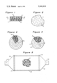
- FIG. 1 of the drawing is a diagrammatic cross-sectional view indicating the formation of a honeycomb type of element through the use of flat sheet-like members and the spacing thereof with round or spherical pieces fused between the spaced sheet members.
- FIG. 2 of the drawing is a plan view of a portion of a honeycomb element, such as indicated by the lines 2--2 in FIG. 1 of the drawing, with the showing of the random positioning of the spherical pieces between the spaced sheet members.
- FIG. 3 of the drawing shows, in a partial sectional view, the use of spacing spherical pieces between spaced apart concentric cylinder-like sheets of ceramic material such that there is a resulting cylinder-form honeycomb element.
- FIG. 4 of the drawing also indicates in a partial sectional view the utilization of randomly spaced round or spherical pieces between the successive layers of a spirally wrapped ceramic sheet material to form a resulting rigid honeycomb element.
- FIG. 5 of the drawing is a diagrammatic elevational view, partially in section, indicating the use of one of the improved types of honeycomb elements within a suitable housing to accommodate a waste gas stream.
- FIGS. 1 and 2 of the drawing there is indicated the utilization of a plurality of spaced apart ceramic sheet members 1 and a multiplicity of round or generally spherical ceramic pieces 2 between each sheet member 1 such that there is a resulting honeycomb or rigid skeletal element which can serve to pass a fluid stream through the layers of sheet-like material 1.
- Any number of sheet members 1 can be utilized to provide a multiplicity of layers and relatively large ceramic elements where such may be desired.
- the size of the balls or spheres 2 which are used to effect the spacing of sheet members 1 can vary but will be of the same size in any one layer and typically be sized so as to provide spacings between sheets of the order of 1/16 inch to 1/2 inch, or more, depending upon the type of conversion to take place and pressure drop considerations. It is not believed necessary to describe the actual method of forming the ceramic materials in view of the teachings set forth in the aforementioned patents.
- the multiplicity of generally spherical members 2 have been placed randomly between the flat sheets 1; however, the balls 2 can be positioned in two-way rows as long as they are staggered and will not permit a straight through fluid flow in any one direction.
- the random positioning of the spheres between the sheets will effect the desired turbulent flow for a stream to be converted in a catalytically activated element.
- the number of spheres utilized in each layer, as well as their size, will effect the amount of turbulence and the resulting pressure drop for a particular converter element.
- FIG. 3 of the drawing there is indicated the utilization of a plurality of balls or spheres 3 of refractory material between a plurality of spaced apart concentric cylinder-like ceramic members indicated at 4, 5, 6, 7 and 8.
- the spacing balls 3 will be fused or otherwise rigidly positioned between the spaced apart cylindrical members so as to form a resulting rigid honeycomb member suitable for use as a catalyst support element.
- the size of the spheres and the spacing between concentric members, as well as a number of concentric members being used, will vary in accordance with the desired size of a finished contacting element.
- FIG. 4 of the drawing there is indicated a formation of a generally round rigid structure formed from the spiral wrapping of a ceramic sheet 9 around a multiplicity of generally round or spherical members 10 such that the latter will effect the spacing for each successive wrapping of sheet 9.
- the spheres 10 will be positioned between layers of helical wrapping 9 in a random manner or in staggered rows that will effect a staggered positioning within each successive winding whereby there will be turbulent flow for a gas stream being introduced through the resulting support element.
- FIG. 5 of the drawing there is indicated diagrammatically the placement of a honeycomb element 11 within a cylindrical-form housing 12 which in turn is provided with conical-form end sections 13 and 14. The latter in turn are provided with the respective inlet and outlet means 15 and 16 such that a gaseous stream may be passed through the housing and through the honeycomb element 11.
- Suitable ring members 17 and 18 which are provided internally at the end portions of cylindrical housing section 12 to preclude longitudinal movement of the element 11.
- a resilient packing around the element 11 and along the interior wall of central housing section 12 in order that the honeycomb element may better withstand gas pulsations and vehicle jarring under harsh driving conditions.
- the element 11 will be such as to provide for an end-to-end gas flow through the converter housing and provide for an efficient contact of all of its internal surfaces with the particular gaseous stream so that there is the desired catalytic conversion of the noxious components of the particular stream.
- the honeycomb configuration may be like any one of those indicated in FIGS. 1, 3 and 4, or may comprise still another configuration resulting from the use of spaced apart sheet-like members and intermediate spacing generally round members between the sheet-like members to permit a tortuous gas passageway therethrough.
- the terms "sheet members” and “sheet-like members” relate to both flat sheets and concentric members, as well as the use of a single sheet in a helical configuration and it is not intended to limit the terms to strictly flat sheet members.
- the resulting skeletal elements or honeycombs of the present invention will, in each instance, provide greater catalytic efficiency because of the increased turbulence and contact between the gaseous stream and the coated surfaces of the ceramic element.
- inorganic refractory oxide pills or spherical members are used in combination with ceramic sheet-like members there can be greater porosity for the spacing spheres such that there is still further increased catalytic activity for the catalytic coated spherical members.
- the present improved element provides for the elimination of the generally laminar flows of typical honeycomb types of elements and a greater efficiency for the conversion of any particular reactant stream.
Landscapes
- Chemical & Material Sciences (AREA)
- Engineering & Computer Science (AREA)
- Chemical Kinetics & Catalysis (AREA)
- Health & Medical Sciences (AREA)
- Toxicology (AREA)
- Combustion & Propulsion (AREA)
- Mechanical Engineering (AREA)
- General Engineering & Computer Science (AREA)
- Ceramic Engineering (AREA)
- Environmental & Geological Engineering (AREA)
- Analytical Chemistry (AREA)
- General Chemical & Material Sciences (AREA)
- Oil, Petroleum & Natural Gas (AREA)
- Biomedical Technology (AREA)
- Materials Engineering (AREA)
- Organic Chemistry (AREA)
- Exhaust Gas After Treatment (AREA)
- Catalysts (AREA)
Abstract
A rigid monolithic catalyst support member is formed by having substantially round pellets of ceramic, or other refractory material, positioned in a staggered or random manner between spaced apart rigid sheetlike members such that there will be a turbulent fluid flow for a stream passing between the layers of such sheet-like members. Typically, the support materials will be of the same type of materials used for making the refractory "honeycomb" members, such as petalite, cordierite, alumina-silicates, alumina-silica-magnesia, zircon-mullite, alpha-alumina, etc.
Description
The present invention relates to a special form of rigid refractory honeycomb or skeletal ceramic type of element which is temperature resistant and sufficiently porous as to provide a support for a catalyst coating.
More particularly, the present support element is formed by integrating uniformly sized spheres, or substantially round pellets, between spaced layers of sheet-like members such that the resulting support element will provide a tortuous turbulent flow path for a fluid stream passing between the layers of the element.
The present special form of refractory member is also of particular value in providing a rigid catalyst support member for use in automobile catalytic converters to treat auto exhaust gases.
Catalytic materials for chemical and petroleum processing, as well as for auto exhaust gas converters, have been prepared in many forms, including powders, balls, small spheres, micor-spheres, shaped pellets, etc., and also have been used in various types of arrangements including: single beds, spaced beds, annular beds, suspensions, and the like. Small spheres in the 1/16 inch to 1/4 inch range are widely used since they are readily prepared commercially to have high surface area, low bulk density and can be coated to have high activity. However, in conducting field testing of automobile exhaust gas catalytic converters, it has been observed that many converters "fail" from catalyst losses due to catalyst breakage and/or attrition. The breakage and attrition or abrasion of particles is generally due to the loosening of the catalyst particles in the bed and the resulting relatively free movement of individual particles. The looseness may result from catalyst breakage caused by expansion and contraction movements of a metal converter housing as well as from warpage of perforated plates or screens which are used to retain the catalyst in the housing. With some catalysts, there also may be some initial shrinkage of the finished catalyst after being subjected to high temperature operating conditions. It has also been found that most of the catalyst movement in a converter bed, after some looseness does occur, is primarily due to the pulsating engine exhaust gas stream although some movement is, of course, due to engine vibrations and road roughness.
In order to overcome the problem of catalyst pill and pellet breakage problems, there have been experimental and commercial usage of rigid honeycomb and skeletal types of elements. As examples, reference may be made to U.S. Pat. Nos. 3,344,925 and 3,505,030. The latter patent, in turn, provides a summary description of various shapes and various methods of manufacturing the skeletal elements, as well as set forth still other U.S. and foreign patents which disclose methods of preparing honeycomb type ceramic elements. From these patents, as well as from other descriptive material, it will be noted that each skeletal member or element has a multiplicity of straight-through, parallel channels whether having openings from an extrusion operation or passageways formed from the use of corrugated layers. As a result, there is laminar flow for a reactant stream and a loss of conversion efficiency due to the inadequate contact between the catalytically coated surfaces of the channels and the stream to be converted. Conversely, a converter utilizing a bed of catalyst pills or pellets will provide turbulence and a highly efficient contact between the reactant stream and the catalyst surfaces. The need of a thick catalyst bed of spheres or pellets can, of course, with certain streams, present an undesirable aspect of causing an excessive pressure drop through the bed.
In any event, it may be considered a principal object of the present invention to provide an improved form of ceramic type converter element which will have structural rigidity and, at the same time, obviate the problem of the straight-through, unidirectional, parallel channels.
As another object of the invention, there is provided the benefit of staggered or randomly placed pills in combination with spaced apart sheet members to form rigid ceramic catalyst support elements such that greater turbulence and surface contact efficiency can take place.
In a broad embodiment, the present invention provides a monolithic catalyst support member which comprises in combination, a plurality of spaced apart rigid ceramic sheet members and a multiplicity of substantially round pellets of rigid refractory material affixed to and, in turn, spaced apart between said spaced sheet members, with such round pellets being positioned in a manner other than in non-staggered rows to thereby provide turbulent fluid flow for a stream passing between the sheet members.
In another embodiment, the present invention provides a catalytic converter for effecting the conversion of a waste gas stream, which comprises in combination: (a) a housing with gas inlet means to one end thereof and a gas outlet means from the other end thereof, and (b) at least one rigid refractory honeycomb type of ceramic element with a conversion catalyst coating thereon positioned within said housing to provide for turbulent gas flow therethrough from said gas inlet means to said gas outlet means, with (c) said ceramic element formed of spaced apart sheet members and a multiplicity of substantially round members of rigid refractory material affixed to and, in turn, spaced apart between said spaced sheet members in a manner other than in non-staggered rows, whereby there is a desired resulting turbulent flow for the gas stream passing between the sheet members.
It is not intended to limit the invention to the use of any one particular type of ceramic material or to any one shape for the resulting honeycomb cross section. There are various compositions for the honeycomb or skeletal structural support materials and such structures may comprise alpha-alumina, alumina-silica-magnesia, zirconia-silicate, zircon-mullite, and the like. Actually, other refractory crystalline ceramic materials which may be formed into honeycombs or rigid skeletal structures and which are utilizable may comprise sillimanite, zircon, petalite, spondumene, cordierite, and alumina-silicates. Various of the skeletal ceramic materials are presently on the market, as for example, ThermaComb corrugated ceramics made by the American Lava Corporation, a subsidiary of 3M Corporation. Also, the E. I. DuPont, Inc. organization provides commercial types of honeycomb elements. The aforementioned U.S. Pat. Nos. 3,344,925 and 3,505,030 describe various types of materials and methods of making honeycomb structures such that reference may be made to these patents for more detailed descriptions of methods of preparation, as well as composition.
Typically, the present improved ceramic honeycomb elements will have both the sheet members and the round pills or spheres provided of the same type of composition, with the same general characteristics of coefficient of expansion, etc., such that the spacing pills will become fused with the sheet-like members and provide a rigid structure. However, the randomly spaced spherical pieces placed between the spaced apart sheet members may be of a hard refractory material other than a ceramic, as long as there is the capability to become fused and fixedly held between the sheet members and not have a greatly different coefficient of expansion. For example, relatively hard catalyst support spheres made from alumina, silica, silica-alumina, alumina-magnesia, etc., or other inorganic oxides, may well be utilized, particularly, catalyst support pills which are of relatively high bulk density or have been hardened or stabilized with additive materials such as barium or other alkaline earth components.
Typically, the honeycomb element may be formed by utilizing a plurality of spaced apart flat sheet members of ceramic material along with the utilization of staggeredly positioned or randomly placed spheres between sheet members such that there is a desired resulting turbulent flow for any fluid stream passing through the element. On the other hand, the element may be formed from a plurality of concentric ceramic members spaced apart by the multiplicity of spheres or round pellet members of additional ceramic material or of the hardened refractory inorganic oxide materials such that again there is the resulting turbulence for any fluid stream that will pass through the concentric members of the element. In still another arrangement, there can be the spiral winding of one or more sheets of ceramic material with each winding being around a multiplicity of pills or spherical ceramic pieces such that there is spacing between windings in the resulting element and a resulting turbulent fluid flow for a stream that will pass through the helical element and around the multiplicity of spacing spherical members.
When using the resulting element in a reactor or catalytic converter, there will, of course, be a suitable catalytic coating applied to the structural support element prior to its being placed in the particular reactor or converter chamber. The catalytic coating, where the element is to be used in an oxidation reaction, may include metals of Group IIA, IB, VB, VIB, VIIB and VIII and particularly copper, silica, vanadium, chromium, iron, cobalt, nickel, platinum, palladium, rhodium, ruthenium, etc., with the components being used singly or in combination with one or more other active component. The present type of honeycomb support member may also be utilized to carry out reduction operations, as for example, in effecting the reduction of nitrogen oxides in vehicular exhaust gas streams to form the less noxious components of nitrogen and carbon dioxide. Thus, the catalyst coating on the support member may well provide a reducing activity and comprise copper oxide, or copper oxide-cobalt oxide. Other catalytic reducing components may be one or more metals or metal oxides from the iron group of metals, or of Group VII, of the Periodic Table. Actually, in connection with the conversion of engine exhaust gas streams, it may be of advantage to use more than one contact bed in a multiple stage operation, with an active reducing coating on the support element in a first stage and an active oxidation catalytic coating on the support element on a second stage, with air being introduced between the two stages to provide for better oxidizing position in the latter stage.
Reference to the accompanying drawing and the following description thereof will serve to illustrate the present invention as well as set forth additional advantages which may be obtained in connection with the use of this type of construction and arrangement.
FIG. 1 of the drawing is a diagrammatic cross-sectional view indicating the formation of a honeycomb type of element through the use of flat sheet-like members and the spacing thereof with round or spherical pieces fused between the spaced sheet members.
FIG. 2 of the drawing is a plan view of a portion of a honeycomb element, such as indicated by the lines 2--2 in FIG. 1 of the drawing, with the showing of the random positioning of the spherical pieces between the spaced sheet members.
FIG. 3 of the drawing shows, in a partial sectional view, the use of spacing spherical pieces between spaced apart concentric cylinder-like sheets of ceramic material such that there is a resulting cylinder-form honeycomb element.
FIG. 4 of the drawing also indicates in a partial sectional view the utilization of randomly spaced round or spherical pieces between the successive layers of a spirally wrapped ceramic sheet material to form a resulting rigid honeycomb element.
FIG. 5 of the drawing is a diagrammatic elevational view, partially in section, indicating the use of one of the improved types of honeycomb elements within a suitable housing to accommodate a waste gas stream.
Referring now particularly to FIGS. 1 and 2 of the drawing, there is indicated the utilization of a plurality of spaced apart ceramic sheet members 1 and a multiplicity of round or generally spherical ceramic pieces 2 between each sheet member 1 such that there is a resulting honeycomb or rigid skeletal element which can serve to pass a fluid stream through the layers of sheet-like material 1. Any number of sheet members 1 can be utilized to provide a multiplicity of layers and relatively large ceramic elements where such may be desired. The size of the balls or spheres 2 which are used to effect the spacing of sheet members 1 can vary but will be of the same size in any one layer and typically be sized so as to provide spacings between sheets of the order of 1/16 inch to 1/2 inch, or more, depending upon the type of conversion to take place and pressure drop considerations. It is not believed necessary to describe the actual method of forming the ceramic materials in view of the teachings set forth in the aforementioned patents.
In FIG. 2 of the drawing it will be noted that the multiplicity of generally spherical members 2 have been placed randomly between the flat sheets 1; however, the balls 2 can be positioned in two-way rows as long as they are staggered and will not permit a straight through fluid flow in any one direction. Typically the random positioning of the spheres between the sheets will effect the desired turbulent flow for a stream to be converted in a catalytically activated element. As will be obvious, the number of spheres utilized in each layer, as well as their size, will effect the amount of turbulence and the resulting pressure drop for a particular converter element.
In FIG. 3 of the drawing, there is indicated the utilization of a plurality of balls or spheres 3 of refractory material between a plurality of spaced apart concentric cylinder-like ceramic members indicated at 4, 5, 6, 7 and 8. Here again, the spacing balls 3 will be fused or otherwise rigidly positioned between the spaced apart cylindrical members so as to form a resulting rigid honeycomb member suitable for use as a catalyst support element. The size of the spheres and the spacing between concentric members, as well as a number of concentric members being used, will vary in accordance with the desired size of a finished contacting element.
In FIG. 4 of the drawing there is indicated a formation of a generally round rigid structure formed from the spiral wrapping of a ceramic sheet 9 around a multiplicity of generally round or spherical members 10 such that the latter will effect the spacing for each successive wrapping of sheet 9. Again, the spheres 10 will be positioned between layers of helical wrapping 9 in a random manner or in staggered rows that will effect a staggered positioning within each successive winding whereby there will be turbulent flow for a gas stream being introduced through the resulting support element.
In FIG. 5 of the drawing, there is indicated diagrammatically the placement of a honeycomb element 11 within a cylindrical-form housing 12 which in turn is provided with conical-form end sections 13 and 14. The latter in turn are provided with the respective inlet and outlet means 15 and 16 such that a gaseous stream may be passed through the housing and through the honeycomb element 11.
Various methods of holding the element 11 within the central housing portion 12 at the converter unit may be utilized, as for example by suitable ring members 17 and 18 which are provided internally at the end portions of cylindrical housing section 12 to preclude longitudinal movement of the element 11. Also, where desired, there may be utilized a resilient packing around the element 11 and along the interior wall of central housing section 12 in order that the honeycomb element may better withstand gas pulsations and vehicle jarring under harsh driving conditions. The element 11 will be such as to provide for an end-to-end gas flow through the converter housing and provide for an efficient contact of all of its internal surfaces with the particular gaseous stream so that there is the desired catalytic conversion of the noxious components of the particular stream. The honeycomb configuration may be like any one of those indicated in FIGS. 1, 3 and 4, or may comprise still another configuration resulting from the use of spaced apart sheet-like members and intermediate spacing generally round members between the sheet-like members to permit a tortuous gas passageway therethrough.
It should be noted in the present application that the terms "sheet members" and "sheet-like members" relate to both flat sheets and concentric members, as well as the use of a single sheet in a helical configuration and it is not intended to limit the terms to strictly flat sheet members. The resulting skeletal elements or honeycombs of the present invention will, in each instance, provide greater catalytic efficiency because of the increased turbulence and contact between the gaseous stream and the coated surfaces of the ceramic element. Also, where inorganic refractory oxide pills or spherical members are used in combination with ceramic sheet-like members there can be greater porosity for the spacing spheres such that there is still further increased catalytic activity for the catalytic coated spherical members. In any event, the present improved element provides for the elimination of the generally laminar flows of typical honeycomb types of elements and a greater efficiency for the conversion of any particular reactant stream.
Claims (7)
1. A rigid and monolithic catalyst support member which comprises in combination, a plurality of spaced-apart, rigid ceramic sheet members and a multiplicity of substantially round pellets of rigid refractory material positioned in a layer in a spaced-apart manner between said sheet members in which said refractory material is fused to said spaced ceramic sheet members, with said round pellets being staggeredly positioned in said layer to thereby provide turbulent fluid flow for a stream passing between said sheet members.
2. The catalyst support member of claim 1 further characterized in that said spaced sheet members are generally flat.
3. The catalyst support member of claim 1 further characterized in that said spaced sheet members are of a plurality of concentric cylinder-like members.
4. The catalyst support member of claim 1 further characterized in that said spaced sheet members result from the spiral winding of at least one sheet-like member.
5. The catalyst support member of claim 1 further characterized in that said substantially round pellets are of a ceramic material similar to the composition of that of said ceramic sheet members.
6. The catalyst support member of claim 1 further characterized in that said substantially round pellets are of a refractory inorganic oxide material.
7. The catalyst support member of claim 1 further characterized in that said member is provided with an active oxidation catalyst coating suitable for the conversion of an engine exhaust gas stream.
Priority Applications (1)
| Application Number | Priority Date | Filing Date | Title |
|---|---|---|---|
| US05/491,007 US3948810A (en) | 1974-07-23 | 1974-07-23 | Monolithic catalyst support member |
Applications Claiming Priority (1)
| Application Number | Priority Date | Filing Date | Title |
|---|---|---|---|
| US05/491,007 US3948810A (en) | 1974-07-23 | 1974-07-23 | Monolithic catalyst support member |
Publications (1)
| Publication Number | Publication Date |
|---|---|
| US3948810A true US3948810A (en) | 1976-04-06 |
Family
ID=23950430
Family Applications (1)
| Application Number | Title | Priority Date | Filing Date |
|---|---|---|---|
| US05/491,007 Expired - Lifetime US3948810A (en) | 1974-07-23 | 1974-07-23 | Monolithic catalyst support member |
Country Status (1)
| Country | Link |
|---|---|
| US (1) | US3948810A (en) |
Cited By (23)
| Publication number | Priority date | Publication date | Assignee | Title |
|---|---|---|---|---|
| US4289855A (en) * | 1977-12-30 | 1981-09-15 | Oxoid Limited | Safety catalyst systems |
| US4631269A (en) * | 1985-03-18 | 1986-12-23 | Corning Glass Works | Monolithic catalyst supports incorporating a mixture of alumina and silica as a high surface area catalyst support material |
| EP0247292A1 (en) * | 1986-05-17 | 1987-12-02 | Didier-Werke Ag | N0x-eliminating unit |
| EP0304762A1 (en) * | 1987-08-26 | 1989-03-01 | W.R. Grace & Co.-Conn. | Particulate trap |
| FR2625257A1 (en) * | 1987-12-24 | 1989-06-30 | Sotralentz Sa | DEVICE FOR THE CATALYTIC TREATMENT OF COMBUSTION GASES OF AN AUTOMOTIVE ENGINE AND METHOD FOR MANUFACTURING A CATALYST CARTRIDGE FOR SUCH A DEVICE |
| US5099085A (en) * | 1988-11-17 | 1992-03-24 | Wacker Chemie Gmbh | Chlorination reactions and oxychlorination reactions in the presence of honeycomb monolithic catalyst supports |
| US5173349A (en) * | 1989-07-28 | 1992-12-22 | Engelhard Corporation | Thermal shock and creep resistant mullite articles prepared from topaz and process of manufacture |
| WO1996027441A1 (en) * | 1995-03-06 | 1996-09-12 | Siemens Aktiengesellschaft | Plate-shaped catalyser unit |
| US5732555A (en) * | 1994-10-19 | 1998-03-31 | Briggs & Stratton Corporation | Multi-pass catalytic converter |
| US5786296A (en) * | 1994-11-09 | 1998-07-28 | American Scientific Materials Technologies L.P. | Thin-walled, monolithic iron oxide structures made from steels |
| US6051203A (en) * | 1996-04-30 | 2000-04-18 | American Scientific Materials Technologies, L.P. | Thin-walled monolithic metal oxide structures made from metals, and methods for manufacturing such structures |
| EP1088969A2 (en) * | 1999-10-01 | 2001-04-04 | Ford Global Technologies, Inc. | A catalyst assembly for an exhaust gas system |
| US6461562B1 (en) | 1999-02-17 | 2002-10-08 | American Scientific Materials Technologies, Lp | Methods of making sintered metal oxide articles |
| US20030003030A1 (en) * | 2001-06-27 | 2003-01-02 | Glenn Knight | Reverse flow catalytic muffler |
| EP1108865A3 (en) * | 1999-12-13 | 2003-07-09 | Ford Global Technologies, Inc. | Catalyst construction for treating lean burn engine exhaust |
| EP1108864A3 (en) * | 1999-12-13 | 2003-07-16 | Ford Global Technologies, Inc. | Noise attenuating emission converter |
| US6622482B2 (en) | 2001-06-27 | 2003-09-23 | Environmental Control Corporation | Combined catalytic muffler |
| US6756016B2 (en) * | 1999-01-25 | 2004-06-29 | Mine Safety Appliances Company | Gas sensor |
| US6790417B2 (en) | 2000-12-21 | 2004-09-14 | Corning Incorporated | Monolith loop reactors |
| US10234412B2 (en) | 2016-11-04 | 2019-03-19 | Msa Technology, Llc | Identification of combustible gas species via pulsed operation of a combustible gas sensor |
| US10598068B2 (en) | 2015-12-21 | 2020-03-24 | Emissol, Llc | Catalytic converters having non-linear flow channels |
| US10900922B2 (en) | 2018-07-17 | 2021-01-26 | Msa Technology, Llc | Power reduction in combustible gas sensors |
| US11703473B2 (en) | 2019-12-11 | 2023-07-18 | Msa Technology, Llc | Operation of combustible gas sensor in a dynamic mode with a constant resistance setpoint |
Citations (2)
| Publication number | Priority date | Publication date | Assignee | Title |
|---|---|---|---|---|
| US3528783A (en) * | 1964-06-16 | 1970-09-15 | Marston Excelsior Ltd | Multilayer catalytic reactor |
| US3785781A (en) * | 1971-10-04 | 1974-01-15 | Universal Oil Prod Co | Apparatus for catalytically converting fluid |
-
1974
- 1974-07-23 US US05/491,007 patent/US3948810A/en not_active Expired - Lifetime
Patent Citations (2)
| Publication number | Priority date | Publication date | Assignee | Title |
|---|---|---|---|---|
| US3528783A (en) * | 1964-06-16 | 1970-09-15 | Marston Excelsior Ltd | Multilayer catalytic reactor |
| US3785781A (en) * | 1971-10-04 | 1974-01-15 | Universal Oil Prod Co | Apparatus for catalytically converting fluid |
Cited By (31)
| Publication number | Priority date | Publication date | Assignee | Title |
|---|---|---|---|---|
| US4289855A (en) * | 1977-12-30 | 1981-09-15 | Oxoid Limited | Safety catalyst systems |
| US4631269A (en) * | 1985-03-18 | 1986-12-23 | Corning Glass Works | Monolithic catalyst supports incorporating a mixture of alumina and silica as a high surface area catalyst support material |
| EP0247292A1 (en) * | 1986-05-17 | 1987-12-02 | Didier-Werke Ag | N0x-eliminating unit |
| EP0304762A1 (en) * | 1987-08-26 | 1989-03-01 | W.R. Grace & Co.-Conn. | Particulate trap |
| FR2625257A1 (en) * | 1987-12-24 | 1989-06-30 | Sotralentz Sa | DEVICE FOR THE CATALYTIC TREATMENT OF COMBUSTION GASES OF AN AUTOMOTIVE ENGINE AND METHOD FOR MANUFACTURING A CATALYST CARTRIDGE FOR SUCH A DEVICE |
| US5099085A (en) * | 1988-11-17 | 1992-03-24 | Wacker Chemie Gmbh | Chlorination reactions and oxychlorination reactions in the presence of honeycomb monolithic catalyst supports |
| US5173349A (en) * | 1989-07-28 | 1992-12-22 | Engelhard Corporation | Thermal shock and creep resistant mullite articles prepared from topaz and process of manufacture |
| US5732555A (en) * | 1994-10-19 | 1998-03-31 | Briggs & Stratton Corporation | Multi-pass catalytic converter |
| US5786296A (en) * | 1994-11-09 | 1998-07-28 | American Scientific Materials Technologies L.P. | Thin-walled, monolithic iron oxide structures made from steels |
| US5814164A (en) * | 1994-11-09 | 1998-09-29 | American Scientific Materials Technologies L.P. | Thin-walled, monolithic iron oxide structures made from steels, and methods for manufacturing such structures |
| WO1996027441A1 (en) * | 1995-03-06 | 1996-09-12 | Siemens Aktiengesellschaft | Plate-shaped catalyser unit |
| US6051203A (en) * | 1996-04-30 | 2000-04-18 | American Scientific Materials Technologies, L.P. | Thin-walled monolithic metal oxide structures made from metals, and methods for manufacturing such structures |
| US6071590A (en) * | 1996-04-30 | 2000-06-06 | American Scientific Materials Technologies, L.P. | Thin-walled monolithic metal oxide structures made from metals, and methods for manufacturing such structures |
| US6077370A (en) * | 1996-04-30 | 2000-06-20 | American Scientific Materials Technologies, L.P. | Thin-walled monolithic metal oxide structures made from metals, and methods for manufacturing such structures |
| US6756016B2 (en) * | 1999-01-25 | 2004-06-29 | Mine Safety Appliances Company | Gas sensor |
| US6461562B1 (en) | 1999-02-17 | 2002-10-08 | American Scientific Materials Technologies, Lp | Methods of making sintered metal oxide articles |
| EP1088969A2 (en) * | 1999-10-01 | 2001-04-04 | Ford Global Technologies, Inc. | A catalyst assembly for an exhaust gas system |
| EP1088969A3 (en) * | 1999-10-04 | 2003-06-11 | Ford Global Technologies, Inc. | A catalyst assembly for an exhaust gas system |
| EP1108865A3 (en) * | 1999-12-13 | 2003-07-09 | Ford Global Technologies, Inc. | Catalyst construction for treating lean burn engine exhaust |
| EP1108864A3 (en) * | 1999-12-13 | 2003-07-16 | Ford Global Technologies, Inc. | Noise attenuating emission converter |
| US20030211020A1 (en) * | 1999-12-13 | 2003-11-13 | Rao V. Durga Nageswar | Noise attenuating emission converter |
| US6790417B2 (en) | 2000-12-21 | 2004-09-14 | Corning Incorporated | Monolith loop reactors |
| US6622482B2 (en) | 2001-06-27 | 2003-09-23 | Environmental Control Corporation | Combined catalytic muffler |
| US20030003030A1 (en) * | 2001-06-27 | 2003-01-02 | Glenn Knight | Reverse flow catalytic muffler |
| US7018590B2 (en) | 2001-06-27 | 2006-03-28 | Environmental Control Corporation | Reverse flow catalytic muffler |
| US10598068B2 (en) | 2015-12-21 | 2020-03-24 | Emissol, Llc | Catalytic converters having non-linear flow channels |
| US10815856B2 (en) | 2015-12-21 | 2020-10-27 | Mansour Masoudi | Catalytic converters having non-linear flow channels |
| US10234412B2 (en) | 2016-11-04 | 2019-03-19 | Msa Technology, Llc | Identification of combustible gas species via pulsed operation of a combustible gas sensor |
| US10705041B2 (en) | 2016-11-04 | 2020-07-07 | Msa Technology, Llc | Identification of combustible gas species via pulsed operation of a combustible gas sensor |
| US10900922B2 (en) | 2018-07-17 | 2021-01-26 | Msa Technology, Llc | Power reduction in combustible gas sensors |
| US11703473B2 (en) | 2019-12-11 | 2023-07-18 | Msa Technology, Llc | Operation of combustible gas sensor in a dynamic mode with a constant resistance setpoint |
Similar Documents
| Publication | Publication Date | Title |
|---|---|---|
| US3948810A (en) | Monolithic catalyst support member | |
| US3903341A (en) | Ceramic honeycomb structure for accommodating compression and tension forces | |
| US3692497A (en) | Catalytic exhaust gas treatment apparatus | |
| US4388277A (en) | Catalyst device and method | |
| JP4241933B2 (en) | Heat resistant regenerative filter body with flow path | |
| US3948611A (en) | Catalytic converter having hollow, gas-filled mounting means for a monolithic catalyst | |
| US3441381A (en) | Apparatus for purifying exhaust gases of an internal combustion engine | |
| US6159578A (en) | Hexagonal-cell honeycomb structure and method for fixation thereof | |
| CA1127973A (en) | Catalytic apparatus | |
| US3785781A (en) | Apparatus for catalytically converting fluid | |
| Cybulski et al. | Monoliths in heterogeneous catalysis | |
| US4385032A (en) | Catalytic waste gas converter for combustion machines | |
| US3754870A (en) | Method and means of catalytically converting fluids | |
| US7083860B2 (en) | Metallic honeycomb body having at least partially perforated sheet-metal layers | |
| US5009857A (en) | Filter for gases | |
| US4388275A (en) | Apparatus containing a carrier matrix for catalysts | |
| KR20020047154A (en) | Catalyst for the selective oxidation of carbon monoxide and its preparation | |
| JPH0812460A (en) | Honeycomb ceramic structure | |
| CA1137876A (en) | Catalyst supports | |
| AU761031B2 (en) | Exhaust emission control catalyst structure and device | |
| US5474745A (en) | Catalytic converter for purifying exhaust gas | |
| US11179675B2 (en) | Reactor for reducing nitrogen oxides | |
| US4078898A (en) | Catalyst-coated expanded metal foil substrate for an exhaust gas reactor | |
| JPH10244167A (en) | Catalyst structure body for purifying exhaust gas | |
| JPS62266298A (en) | Ceramic honeycomb structure |
Legal Events
| Date | Code | Title | Description |
|---|---|---|---|
| AS | Assignment |
Owner name: UOP, DES PLAINES, IL, A NY GENERAL PARTNERSHIP Free format text: ASSIGNMENT OF ASSIGNORS INTEREST.;ASSIGNOR:KATALISTIKS INTERNATIONAL, INC., A CORP. OF MD;REEL/FRAME:005006/0782 Effective date: 19880916 |
|
| AS | Assignment |
Owner name: UOP, A GENERAL PARTNERSHIP OF NY, ILLINOIS Free format text: ASSIGNMENT OF ASSIGNORS INTEREST.;ASSIGNOR:UOP INC.;REEL/FRAME:005077/0005 Effective date: 19880822 |