US3980277A - Device for fence consisting of a number of posts with electrically conducting conductors and a high tension unit - Google Patents
Device for fence consisting of a number of posts with electrically conducting conductors and a high tension unit Download PDFInfo
- Publication number
- US3980277A US3980277A US05/516,666 US51666674A US3980277A US 3980277 A US3980277 A US 3980277A US 51666674 A US51666674 A US 51666674A US 3980277 A US3980277 A US 3980277A
- Authority
- US
- United States
- Prior art keywords
- posts
- strip
- fence
- layers
- post
- Prior art date
- Legal status (The legal status is an assumption and is not a legal conclusion. Google has not performed a legal analysis and makes no representation as to the accuracy of the status listed.)
- Expired - Lifetime
Links
Images
Classifications
-
- A—HUMAN NECESSITIES
- A01—AGRICULTURE; FORESTRY; ANIMAL HUSBANDRY; HUNTING; TRAPPING; FISHING
- A01K—ANIMAL HUSBANDRY; CARE OF BIRDS, FISHES, INSECTS; FISHING; REARING OR BREEDING ANIMALS, NOT OTHERWISE PROVIDED FOR; NEW BREEDS OF ANIMALS
- A01K3/00—Pasturing equipment, e.g. tethering devices; Grids for preventing cattle from straying; Electrified wire fencing
- A01K3/005—Electrified fencing for pastures
-
- H—ELECTRICITY
- H05—ELECTRIC TECHNIQUES NOT OTHERWISE PROVIDED FOR
- H05C—ELECTRIC CIRCUITS OR APPARATUS SPECIALLY DESIGNED FOR USE IN EQUIPMENT FOR KILLING, STUNNING, OR GUIDING LIVING BEINGS
- H05C1/00—Circuits or apparatus for generating electric shock effects
Definitions
- the present invention relates to a device for a fence, particularly for enclosing animals or for preventing the passage of animals, consisting of a number of posts connected together with each other with one or several electric conductors connected to a high voltage unit, so that animals coming into contact with the wire receive an electric shock.
- Fences of this kind have been known for a long time.
- the wires between the individual posts are usually metal wires with a circular cross-section. Said wires are charged in relation to ground by a high tension unit.
- a fence has the drawback that it is difficult for the animals to discern, and the animals can therefore run against the fence so that it will break.
- the purpose of the present invention is to provide a fence which is easily observed by animals, and which does not easily become grounded by vegetation growing up near it.
- the fence consists of a metal strip, the flat surfaces of which are coated with an electrically insulating layer, so that only the edge surfaces of the flat surfaces will be uncoated.
- the insulating layers are moreover chosen in such a way that the strength of the metal strip is increased in relation to that of the metal strip without the coating.
- the metal strip is appropriately of aluminum, and the layers usually consist of plastics material of the same or of different kinds.
- Conceivable plastics are polyester, polyethylene and polyvinyl chloride.
- the metal strip between two posts is usually turned or twisted around its longitudinal axis, so that the edge surfaces of the strip have a more or less screw-like form, in order to ensure that contact is made with the body of an animal.
- the coatings on the metal strips can have different colors, depending on what kinds of animals are to be enclosed.
- the color can either be frightening, so that an animal, on seeing the strip turns away from it, or else the color can be such that the animal will be curious about the strip, and because of its curiousness it receives an electric shock, and in that way learns that it cannot go too near the metal strip.
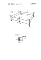
- FIG. 1 shows a fence according to the present invention
- FIG. 2 shows a metal strip comprised in the fence according to FIG. 1.
- the reference designations 1, 2, 3, 4 and 5 refer to posts anchored in the ground, of which the post 5 contains a high voltage unit provided with connection wires 8 and 9 to the fence conductors 6 and 7.
- Each of the fence conductors consist of a flat pliable metal strip or ribbon 10, appropriately of aluminum.
- An appropriate thickness of the metal strip is 12 ⁇ m.
- the upper and lower sides of the strip are coated with pliable plastic layers 11 and 12, which can have varying thicknesses up to 200 ⁇ m. Thicknesses of 50 and 100 ⁇ m can also be used.
- Said plastic layer can consist of a polyester, of polyethylene or of polyvinyl chloride. The thickness of the plastic layers is determined by the tensile stresses to which the strip may be subjected.
- the two plastic layers 11 and 12 have the same width as the strip 10, so that the strip 10 is unprotected electrically only at the two edge surfaces.
- the two layers can be of the same or of different plastic.
- the five posts 1-5 are anchored, after which the electric conductors 6 and 7 are fastened to the posts.
- the fastening device at the post 5 appropriately consists of an eyebolt.
- One end of the strip is appropriately pulled through the eye, so that the strip itself at the fastening point forms an eye.
- a tubular or sleeve-like plastic part is placed, which keeps the end of the strip secured to the post 5. Thereafter the strip is turned around its longitudinal axis, so that it becomes twisted.
- the strip is fastened to the nearest adjacent post, for instance by allowing the strip to form an eye which is laid around the post 5 allowing a tubular part of the previously mentioned kind through which two parts of the strip pass and from where the eye originates to determine the size of the eye. Between said two posts, the strip thus has the character of a screwed line. The same procedure is applied for the connection to the other posts and, finally, the other end of the strip is fastened to the post 5 with the high voltage unit. The strip is thus twisted between all of the posts.
- the strip Due to the fact that the strip is twisted, it is adequately ensured that the body of an animal which touches the fence will obtain a conducting contact with the uninsulated surfaces, and due to the fact that the metal strip can be coated with different colours, the animal will either become afraid of the strip or have its curiosity aroused.
- the fence need not form an enclosure, but can also be arranged to form a barrier, particularly for wild animals.
Abstract
Description
Claims (4)
Priority Applications (1)
| Application Number | Priority Date | Filing Date | Title |
|---|---|---|---|
| US05/516,666 US3980277A (en) | 1972-04-14 | 1974-10-21 | Device for fence consisting of a number of posts with electrically conducting conductors and a high tension unit |
Applications Claiming Priority (4)
| Application Number | Priority Date | Filing Date | Title |
|---|---|---|---|
| SE7204863A SE370486B (en) | 1972-04-14 | 1972-04-14 | |
| SW4863/72 | 1972-04-14 | ||
| US34348173A | 1973-03-21 | 1973-03-21 | |
| US05/516,666 US3980277A (en) | 1972-04-14 | 1974-10-21 | Device for fence consisting of a number of posts with electrically conducting conductors and a high tension unit |
Related Parent Applications (1)
| Application Number | Title | Priority Date | Filing Date |
|---|---|---|---|
| US34348173A Continuation | 1972-04-14 | 1973-03-21 |
Publications (1)
| Publication Number | Publication Date |
|---|---|
| US3980277A true US3980277A (en) | 1976-09-14 |
Family
ID=27354370
Family Applications (1)
| Application Number | Title | Priority Date | Filing Date |
|---|---|---|---|
| US05/516,666 Expired - Lifetime US3980277A (en) | 1972-04-14 | 1974-10-21 | Device for fence consisting of a number of posts with electrically conducting conductors and a high tension unit |
Country Status (1)
| Country | Link |
|---|---|
| US (1) | US3980277A (en) |
Cited By (16)
| Publication number | Priority date | Publication date | Assignee | Title |
|---|---|---|---|---|
| US4111400A (en) * | 1975-04-30 | 1978-09-05 | Nitro Nobel Ab | Electrified fence |
| US4579317A (en) * | 1982-02-18 | 1986-04-01 | Siemens Aktiengesellschaft | Electrode arrangement for capacitive guard fences |
| US4728080A (en) * | 1983-09-13 | 1988-03-01 | Bay Mills Limited | Electric fence wire construction |
| US4755633A (en) * | 1985-10-29 | 1988-07-05 | Standing Colin A | Fencewire having an electrically conductive sheathing |
| US4819914A (en) * | 1985-07-05 | 1989-04-11 | All Line, Inc. | Electrical fence for livestock |
| US4905969A (en) * | 1983-09-13 | 1990-03-06 | Bay Mills Limited | Electric fence wire construction |
| US4973029A (en) * | 1989-10-03 | 1990-11-27 | Robbins Edward S Iii | Conductive wires for fencing systems |
| US5203542A (en) * | 1991-02-26 | 1993-04-20 | Delaware Capital Formation, Inc. | Apparatus for an improved electric fence wire construction for use with intensive grazing |
| US6341550B1 (en) | 1996-11-04 | 2002-01-29 | Eric White | Electrobraid fence |
| US6472602B1 (en) | 2000-07-18 | 2002-10-29 | Gary Pokrandt | Electric fence line and method of weaving |
| US6533881B1 (en) * | 1999-06-18 | 2003-03-18 | John Ronan Wall | Composite metal and plastic fencing and method therefor |
| US6710253B2 (en) * | 2000-07-27 | 2004-03-23 | Lankhorst Indutech B.V. | Electric fence tape, rope or wire and filament therefor |
| US20140150330A1 (en) * | 2012-12-05 | 2014-06-05 | Bird-B-Gone, Inc. | Electrified Deterrent Device Having Insulative Layer |
| US20140311013A1 (en) * | 2012-12-05 | 2014-10-23 | Bird-B-Gone, Inc. | Electrified Deterrent Device Having Insulative Layer |
| US9284746B2 (en) | 2013-11-25 | 2016-03-15 | Edward S. Roberts, III | Insulated fence tensioner |
| USD1006260S1 (en) * | 2021-09-27 | 2023-11-28 | Guangzhou Mibo Zhilian Technology Co. Ltd | Metal rod |
Citations (9)
| Publication number | Priority date | Publication date | Assignee | Title |
|---|---|---|---|---|
| US348008A (en) * | 1886-08-24 | haeeis | ||
| US453326A (en) * | 1891-06-02 | Insulating-cover for trolley or conducting wires for electric railways | ||
| US1136384A (en) * | 1914-03-18 | 1915-04-20 | Arnold B Heine | Tubular conductor for incandescent electric lamps. |
| US2267455A (en) * | 1938-08-02 | 1941-12-23 | Telefunken Gmbh | Flexible radio frequency transmission line |
| US3223796A (en) * | 1962-07-23 | 1965-12-14 | Willoughby Mfg Company | Insulated electric fence wire structure |
| US3286018A (en) * | 1964-12-24 | 1966-11-15 | Gen Electric | Power cable conductor for reducing windage |
| US3366854A (en) * | 1965-04-21 | 1968-01-30 | Charles A Cowsert | Pest repelling apparatus and methods |
| US3413405A (en) * | 1966-10-10 | 1968-11-26 | Stauffer Chemical Co | Electrical shielding tape |
| JPS4418263Y1 (en) * | 1965-03-27 | 1969-08-07 |
-
1974
- 1974-10-21 US US05/516,666 patent/US3980277A/en not_active Expired - Lifetime
Patent Citations (9)
| Publication number | Priority date | Publication date | Assignee | Title |
|---|---|---|---|---|
| US348008A (en) * | 1886-08-24 | haeeis | ||
| US453326A (en) * | 1891-06-02 | Insulating-cover for trolley or conducting wires for electric railways | ||
| US1136384A (en) * | 1914-03-18 | 1915-04-20 | Arnold B Heine | Tubular conductor for incandescent electric lamps. |
| US2267455A (en) * | 1938-08-02 | 1941-12-23 | Telefunken Gmbh | Flexible radio frequency transmission line |
| US3223796A (en) * | 1962-07-23 | 1965-12-14 | Willoughby Mfg Company | Insulated electric fence wire structure |
| US3286018A (en) * | 1964-12-24 | 1966-11-15 | Gen Electric | Power cable conductor for reducing windage |
| JPS4418263Y1 (en) * | 1965-03-27 | 1969-08-07 | ||
| US3366854A (en) * | 1965-04-21 | 1968-01-30 | Charles A Cowsert | Pest repelling apparatus and methods |
| US3413405A (en) * | 1966-10-10 | 1968-11-26 | Stauffer Chemical Co | Electrical shielding tape |
Cited By (17)
| Publication number | Priority date | Publication date | Assignee | Title |
|---|---|---|---|---|
| US4111400A (en) * | 1975-04-30 | 1978-09-05 | Nitro Nobel Ab | Electrified fence |
| US4579317A (en) * | 1982-02-18 | 1986-04-01 | Siemens Aktiengesellschaft | Electrode arrangement for capacitive guard fences |
| US4728080A (en) * | 1983-09-13 | 1988-03-01 | Bay Mills Limited | Electric fence wire construction |
| US4905969A (en) * | 1983-09-13 | 1990-03-06 | Bay Mills Limited | Electric fence wire construction |
| US4819914A (en) * | 1985-07-05 | 1989-04-11 | All Line, Inc. | Electrical fence for livestock |
| US4755633A (en) * | 1985-10-29 | 1988-07-05 | Standing Colin A | Fencewire having an electrically conductive sheathing |
| US4973029A (en) * | 1989-10-03 | 1990-11-27 | Robbins Edward S Iii | Conductive wires for fencing systems |
| US5203542A (en) * | 1991-02-26 | 1993-04-20 | Delaware Capital Formation, Inc. | Apparatus for an improved electric fence wire construction for use with intensive grazing |
| US6341550B1 (en) | 1996-11-04 | 2002-01-29 | Eric White | Electrobraid fence |
| US6533881B1 (en) * | 1999-06-18 | 2003-03-18 | John Ronan Wall | Composite metal and plastic fencing and method therefor |
| US6472602B1 (en) | 2000-07-18 | 2002-10-29 | Gary Pokrandt | Electric fence line and method of weaving |
| US6710253B2 (en) * | 2000-07-27 | 2004-03-23 | Lankhorst Indutech B.V. | Electric fence tape, rope or wire and filament therefor |
| US20140150330A1 (en) * | 2012-12-05 | 2014-06-05 | Bird-B-Gone, Inc. | Electrified Deterrent Device Having Insulative Layer |
| US20140311013A1 (en) * | 2012-12-05 | 2014-10-23 | Bird-B-Gone, Inc. | Electrified Deterrent Device Having Insulative Layer |
| US20170000107A1 (en) * | 2012-12-05 | 2017-01-05 | Bird-B-Gone, Inc. | Methods Of Manufacturing An Electrified Deterrent Device Having An Insulative Layer |
| US9284746B2 (en) | 2013-11-25 | 2016-03-15 | Edward S. Roberts, III | Insulated fence tensioner |
| USD1006260S1 (en) * | 2021-09-27 | 2023-11-28 | Guangzhou Mibo Zhilian Technology Co. Ltd | Metal rod |
Similar Documents
| Publication | Publication Date | Title |
|---|---|---|
| US3980277A (en) | Device for fence consisting of a number of posts with electrically conducting conductors and a high tension unit | |
| US4819914A (en) | Electrical fence for livestock | |
| US7240599B2 (en) | Electric rope | |
| US4111400A (en) | Electrified fence | |
| US5957434A (en) | Electric fence device | |
| US20080237558A1 (en) | Electric Fence Tape and Method of Weaving and Installing | |
| DE2316400C3 (en) | electric fence | |
| DE848664C (en) | Electrical cable with one or more insulating layers interspersed with conductive substances in fine distribution | |
| DE1790102A1 (en) | High-voltage cable with shielding arranged over the radiation protection | |
| US4708322A (en) | Electrified fence gate | |
| EP0783243B1 (en) | Electric fence device | |
| EP3588516A1 (en) | Electric fence conductor, electric fence device, method of making and operating same | |
| DE4402144A1 (en) | Pasture fence wire for electric pasture fences | |
| DE912954C (en) | End closure for rubber-insulated lines or cables in outdoor systems | |
| DE471007C (en) | Cable with metal sheath | |
| US3690618A (en) | Electrified node fencing | |
| DE1465554A1 (en) | Multi-conductor electric power cable | |
| CA2444650C (en) | Electric rope | |
| GB2123051A (en) | Fencing rail members | |
| DE2143134A1 (en) | PROCESS AND DEVICE FOR CONSTRUCTION OF ELECTRIC OVERHEAD LINES AND CABLES WITH PARTICULARLY HIGH TIP LENGTH FOR POWER AND MESSAGE TRANSMISSION | |
| DE1195837B (en) | Power cables, especially for high voltage, with thermoplastic conductor insulation and metallic single core shielding | |
| DE1640741B2 (en) | ELECTRICAL CONTACT CABLE | |
| DE892614C (en) | Electrical lead wires surrounded by a flexible tube | |
| DE1829471U (en) | CABLE WIRE FOR ELECTRIC FENCING. | |
| DE1640743A1 (en) | Electrical contact cable |
Legal Events
| Date | Code | Title | Description |
|---|---|---|---|
| AS | Assignment |
Owner name: ERIKSSON, FREDDIE, TABY, SWEDEN Free format text: ASSIGNMENT OF ASSIGNORS INTEREST.;ASSIGNOR:NITRO NOBEL AB, A COMPANY OF SWEDEN;REEL/FRAME:003854/0698 Effective date: 19810430 Owner name: HJALMARSSON, SUNE, GYTTORP, SWEDEN Free format text: ASSIGNMENT OF ASSIGNORS INTEREST.;ASSIGNOR:NITRO NOBEL AB, A COMPANY OF SWEDEN;REEL/FRAME:003854/0698 Effective date: 19810430 Owner name: ERIKSSON, LARS ERIK, GYTTORP, SWEDEN Free format text: ASSIGNMENT OF ASSIGNORS INTEREST.;ASSIGNOR:NITRO NOBEL AB, A COMPANY OF SWEDEN;REEL/FRAME:003854/0698 Effective date: 19810430 Owner name: MOLITOR, BJORN, GNESTA, SWEDEN Free format text: ASSIGNMENT OF ASSIGNORS INTEREST.;ASSIGNOR:NITRO NOBEL AB, A COMPANY OF SWEDEN;REEL/FRAME:003854/0698 Effective date: 19810430 |