US4045763A - Sealed thermostatic heater - Google Patents
Sealed thermostatic heater Download PDFInfo
- Publication number
- US4045763A US4045763A US05/633,230 US63323075A US4045763A US 4045763 A US4045763 A US 4045763A US 63323075 A US63323075 A US 63323075A US 4045763 A US4045763 A US 4045763A
- Authority
- US
- United States
- Prior art keywords
- heater
- ptc thermistor
- ceramic
- sealed
- tube
- Prior art date
- Legal status (The legal status is an assumption and is not a legal conclusion. Google has not performed a legal analysis and makes no representation as to the accuracy of the status listed.)
- Expired - Lifetime
Links
- 239000000919 ceramic Substances 0.000 claims abstract description 37
- 239000002184 metal Substances 0.000 claims description 14
- 229910052751 metal Inorganic materials 0.000 claims description 14
- XEEYBQQBJWHFJM-UHFFFAOYSA-N Iron Chemical compound [Fe] XEEYBQQBJWHFJM-UHFFFAOYSA-N 0.000 abstract description 4
- 229910052742 iron Inorganic materials 0.000 abstract description 2
- 238000010438 heat treatment Methods 0.000 description 3
- 230000002093 peripheral effect Effects 0.000 description 3
- 238000010276 construction Methods 0.000 description 2
- 238000010586 diagram Methods 0.000 description 2
- 239000012212 insulator Substances 0.000 description 2
- WABPQHHGFIMREM-UHFFFAOYSA-N lead(0) Chemical compound [Pb] WABPQHHGFIMREM-UHFFFAOYSA-N 0.000 description 2
- 239000003566 sealing material Substances 0.000 description 2
- 230000008602 contraction Effects 0.000 description 1
- 230000000694 effects Effects 0.000 description 1
- 230000017525 heat dissipation Effects 0.000 description 1
- 238000004519 manufacturing process Methods 0.000 description 1
Images

Classifications
-
- B—PERFORMING OPERATIONS; TRANSPORTING
- B23—MACHINE TOOLS; METAL-WORKING NOT OTHERWISE PROVIDED FOR
- B23K—SOLDERING OR UNSOLDERING; WELDING; CLADDING OR PLATING BY SOLDERING OR WELDING; CUTTING BY APPLYING HEAT LOCALLY, e.g. FLAME CUTTING; WORKING BY LASER BEAM
- B23K3/00—Tools, devices, or special appurtenances for soldering, e.g. brazing, or unsoldering, not specially adapted for particular methods
- B23K3/02—Soldering irons; Bits
- B23K3/03—Soldering irons; Bits electrically heated
- B23K3/033—Soldering irons; Bits electrically heated comprising means for controlling or selecting the temperature or power
-
- A—HUMAN NECESSITIES
- A45—HAND OR TRAVELLING ARTICLES
- A45D—HAIRDRESSING OR SHAVING EQUIPMENT; EQUIPMENT FOR COSMETICS OR COSMETIC TREATMENTS, e.g. FOR MANICURING OR PEDICURING
- A45D1/00—Curling-tongs, i.e. tongs for use when hot; Curling-irons, i.e. irons for use when hot; Accessories therefor
- A45D1/28—Curling-tongs, i.e. tongs for use when hot; Curling-irons, i.e. irons for use when hot; Accessories therefor with means for controlling or indicating the temperature
-
- H—ELECTRICITY
- H05—ELECTRIC TECHNIQUES NOT OTHERWISE PROVIDED FOR
- H05B—ELECTRIC HEATING; ELECTRIC LIGHT SOURCES NOT OTHERWISE PROVIDED FOR; CIRCUIT ARRANGEMENTS FOR ELECTRIC LIGHT SOURCES, IN GENERAL
- H05B3/00—Ohmic-resistance heating
- H05B3/10—Heater elements characterised by the composition or nature of the materials or by the arrangement of the conductor
- H05B3/12—Heater elements characterised by the composition or nature of the materials or by the arrangement of the conductor characterised by the composition or nature of the conductive material
- H05B3/14—Heater elements characterised by the composition or nature of the materials or by the arrangement of the conductor characterised by the composition or nature of the conductive material the material being non-metallic
- H05B3/141—Conductive ceramics, e.g. metal oxides, metal carbides, barium titanate, ferrites, zirconia, vitrous compounds
-
- H—ELECTRICITY
- H05—ELECTRIC TECHNIQUES NOT OTHERWISE PROVIDED FOR
- H05B—ELECTRIC HEATING; ELECTRIC LIGHT SOURCES NOT OTHERWISE PROVIDED FOR; CIRCUIT ARRANGEMENTS FOR ELECTRIC LIGHT SOURCES, IN GENERAL
- H05B3/00—Ohmic-resistance heating
- H05B3/40—Heating elements having the shape of rods or tubes
- H05B3/42—Heating elements having the shape of rods or tubes non-flexible
-
- A—HUMAN NECESSITIES
- A45—HAND OR TRAVELLING ARTICLES
- A45D—HAIRDRESSING OR SHAVING EQUIPMENT; EQUIPMENT FOR COSMETICS OR COSMETIC TREATMENTS, e.g. FOR MANICURING OR PEDICURING
- A45D1/00—Curling-tongs, i.e. tongs for use when hot; Curling-irons, i.e. irons for use when hot; Accessories therefor
- A45D2001/004—Curling-tongs, i.e. tongs for use when hot; Curling-irons, i.e. irons for use when hot; Accessories therefor with a ceramic component, e.g. heater, styling surface
-
- H—ELECTRICITY
- H05—ELECTRIC TECHNIQUES NOT OTHERWISE PROVIDED FOR
- H05B—ELECTRIC HEATING; ELECTRIC LIGHT SOURCES NOT OTHERWISE PROVIDED FOR; CIRCUIT ARRANGEMENTS FOR ELECTRIC LIGHT SOURCES, IN GENERAL
- H05B2203/00—Aspects relating to Ohmic resistive heating covered by group H05B3/00
- H05B2203/02—Heaters using heating elements having a positive temperature coefficient
Abstract
A sealed thermostatic heater for use in a hair curling iron which uses a positive temperature coefficient (PTC) thermistor as a heat source together with a wire-wound heater, coated heater or ceramic heater.
Description
The present invention relates to a sealed thermostatic heater which utilizes the resistance-temperature characteristic of a PTC (positive temperature coefficient) thermistor, and more particularly to such a sealed thermostatic heater suitable for use in a hair curling iron.
It is a first object of the present invention to provide a novel sealed thermostatic heater having a temperature rise characteristic which requires a short time to reach a constant temperature after power is turned on.
It is a second object of the present invention to provide a novel sealed thermostatic heater which has a small temperature difference among points on an outer peripheral surface of the heater.
The above and other objects, features and advantages of the present invention will become apparent from the following detailed description of the preferred embodiment of the invention when taken in conjunction with the accompanying drawings, in which;
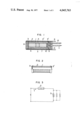
FIG. 1 is a sectional view of a sealed thermostatic heater in accordance with one embodiment of the present invention.
FIG. 2 is a fragmentary sectional view of a cylindrical heater to be used in the above thermostatic heater.
FIG. 3 is a circuit diagram of the thermostatic heater.
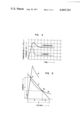
FIG. 4 shows a temperature rise characteristic curve at a point X of the thermostatic heater.
FIG. 5 shows an operational characteristic curve of the thermostatic heater.
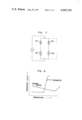
FIG. 6 is a sectional view of a sealed thermostatic heater in accordance with another embodiment of the present invention.
FIG. 7 is an electrical circuit diagram thereof.
FIG. 8 shows a resistance-temperature curve of the thermostatic heater of FIG. 6.
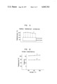
FIG. 9 shows a surface temperature distribution of the thermostatic heater of FIG. 6.
FIG. 10 shows a voltage characteristic of the thermostatic heater of FIG. 6.
Referring to FIG. 1, a cylindrical ceramic tube 1 as shown in FIG. 2 has a cylindrical heater 2 comprising a wire-wound heater or coated heater mounted on an outer peripheral surface of the ceramic tube 1. Terminal 3, 3' are attached to opposite ends of the cylindrical ceramic tube 1, one of the terminal plates, 3', being formed in a ring shape. Cylindrical, metallic radiators 4, 4' and a PTC thermistor 5 are housed in a hole formed in the ceramic tube 1 such that the PTC thermistor 5 is held by the metallic radiators 4, 4' therebetween. A metal tube 6 having one end closed, a tubular insulator 7 housed in the tube 6, and insulating circular plate 8, an insulating plate 9 having a reduced section which is adapted to be inserted into the ceramic tube 1 and bores through which lead wires extend, and a resilient metal terminal 10 are provided, the metallic radiators 4, 4' and the PTC thermistor 5 being urged toward each other by the resilient force of the metal terminal 10. A lead wire 11 is connected to the metal terminal 10 and a lead wire 12 is connected to the terminal plate 3', the lead wires 11 and 12 being connected to a power supply (not shown). As insulative sealing material 13 closes the opening of the metal tube 6. FIG. 3 shows the electrical circuit of the above sealed thermostatic heater in which the heater 2 and the PTC thermistor 5 are connected in series.
While one thermistor 5 is housed in the ceramic tube 1 in the above embodiment, a plurality of PTC thermistors may be housed in the ceramic tube 1 and a plurality of PTC thermistors may be connected in parallel as shown in FIG. 3.
FIGS. 4 and 5 show an operation characteristic of the thermostatic heater of the present invention. Upon power being turned on, the resistance of the PTC thermistor is so low that most of the power supply voltage E is applied to the cylindrical heater 2. As a result, the heater 2 operates at a point A1 in FIG. 5 so that the heater 2 generates heat and the surface temperature of the tube 6 rapidly rises. Thereafter, when the PTC thermistor 5 reaches a predetermined temperature, the resistance thereof suddenly increases, attenuating the current to stabilize itself at a fixed temperature. That is, it stabilizes at a point A2 in FIG. 5. In FIG. 5, the curve a1 shows the initial current-voltage characteristic curve of the PTC thermistor 5, the curve a2 shows the stabilized current-voltage characteristic curve of the PTC thermistor 5, and the curve b shows the load curve of the cylindrical heater 2.
With the sealed thermistor heater of the above construction in accordances with the present invention, the following advantages are presented.
1. The surface temperature rise rate is very fast. For example, for a cylindrical heater (outer diameter 16 mm, length 60 mm) having a resistance of 250 Ω and a PTC thermistor (outer diameter 10 mm, thickness 4 mm) having a resistance of 15 Ω at 25° C. and a Curie point of 230° C. at which the resistance thereof suddenly increases, the temperature at the point X (see FIG. 1) reached 200° C. one and a half minutes after the power is turned on with an applied voltage of 100 V A.C., and showed a maximum temperature of 260° C. in 2.6 minutes, and thereafter the temperature fell and stabilized at 192° C. after 4 minutes. The initial current was 330 mA and the stabilized current was 143 mA. As seen from the above experimental result, the temperature rise characteristic on the outer peripheral surface of the thermostatic heater has been remarkably improved.
2. The unevenness in the surface temperature is small. Since the PTC thermistor self-heats and the heat generated thereby is effectively transmitted to the opposite ends of the heater, the unevenness in temperature is very small. Furthermore, even if the PTC thermistor is small, the allowable power dissipation may be large because of the high heat dissipation effect.
3. High reliability. Since the PTC thermistor is used rather than a bimetal strip switch, the contactless temperature control is attained without using any movable parts. Therefore the reliability is very high. The stability of the connection against heat expansion and contraction is fully insured because it is compressively held by the resilient metal terminal.
4. Inexpensive to manufacture. Since the PTC thermistor may be of circular plate type which is easy to make and may be of small size, the heater can be manufactured at low cost.
FIGS. 6 and 7 shows another embodiment of the present invention. In FIG. 6 a cylindrical, hollow ceramic case 101 can be divided into two parts. Housed in the ceramic case 101 are resilient terminal plates 103, cylindrical metallic radiators 104, circular PTC thermistors 105, and circular ceramic heaters 102, the metallic radiator 104, the PTC thermistor 105, the metallic radiator 104, the ceramic heater 102 and the metallic radiator 104 being held in this order by and between the terminal plates 103. Lead wires 111, 112 are connected to the terminal plates 103, and the ceramic case 101 which houses the terminal plates 103, the metallic radiators 104, the PTC thermistors 105, the tubular insulator 107 and the ceramic heaters 102 is housed in a metal tube 106 as shown in FIG. 6. A sealing material 113 is provided.
FIG. 7 shows an electrical circuit of the sealed thermostatic heater shown in FIG. 6 in which two sets of series combination of the PTC thermistor 105 and the ceramic heater 102 are connected in parallel. The series combination of the PTC thermistor 105 and the ceramic heater 102 may be one, or a plurality of such combinations may be connected in parallel. As shown in the resistance-temperature characteristic of FIG. 8, the ceramic heater 102 has a higher initial resistance than the PTC thermistor 105 so that upon power being turned on the heat is generated primarily by the ceramic heater 102. When the PTC thermistor 105 reaches a predetermined temperature the resistance thereof suddenly increases, attenuating the current to thereby maintain the temperature at a constant value. Further, in its construction, since the metallic radiators 104 are arranged in the ceramic case 101 such that they may contact with the electrode surfaces of the ceramic heaters 102 and the PTC thermistors 105, the entire surface of the metal tube 106 may readily posses uniform temperature distribution, as shown in FIG. 9.
According to the sealed thermostatic heater of the present invention thus constructed, the following advantages are presented;
1. Since the cylindrical metallic radiators are arranged to make contact with the electrodes of the circular ceramic heaters, the temperature rise rate of the metallic tube surface is very fast. Although the heating surface of the ceramic heater per se is very small, since the metallic radiators are in contact with the electrode surfaces, the heat from the ceramic heater is transmitted over a wide area in a short time period and the heating surface of the metallic tube is large resulting in the improvement of the temperature rise characteristic.
2. Since the heat of the ceramic heater is directly received by the PTC thermistor through the metallic radiator, the heater operates stably at the correct temperature. Under the stabilized condition, the ceramic heater and the PTC thermistor generate the heat so that a wide heating surface may be provided through the radiator.
3. In general, the heat generated by the ceramic heater and the PTC thermistor under the stabilized condition changes depending on the unevenness of the characteristics of the respective elements and such unevenness results in the unevenness of the surface temperature distribution (temperature at various points) of the metal tube. By sorting the characteristics of the elements and taking the balance of the positioning of the elements by changing the width of the metallic radiator, the temperature distribution can be readily unified.
4. Since the shapes of the ceramic heater and the PTC thermistor are of conventional circular type they can be very readily manufactured in small size with low cost. Because of the metallic radiator the electrical connection is also easily made and the assembly thereof is simple.
5. Since the PTC thermistor is used in the sealed thermostatic heater of the present invention, the power dissipation and the heater temperature remain substantially unchanged even if the power supply voltage changes, as seen from the voltage characteristic curve of FIG. 10.
Claims (4)
1. A sealed thermostatic heater comrpising a ceramic tube having at least one PTC thermistor and at least two metallic radiators housed therein, said PTC thermistor being held by and between said radiators, said ceramic tube being sealed in a metal tube, and PTC thermistor and a heater in said metal tube being electrically connected in series.
2. A sealed thermostatic heater comprising a ceramic tube having at least one PTC thermistor and at least two metallic radiators housed therein and a heater arranged at an outer periphery thereof, said PTC thermistor being held by and between said radiators, said ceramic tube being sealed in a metal tube, said PTC thermistor and said heater being electrically connected in series.
3. A sealed thermostatic heater according to claim 2, wherein a terminal plate fit to one end of said ceramic tube and said heater are electrically connected in series, said radiator, said PTC thermistor and said radiator are inserted, in this order, into said ceramic tube, said radiators and said PTC thermistor are held by and between said terminal plate and a resilient metal terminal forcibly inserted into said ceramic tube, and said heater and said PTC thermistor are connected in series through said terminal plate.
4. A sealed thermostatic heater comprising a ceramic tube having at least one series circuit housed therein, said series circuit including a disc type ceramic heater conductively held between a pair of metallic radiators and a disc type PTC thermistor conductively held between another pair of metallic radiators, said ceramic tube being inserted into a metal tube.
Applications Claiming Priority (4)
| Application Number | Priority Date | Filing Date | Title |
|---|---|---|---|
| JA49-141083[U] | 1974-11-20 | ||
| JP14108374U JPS5438610Y2 (en) | 1974-11-20 | 1974-11-20 | |
| JP962475U JPS5191342U (en) | 1975-01-20 | 1975-01-20 | |
| JA50-9624[U] | 1975-01-20 |
Publications (1)
| Publication Number | Publication Date |
|---|---|
| US4045763A true US4045763A (en) | 1977-08-30 |
Family
ID=26344386
Family Applications (1)
| Application Number | Title | Priority Date | Filing Date |
|---|---|---|---|
| US05/633,230 Expired - Lifetime US4045763A (en) | 1974-11-20 | 1975-11-19 | Sealed thermostatic heater |
Country Status (6)
| Country | Link |
|---|---|
| US (1) | US4045763A (en) |
| CA (1) | CA1050093A (en) |
| DE (1) | DE2551980B2 (en) |
| FR (1) | FR2292395A1 (en) |
| GB (1) | GB1502479A (en) |
| IT (1) | IT1052333B (en) |
Cited By (28)
| Publication number | Priority date | Publication date | Assignee | Title |
|---|---|---|---|---|
| US4223208A (en) * | 1978-04-13 | 1980-09-16 | Siemens Aktiengesellschaft | Heater with a ferro-electric ceramic heating element |
| US4236065A (en) * | 1978-12-06 | 1980-11-25 | Texas Instruments Incorporated | Self-regulating electric heater |
| US4282003A (en) * | 1978-12-06 | 1981-08-04 | Texas Instruments Incorporated | Method for constructing a self-regulating electric heater |
| US4316080A (en) * | 1980-02-29 | 1982-02-16 | Theodore Wroblewski | Temperature control devices |
| WO1982003693A1 (en) * | 1981-04-09 | 1982-10-28 | Inc Rosemount | Passive temperature control arrangement for fluid flow stream sensor heater |
| US4371778A (en) * | 1978-09-15 | 1983-02-01 | Siemens Aktiengesellschaft | Electric heating device employing PTC heating element for preheating of heating oil |
| US4574188A (en) * | 1982-04-16 | 1986-03-04 | Raychem Corporation | Elongate electrical assemblies |
| US4582983A (en) * | 1982-04-16 | 1986-04-15 | Raychem Corporation | Elongate electrical assemblies |
| US4659913A (en) * | 1982-04-16 | 1987-04-21 | Raychem Corporation | Elongate electrical assemblies |
| US4791272A (en) * | 1986-10-24 | 1988-12-13 | Windmere Corporation | PTC hair roller |
| US4791276A (en) * | 1982-04-16 | 1988-12-13 | Raychem Corporation | Elongate electrical assemblies |
| US4794229A (en) * | 1987-04-24 | 1988-12-27 | Thermon Manufacturing Company | Flexible, elongated thermistor heating cable |
| US4937435A (en) * | 1987-12-14 | 1990-06-26 | Thermon Manufacturing Company | Flexible electric heating pad using PTC ceramic thermistor chip heating elements |
| US5354967A (en) * | 1992-11-13 | 1994-10-11 | Helen Of Troy Corporation | Hair styling appliance heater and control |
| US5414241A (en) * | 1992-05-11 | 1995-05-09 | Sekisui Kaseihin Kogyo Kabushiki Kaisha | Heater, a method of manufacturing the same, and an anti-condensation mirror incorporating the same |
| US5571432A (en) * | 1992-04-21 | 1996-11-05 | Valeo Thermique Habitacle | Heating and ventilating apparatus for the cabin of a motor vehicle having a propulsion motor with relatively low heat loss |
| US5601742A (en) * | 1993-09-03 | 1997-02-11 | Texas Instruments Incorporated | Heating device for an internal combustion engine with PTC elements having different curie temperatures |
| US5866882A (en) * | 1994-12-15 | 1999-02-02 | Behr-Thomson-Dehnstoffregler Gmbh & Co. | Thermostatic working element having an electric resistance heating element and method of making same |
| US6720536B2 (en) * | 2001-12-06 | 2004-04-13 | Catem Gmbh & Co., Kg | Electric heating device |
| US20040163662A1 (en) * | 2003-01-16 | 2004-08-26 | Conair Corporation | Hair roller with a ceramic coating |
| EP1545158A2 (en) * | 2003-12-20 | 2005-06-22 | Gustav Wahler GmbH u. Co.KG | Heating device, in particular heating device for a thermostatic operational element of a valve of a thermostat |
| US7034259B1 (en) | 2004-12-30 | 2006-04-25 | Tom Richards, Inc. | Self-regulating heater assembly and method of manufacturing same |
| US20130125531A1 (en) * | 2009-12-24 | 2013-05-23 | Inergy Automotive Systems Research (Societe Anonyme) | Reservoir and tank equipped with a self-regulating heating element |
| JP2013536699A (en) * | 2010-08-31 | 2013-09-26 | ジェメラ・リミテッド | Hair styling equipment |
| US20180176991A1 (en) * | 2015-12-08 | 2018-06-21 | Temp4 Inc. | Efficient Assembled Heating Elements of Large Sizes and of Metallic Tubular Designs for Electric Radiant Heaters |
| CN109449901A (en) * | 2018-12-05 | 2019-03-08 | 丹东国通电子元件有限公司 | Ceramic PTC therefore high pulse power load protector |
| US11191335B2 (en) * | 2012-06-25 | 2021-12-07 | Jemella Limited | Hair styling appliance |
| US20220126650A1 (en) * | 2019-11-14 | 2022-04-28 | Lexmark International, Inc. | Cabin heater for vehicle |
Families Citing this family (11)
| Publication number | Priority date | Publication date | Assignee | Title |
|---|---|---|---|---|
| US4563571A (en) * | 1981-12-16 | 1986-01-07 | Matsushita Electric Industrial Company, Limited | Electric water heating device with decreased mineral scale deposition |
| DE3246775A1 (en) * | 1982-12-17 | 1984-07-12 | Robert 7990 Friedrichshafen Kolb jun. | Heating apparatus which can be heated electrically |
| GB8417547D0 (en) * | 1984-07-10 | 1984-08-15 | Dreamland Electrical Apliances | Electric blankets |
| DE3544589C2 (en) * | 1985-12-17 | 1994-01-13 | Wolf Woco & Co Franz J | Heated element of a windscreen washer system for motor vehicles |
| NL8600142A (en) * | 1986-01-23 | 1987-08-17 | Philips Nv | METHOD FOR MANUFACTURING A SELF-REGULATING HEATING ELEMENT |
| DE3617679A1 (en) * | 1986-05-26 | 1987-12-03 | Stego Elektrotechnik Gmbh | ELECTRIC RADIATOR |
| DE3709285A1 (en) * | 1987-03-20 | 1988-09-29 | Tuerk & Hillinger Gmbh | Electrical heating cartridge having an intrinsically different power emission |
| DE3717574A1 (en) * | 1987-05-25 | 1988-12-15 | Ruthenberg Gmbh Waermetechnik | DEVICE FOR HEATING AREAS IN OR ON MOTOR VEHICLES, FOR EXAMPLE SEATS, WINDOWS, MIRRORS, OR THE LIKE |
| DE8717467U1 (en) * | 1987-09-09 | 1989-04-27 | Eltra Gmbh & Co Kg Leicht & Trambauer, 6102 Pfungstadt, De | |
| CN101902846A (en) * | 2010-07-21 | 2010-12-01 | 张福民 | Nano-silicon conductive ceramic electrical heating tube element and manufacture method thereof |
| GB2613777A (en) * | 2021-12-03 | 2023-06-21 | Amphenol Thermometrics Inc | Heating unit |
Citations (2)
| Publication number | Priority date | Publication date | Assignee | Title |
|---|---|---|---|---|
| US1279321A (en) * | 1916-01-19 | 1918-09-17 | Seymour Stedman | Electrically-heated soldering-iron. |
| US3023295A (en) * | 1958-07-30 | 1962-02-27 | Hexacon Electric Company | Electric soldering iron of the instant heat type |
Family Cites Families (6)
| Publication number | Priority date | Publication date | Assignee | Title |
|---|---|---|---|---|
| GB297503A (en) * | 1927-06-24 | 1928-09-24 | Walter Rosenhain | Improvements relating to electric heating devices for use in electric furnaces, domestic heating appliances and the like |
| JPS4941732Y1 (en) * | 1968-11-29 | 1974-11-15 | ||
| US3586642A (en) * | 1968-05-29 | 1971-06-22 | Matsushita Electric Ind Co Ltd | Ptc thermistor of bati03,and other oxides |
| DE1922206C3 (en) * | 1969-04-30 | 1973-10-04 | Siemens Ag, 1000 Berlin U. 8000 Muenchen | Thermostat with ceramic PTC thermistors as self-regulating heating resistances for quartz oscillators |
| US3673538A (en) * | 1969-12-05 | 1972-06-27 | Texas Instruments Inc | Composite thermistor temperature sensor having step-function response |
| US3632971A (en) * | 1970-01-27 | 1972-01-04 | Texas Instruments Inc | Self-limiting electric hair curler heater |
-
1975
- 1975-11-18 GB GB47561/75A patent/GB1502479A/en not_active Expired
- 1975-11-18 FR FR7535159A patent/FR2292395A1/en active Granted
- 1975-11-19 DE DE2551980A patent/DE2551980B2/en not_active Withdrawn
- 1975-11-19 US US05/633,230 patent/US4045763A/en not_active Expired - Lifetime
- 1975-11-19 CA CA240,007A patent/CA1050093A/en not_active Expired
- 1975-11-19 IT IT7552298A patent/IT1052333B/en active
Patent Citations (2)
| Publication number | Priority date | Publication date | Assignee | Title |
|---|---|---|---|---|
| US1279321A (en) * | 1916-01-19 | 1918-09-17 | Seymour Stedman | Electrically-heated soldering-iron. |
| US3023295A (en) * | 1958-07-30 | 1962-02-27 | Hexacon Electric Company | Electric soldering iron of the instant heat type |
Cited By (34)
| Publication number | Priority date | Publication date | Assignee | Title |
|---|---|---|---|---|
| US4223208A (en) * | 1978-04-13 | 1980-09-16 | Siemens Aktiengesellschaft | Heater with a ferro-electric ceramic heating element |
| US4371778A (en) * | 1978-09-15 | 1983-02-01 | Siemens Aktiengesellschaft | Electric heating device employing PTC heating element for preheating of heating oil |
| US4236065A (en) * | 1978-12-06 | 1980-11-25 | Texas Instruments Incorporated | Self-regulating electric heater |
| US4282003A (en) * | 1978-12-06 | 1981-08-04 | Texas Instruments Incorporated | Method for constructing a self-regulating electric heater |
| US4316080A (en) * | 1980-02-29 | 1982-02-16 | Theodore Wroblewski | Temperature control devices |
| US4458137A (en) * | 1981-04-09 | 1984-07-03 | Rosemount Inc. | Electric heater arrangement for fluid flow stream sensors |
| WO1982003693A1 (en) * | 1981-04-09 | 1982-10-28 | Inc Rosemount | Passive temperature control arrangement for fluid flow stream sensor heater |
| US4574188A (en) * | 1982-04-16 | 1986-03-04 | Raychem Corporation | Elongate electrical assemblies |
| US4582983A (en) * | 1982-04-16 | 1986-04-15 | Raychem Corporation | Elongate electrical assemblies |
| US4659913A (en) * | 1982-04-16 | 1987-04-21 | Raychem Corporation | Elongate electrical assemblies |
| US4791276A (en) * | 1982-04-16 | 1988-12-13 | Raychem Corporation | Elongate electrical assemblies |
| US4791272A (en) * | 1986-10-24 | 1988-12-13 | Windmere Corporation | PTC hair roller |
| US4794229A (en) * | 1987-04-24 | 1988-12-27 | Thermon Manufacturing Company | Flexible, elongated thermistor heating cable |
| US4937435A (en) * | 1987-12-14 | 1990-06-26 | Thermon Manufacturing Company | Flexible electric heating pad using PTC ceramic thermistor chip heating elements |
| US5571432A (en) * | 1992-04-21 | 1996-11-05 | Valeo Thermique Habitacle | Heating and ventilating apparatus for the cabin of a motor vehicle having a propulsion motor with relatively low heat loss |
| US5414241A (en) * | 1992-05-11 | 1995-05-09 | Sekisui Kaseihin Kogyo Kabushiki Kaisha | Heater, a method of manufacturing the same, and an anti-condensation mirror incorporating the same |
| US5354967A (en) * | 1992-11-13 | 1994-10-11 | Helen Of Troy Corporation | Hair styling appliance heater and control |
| US5601742A (en) * | 1993-09-03 | 1997-02-11 | Texas Instruments Incorporated | Heating device for an internal combustion engine with PTC elements having different curie temperatures |
| US5866882A (en) * | 1994-12-15 | 1999-02-02 | Behr-Thomson-Dehnstoffregler Gmbh & Co. | Thermostatic working element having an electric resistance heating element and method of making same |
| US6720536B2 (en) * | 2001-12-06 | 2004-04-13 | Catem Gmbh & Co., Kg | Electric heating device |
| US6945255B2 (en) | 2003-01-16 | 2005-09-20 | Conair Corporation | Hair roller with a ceramic coating |
| US20040163662A1 (en) * | 2003-01-16 | 2004-08-26 | Conair Corporation | Hair roller with a ceramic coating |
| EP1545158A3 (en) * | 2003-12-20 | 2005-10-19 | Gustav Wahler GmbH u. Co.KG | Heating device, in particular heating device for a thermostatic operational element of a valve of a thermostat |
| EP1545158A2 (en) * | 2003-12-20 | 2005-06-22 | Gustav Wahler GmbH u. Co.KG | Heating device, in particular heating device for a thermostatic operational element of a valve of a thermostat |
| US7034259B1 (en) | 2004-12-30 | 2006-04-25 | Tom Richards, Inc. | Self-regulating heater assembly and method of manufacturing same |
| US20130125531A1 (en) * | 2009-12-24 | 2013-05-23 | Inergy Automotive Systems Research (Societe Anonyme) | Reservoir and tank equipped with a self-regulating heating element |
| US9422849B2 (en) * | 2009-12-24 | 2016-08-23 | Inergy Automotive Systems Research (Societe Anonyme) | Reservoir and tank equipped with a self-regulating heating element |
| JP2013536699A (en) * | 2010-08-31 | 2013-09-26 | ジェメラ・リミテッド | Hair styling equipment |
| US9808061B2 (en) | 2010-08-31 | 2017-11-07 | Jemella Ltd. | Hair styling appliance |
| US11191335B2 (en) * | 2012-06-25 | 2021-12-07 | Jemella Limited | Hair styling appliance |
| US20180176991A1 (en) * | 2015-12-08 | 2018-06-21 | Temp4 Inc. | Efficient Assembled Heating Elements of Large Sizes and of Metallic Tubular Designs for Electric Radiant Heaters |
| US10542587B2 (en) * | 2015-12-08 | 2020-01-21 | Temp4 Inc. | Heating elements of large sizes and of metallic tubular designs |
| CN109449901A (en) * | 2018-12-05 | 2019-03-08 | 丹东国通电子元件有限公司 | Ceramic PTC therefore high pulse power load protector |
| US20220126650A1 (en) * | 2019-11-14 | 2022-04-28 | Lexmark International, Inc. | Cabin heater for vehicle |
Also Published As
| Publication number | Publication date |
|---|---|
| IT1052333B (en) | 1981-06-20 |
| GB1502479A (en) | 1978-03-01 |
| DE2551980A1 (en) | 1976-05-26 |
| DE2551980B2 (en) | 1980-04-17 |
| FR2292395A1 (en) | 1976-06-18 |
| FR2292395B1 (en) | 1980-08-14 |
| CA1050093A (en) | 1979-03-06 |
Similar Documents
| Publication | Publication Date | Title |
|---|---|---|
| US4045763A (en) | Sealed thermostatic heater | |
| US3976854A (en) | Constant-temperature heater | |
| US4151401A (en) | PTC heating device having selectively variable temperature levels | |
| US4238812A (en) | Circuit protection devices comprising PTC elements | |
| US3720807A (en) | Food warming apparatus | |
| JPH0359558B2 (en) | ||
| US4107640A (en) | Current limiting element for preventing electrical overcurrent | |
| US4401885A (en) | Planar heat generating device | |
| US6310322B1 (en) | Heated roller and heated roller assembly | |
| US2575113A (en) | Igniter | |
| US3713062A (en) | Snap disc thermal sequencer | |
| US3521138A (en) | Thermal starting device for a singlephase asynchronous motor | |
| US4730103A (en) | Compact PTC resistance heater | |
| US3973100A (en) | Self-limiting electric hair curler heater | |
| US4287500A (en) | Thermal protector | |
| US4591820A (en) | Thermostatic electric switch and thermal biasing assembly therefor | |
| US4267635A (en) | Method of making a solid state electrical switch | |
| US3593248A (en) | Thermal control means | |
| US4646051A (en) | Thermostatic electric switch and thermal biasing assembly therefor | |
| US4754251A (en) | Thermostatic electric switch and thermal biasing assembly therefor | |
| JPH028608Y2 (en) | ||
| US2336504A (en) | Thermostatic switch | |
| JPH0134317Y2 (en) | ||
| JPS5833668Y2 (en) | Tsutsugatahita | |
| JPH0140617Y2 (en) |