US4065885A - Portable building structure - Google Patents
Portable building structure Download PDFInfo
- Publication number
- US4065885A US4065885A US05/438,877 US43887774A US4065885A US 4065885 A US4065885 A US 4065885A US 43887774 A US43887774 A US 43887774A US 4065885 A US4065885 A US 4065885A
- Authority
- US
- United States
- Prior art keywords
- corner
- corner posts
- flanges
- members
- frame members
- Prior art date
- Legal status (The legal status is an assumption and is not a legal conclusion. Google has not performed a legal analysis and makes no representation as to the accuracy of the status listed.)
- Expired - Lifetime
Links
Images


Classifications
-
- E—FIXED CONSTRUCTIONS
- E04—BUILDING
- E04H—BUILDINGS OR LIKE STRUCTURES FOR PARTICULAR PURPOSES; SWIMMING OR SPLASH BATHS OR POOLS; MASTS; FENCING; TENTS OR CANOPIES, IN GENERAL
- E04H1/00—Buildings or groups of buildings for dwelling or office purposes; General layout, e.g. modular co-ordination or staggered storeys
- E04H1/12—Small buildings or other erections for limited occupation, erected in the open air or arranged in buildings, e.g. kiosks, waiting shelters for bus stops or for filling stations, roofs for railway platforms, watchmen's huts or dressing cubicles
- E04H1/1205—Small buildings erected in the open air
- E04H1/1216—Public W.C.s
Definitions
- the present invention provides a novel portable building structure which is inexpensive to manufacture and which is composed of relatively few components.
- the components separately interfit with one another so that the building structure may be transported in a knocked-down, compact form, and at any desired location, the building structure may be erected quickly without substantial labor, and correspondingly, later knocked-down for transfer to another location.
- the invention provides a portable building structure wherein the frame may be composed of elongated extrusions cut to suitable lengths and corresponding forms for providing, when assembled with flooring, a base or floor structure which is adapted to receive upright corner members so constructed as to accomodate suitable side wall panels.
- a ceiling structure composed of components generally similar to the floor, is placed upon the corner posts, thereby interlocking the assembly together.
- the side wall panels may vary depending upon the intended utility of the portable building structure.
- the side wall panels may be provided with, or have incorporated therein, various ventilators, windows or doors.
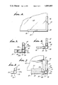
- FIG. 1 is a perspective of the portable sanitary facility incorporating the invention
- FIG. 2 is an enlarged fragmentary view, partly in elevation with parts broken away, and showing a typical connection between the elements of the building structure as taken generally on the line 2--2 of FIG. 1;
- FIG. 3 is a view in vertical section, as taken on the line 3--3 of FIG. 2;
- FIG. 4 is a fragmentary detail view in plan, as taken on the line 4--4 of FIG. 2;
- FIG. 5 is a fragmentary detail view in horizontal section, as taken on the line 5--5 of FIG. 2;
- FIG. 6 is a fragmentary detail view in horizontal section, as taken on the line 6--6 of FIG. 2;
- FIG. 7 is a fragmentary detail view in horizontal section, as taken on line 7--7 of FIG. 2;
- FIG. 8 is an exploded view in perspective illustrating the partially assembled building structure
- FIG. 9 is a fragmentary detail view in section, as taken on the line 9--9 of FIG. 8, showing a typical corner post
- FIG. 10 is a fragmentary detail view of a representative corner assembly more particularly illustrating the clamping of the panels.
- the invention is shown as being incorporated in a portable building structure B of the type employed to house a toilet T, such as typical chemical toilet, for example.
- the building B has a base or floor structure 10, adapted to be mounted in a pallet P, a ceiling or roof structure 11, side walls 12, 12, a rear wall 13, and a front wall 14, all of which are adapted to be quickly and conveniently assembled and disassembled, without requiring skilled labor or special tools.
- the base structure 10 is constructed of corner elements 15 which preferably consist, respectively, of corresponding sections of an elongated extrusion, say of aluminum.
- Each corner element 15 has a body section 16 having a socket 17 of generally rectangular configuration.
- the body 15 has an outer vertical rib 18.
- side flanges 19 Projecting from the body 16 are side flanges 19 which are disposed at a right angle which includes the body 16.
- base frame members 20 Extending horizontally between the corner members 15 and suitably affixed to the respective flanges 19, as by blind rivets 19a, are base frame members 20, which as seen in FIG. 3 are generally rectangular in section, but, if preferred, channel members may be employed.
- These frame members 20 have inwardly projecting, horizontally extended and vertically spaced flanges 21 adapted to receive a suitable flooring panel or flooring member 22.
- the flooring 22 is retained in place in the flanges 21 when the frame members 20 and the corner members 15 are interconnected as seen in FIG. 7.
- the frame members 20 have an upwardly opening channel 23 adapted to receive the respective side, rear and front walls, as will be later described.
- a floor structure which is unitized and which has at its respective four corners the sockets 17 adapted to receive vertical wall supporting corner posts respectively designated 24 which are adapted to be removably engaged in the socket 17, as will later be described, and to support the ceiling or roof structure 11, as will also be later described.
- each of the corner posts 24 has an intermediate elongated section between its upper and lower ends which consists of a body portion 25, having a beveled edge wall 26 to eliminate sharp corners, and having the integral with the body 25 channel sections or flanges 27 projecting laterally at a right angle including the body section 25 and providing grooves 28 adapted to receive the respective side, front and rear walls of the building structure, one of the side walls 12 and the front wall 14 being seen in FIG. 6.
- each of them has its channel sections or flanges 27 cut back longitudinally to expose end body portions 25a.
- the lower end body portion 25a of the respective corner posts 24 is adapted to fit into the socket 17 of one of the corner members 15 of the floor structure 10.
- the respective wall panels 12, 13 and 14 are, as previously indicated, adapted to be received in the channels 28 of the corner posts 24, and the assembly procedure may involve placing a first corner post in one of the sockets 17, and then laterally installing one of the wall panels; thereafter installing the second corner post onto the exposed edge of the wall panel and slightly vertically spaced above the floor structure 10, whereupon the second corner post may then be lowered into its socket 17.
- This operation can be repeated through three of the wall panels, and the fourth wall panel may be either inserted vertically into the opposed slots 28 of the channel sections 27 of the corner post 24 or the opposing posts which support the fourth wall panel may be slightly spread apart to allow the fourth wall panel to be inserted there between.
- Suitable means such as set screws 18a threaded in the ridges 18 of the corner members 15 and engaged with the post sections 25a, are employed to retain the floor structure assembled.
- the roof structure 11, as best seen in FIGS. 4 and 5 consists of corner members 30 generally corresponding to the corner members 15 of the floor structure, and preferably made from the same extrusions.
- the corner members 30 each comprise a body section 31 providing a socket 32 adapted to receive an end portion 25a of the respective corner posts 24, and the outer ridge 33 is adapted to receive a locking screw 33a whereby the roof structure may be securely retained upon the corner posts 24 by the simple expedient of tightening the screws at the respective four corners.
- the right angularly related flanges 34 Projecting from the body section 31 of the upper corner members 30 are the right angularly related flanges 34 to which, as by rivets 34a, are secured horizontally extended rectangular roof supporting frame members 35, which like the lower supporting frame members 20 may be either of rectangular form or channel members providing at its upper edge, vertically spaced flanges 36 adapted to receive a ceiling panel 37, say of translucent plastic for an edge wall 38 interconnects the flanges 36 and is preferably spaced outwardly, as seen in FIG. 3, from the body of the frame member 35, so as to overly the corner members 30 at the mitered corners 39 of the ceiling frame members 35, as seen in FIG. 8.
- the ceiling frame members 35 also have downwardly projecting, spaced flanges 40 forming a downwardly opening channels for receiving the upper edges of the respective walls 12, 13 and 14, when the assembled ceiling structure is placed upon the upper edges of the walls 12, 13 and 14 and the end portions 25a of the corner posts 24 are engaged in the sockets 32 in the respective corner members 30 of the roof structure 11.
- the building B as disclosed herein, is shown as a portable sanitary building containing the toilet T, the details of which are immaterial to the present invention.
- the toilet T comprises a suitable base 45 adapted to rest upon the floor panel 22, and having the usual toilet seat 46 hingedly mounted thereon.
- a vent pipe 47 extends upwardly from the base 45 and has an upper threaded end 48 adapted to extend through a complemental opening 49 in the ceiling panel 37 and to receive a vent cap 50, which, as seen in FIG. 1, is adapted to closely seat atop of the ceiling panel 37.
- the respective side walls 12 and the rear wall 13 are each provided with suitable ventilator panels 51, such as the louvered panels shown herein, or if desired other forms of ventilatin means may be employed.
- the front wall 14, in the illustrative embodiment includes a door frame 52, which, without need for specific illustrations herein, may consist of suitable channel members of extrusions cut to length to fit upon the front wall panel 14 on the edge of a door opening. Hingedly mounted at 53 within the door frame 52 is a door 54 having suitable pull 55 attached thereto. It will be appreciated that, as may be required by various regulation suitable latch means and spring means may be provided to normally loa the door 54 to a closed and latched position. Alternatively, again, without need of further specific illustration, it will be understood that various other door forms may be employed where, as for example, the portable building B is to be employed as a ticket booth, guard house or the like.
- the present invention provides a portable building structure which may be conveniently erected or knocked down and the various components thereof may be of different porportions than herein illustrated.
- the building herein illustrated is essentially square, but the building may be made wider or longer simply by extending the length of the extruded elements of the base frame members 20 and the ceiling frame members 35.
- intermediate post elements might be employed, where necessary, for rigidity.
- the portable building structure B herein is shown as being disposed upon a pallet P such a pallet is not necessary in the event that the building is to be erected on firm ground, but such a pallet is desirable, say, where the portable building is to be mounted on soft or sandy soil so as to maintain the building in an upright condition, and to prevent the building from sinking into the soil.
- the base or floor structure 10 may be fastened to the pallet P by suitable fastenings 60, as seen in FIG. 3, which extend through a horizontally extended flange 61 formed on the base frame members 20.
- the corner post 124 is somewhat smaller than the socket in which it is received, so that when the set screws 18a force the corner post inwardly, a clamping of the panels results.
- the panels forming the sides of the structure are disposed in the slots 28 of the channel section 27 of the corner post 24, with the lower edges of the panels extending downwardly into the upwardly opening channels 23 of the frame members 20 and extending upwardly into the downwardly opening channels formed by the flanges 40 of the frame members 35, the panels will be forced into frictionally locked engagement at their upper and lower edges by the action of the set screws 18a which force the corner posts 24 inwardly, whereby theouter flanges on the corner posts urge the panel edges against the inner flanges of the top and bottom frame members.
Landscapes
- Engineering & Computer Science (AREA)
- Architecture (AREA)
- Civil Engineering (AREA)
- Structural Engineering (AREA)
- Residential Or Office Buildings (AREA)
Abstract
Description
Claims (4)
Applications Claiming Priority (1)
| Application Number | Priority Date | Filing Date | Title |
|---|---|---|---|
| US27909872A | 1972-08-09 | 1972-08-09 |
Related Parent Applications (1)
| Application Number | Title | Priority Date | Filing Date |
|---|---|---|---|
| US27909872A Continuation-In-Part | 1972-08-09 | 1972-08-09 |
Publications (1)
| Publication Number | Publication Date |
|---|---|
| US4065885A true US4065885A (en) | 1978-01-03 |
Family
ID=23067628
Family Applications (1)
| Application Number | Title | Priority Date | Filing Date |
|---|---|---|---|
| US05/438,877 Expired - Lifetime US4065885A (en) | 1972-08-09 | 1974-02-01 | Portable building structure |
Country Status (1)
| Country | Link |
|---|---|
| US (1) | US4065885A (en) |
Cited By (44)
| Publication number | Priority date | Publication date | Assignee | Title |
|---|---|---|---|---|
| US4471501A (en) * | 1982-07-30 | 1984-09-18 | Hytec, Inc. | Two piece knockdown shower stall |
| DE3515906A1 (en) * | 1984-05-08 | 1985-11-14 | Oy Ekofinn AB, Lahti | PORTABLE ROOM ELEMENT |
| US4577351A (en) * | 1984-10-30 | 1986-03-25 | Poly-John Enterprises Corp. | Portable toilet cabana |
| US4689930A (en) * | 1986-05-29 | 1987-09-01 | National Gypsum Company | Partition structure |
| US4744111A (en) * | 1986-06-26 | 1988-05-17 | Satellite Industries, Inc. | Knock-down commode |
| US4974265A (en) * | 1989-08-25 | 1990-12-04 | Maggio John J | Collapsible privacy shelter |
| US5029348A (en) * | 1989-09-21 | 1991-07-09 | Brunswick Corporation | Head construction for a pontoon boat |
| US5093941A (en) * | 1989-10-19 | 1992-03-10 | Mueller Harald G | Transportable, disassemblable cabin |
| EP0481246A2 (en) * | 1990-10-16 | 1992-04-22 | CENTRO ACCIAI S.p.A. | Public lavatory with a self-supporting structure |
| FR2685726A1 (en) * | 1991-12-30 | 1993-07-02 | France Proprete Sarl | Disassemblable modular toilet closet |
| US5251342A (en) * | 1991-11-07 | 1993-10-12 | Synergy World, Inc. | Plastic portable toilet assembly |
| US5472290A (en) * | 1993-06-02 | 1995-12-05 | Altamont, Inc. | Joint with tapered edges |
| WO1999064750A1 (en) * | 1998-06-11 | 1999-12-16 | Altamont, Inc. | Monocoque composite joint |
| EP0940527A3 (en) * | 1998-03-05 | 2001-06-13 | EMMEGI S.A.S. DI GIOVANNARDI DOTT. MAURO & LORENZO MONTI | Movable structure for use as toilet |
| US6341458B1 (en) * | 2000-06-08 | 2002-01-29 | Crane Products Ltd. | Extruded composite corners for building construction |
| EP1180568A1 (en) * | 2000-08-18 | 2002-02-20 | Metal Plan | Toilet cabin |
| US6668392B2 (en) | 2002-05-13 | 2003-12-30 | Michael Mason | Enclosure for portable toilet |
| US6673097B1 (en) * | 2001-02-23 | 2004-01-06 | Hollywood Tanning Systems, Inc. | Tanning booth having reduced tanning time |
| US20040118062A1 (en) * | 2001-05-17 | 2004-06-24 | Wuestman Tuindecoraties B.V. | Connection for wall elements |
| US6758017B2 (en) * | 2001-08-27 | 2004-07-06 | Peter P. Young | Drywall inside corner device |
| US20050240248A1 (en) * | 2004-04-23 | 2005-10-27 | Venuto Ralph Sr | High pressure tanning booth |
| FR2869656A1 (en) * | 2004-05-03 | 2005-11-04 | Guy Jean Langlois | Sanitary block e.g. WC, forming structure, has modular unit with pin passing across orifices of vat`s cavity and unit`s male section, where pin has head cooperating with cleat guided by spindle integrated with vat to lock vat and unit |
| US20070074464A1 (en) * | 2005-09-09 | 2007-04-05 | U.S. Modular Solutions, Inc. | Systems and methods of constructing, assembling, and moving modular washrooms |
| US20070102960A1 (en) * | 2001-06-22 | 2007-05-10 | Booher Howard D | Trailer and trailer body construction and extruded panel for same |
| US20090313925A1 (en) * | 2007-06-05 | 2009-12-24 | Victoria Lyons | Modular building system |
| US20100101013A1 (en) * | 2008-10-27 | 2010-04-29 | Lufthansa Technik Ag | Modular Shower Cabin For Aircrafts |
| US8109044B2 (en) * | 2008-04-21 | 2012-02-07 | Digger Specialties, Inc. | Outdoor shower enclosure kit |
| US20130036681A1 (en) * | 2011-07-15 | 2013-02-14 | Raleigh William Baird, III | Skiddable Blind |
| CN103422572A (en) * | 2013-08-22 | 2013-12-04 | 南京斯贝尔复合材料有限责任公司 | Split mounting type integrated bathroom wall plate |
| US20140208667A1 (en) * | 2013-01-25 | 2014-07-31 | Keith Thompson | Aboveground safety shelter |
| EP2327609A3 (en) * | 2009-11-26 | 2014-08-20 | Faroex Ltd. | Structure including a composite panel joint |
| WO2015084918A1 (en) * | 2013-12-03 | 2015-06-11 | Worknest Llc | Collapsible and portable lactation enclosure |
| US9328498B2 (en) * | 2011-05-31 | 2016-05-03 | Chi Ping Plastic Co. Ltd. | Mobile toilet structure |
| WO2016078682A1 (en) * | 2014-11-17 | 2016-05-26 | Green Flush 7000 Holding B.V | Mobile sanitary unit |
| US9493945B2 (en) | 2014-07-18 | 2016-11-15 | Williams Scotsman, Inc. | Wall panel connecting system for modular building units |
| CN106193654A (en) * | 2016-06-29 | 2016-12-07 | 浙江亚厦装饰股份有限公司 | Toilet frame, toilet and toilet method of construction |
| ITUB20153338A1 (en) * | 2015-09-02 | 2017-03-02 | Alessio Dainelli | CABIN FOR CHEMICAL BATHROOM |
| US20170226722A1 (en) * | 2016-02-07 | 2017-08-10 | The Modern Group, Ltd. | Portable Restroom Safety Center |
| US20190090698A1 (en) * | 2017-09-28 | 2019-03-28 | Satellite Industries, Inc. | Portable restroom |
| US10272950B1 (en) | 2016-08-23 | 2019-04-30 | Extreme Trailers Llc | Load support deck for cargo carrying vehicle |
| CN109779329A (en) * | 2019-04-02 | 2019-05-21 | 青海柏马教育科技有限公司 | Merchandise sales pavilion |
| US11006793B1 (en) * | 2018-04-30 | 2021-05-18 | Chad Boudreaux | Portable toilet |
| US11293724B2 (en) * | 2020-01-14 | 2022-04-05 | United States Of America As Represented By The Secretary Of The Army | Modular guard towers and methods of construction |
| USD957000S1 (en) * | 2019-08-16 | 2022-07-05 | 3Ds Engineering Procurement Construction Suzhou Co., Ltd. | Booth |
Citations (12)
| Publication number | Priority date | Publication date | Assignee | Title |
|---|---|---|---|---|
| AT58142B (en) * | 1911-07-22 | 1913-03-10 | Reinhold Rostock | Double-walled concrete house composed of individual parts. |
| US1539537A (en) * | 1924-01-07 | 1925-05-26 | Mosler Safe Co | Safe corner construction |
| US1857913A (en) * | 1929-02-21 | 1932-05-10 | Judelson Julius | Booth construction |
| US2364083A (en) * | 1943-06-07 | 1944-12-05 | Lindsay & Lindsay | Prefabricated structure for containers and the like |
| US2838592A (en) * | 1956-03-27 | 1958-06-10 | Feketics Frank | Shielding enclosures |
| US2956705A (en) * | 1957-08-26 | 1960-10-18 | Gen Motors Corp | Cabinet framework |
| US3046614A (en) * | 1961-01-24 | 1962-07-31 | Percival H Sherron | Corner post connection for telephone booth |
| US3105271A (en) * | 1961-01-24 | 1963-10-01 | Percival H Sherron | Telephone corner assembly for telephone booths |
| GB1071700A (en) * | 1966-01-26 | 1967-06-14 | William Robert Meckelburg | Panel interconnecting member |
| US3380768A (en) * | 1964-11-02 | 1968-04-30 | Wolfensberger Paul | Profile rail and corner connecting piece |
| US3492767A (en) * | 1968-02-19 | 1970-02-03 | Core Properties Dev Corp | Prefabricated building construction |
| US3688458A (en) * | 1970-05-22 | 1972-09-05 | Us Plywood Champ Papers Inc | Structural joint |
-
1974
- 1974-02-01 US US05/438,877 patent/US4065885A/en not_active Expired - Lifetime
Patent Citations (12)
| Publication number | Priority date | Publication date | Assignee | Title |
|---|---|---|---|---|
| AT58142B (en) * | 1911-07-22 | 1913-03-10 | Reinhold Rostock | Double-walled concrete house composed of individual parts. |
| US1539537A (en) * | 1924-01-07 | 1925-05-26 | Mosler Safe Co | Safe corner construction |
| US1857913A (en) * | 1929-02-21 | 1932-05-10 | Judelson Julius | Booth construction |
| US2364083A (en) * | 1943-06-07 | 1944-12-05 | Lindsay & Lindsay | Prefabricated structure for containers and the like |
| US2838592A (en) * | 1956-03-27 | 1958-06-10 | Feketics Frank | Shielding enclosures |
| US2956705A (en) * | 1957-08-26 | 1960-10-18 | Gen Motors Corp | Cabinet framework |
| US3046614A (en) * | 1961-01-24 | 1962-07-31 | Percival H Sherron | Corner post connection for telephone booth |
| US3105271A (en) * | 1961-01-24 | 1963-10-01 | Percival H Sherron | Telephone corner assembly for telephone booths |
| US3380768A (en) * | 1964-11-02 | 1968-04-30 | Wolfensberger Paul | Profile rail and corner connecting piece |
| GB1071700A (en) * | 1966-01-26 | 1967-06-14 | William Robert Meckelburg | Panel interconnecting member |
| US3492767A (en) * | 1968-02-19 | 1970-02-03 | Core Properties Dev Corp | Prefabricated building construction |
| US3688458A (en) * | 1970-05-22 | 1972-09-05 | Us Plywood Champ Papers Inc | Structural joint |
Cited By (55)
| Publication number | Priority date | Publication date | Assignee | Title |
|---|---|---|---|---|
| US4471501A (en) * | 1982-07-30 | 1984-09-18 | Hytec, Inc. | Two piece knockdown shower stall |
| DE3515906A1 (en) * | 1984-05-08 | 1985-11-14 | Oy Ekofinn AB, Lahti | PORTABLE ROOM ELEMENT |
| US4577351A (en) * | 1984-10-30 | 1986-03-25 | Poly-John Enterprises Corp. | Portable toilet cabana |
| US4689930A (en) * | 1986-05-29 | 1987-09-01 | National Gypsum Company | Partition structure |
| US4744111A (en) * | 1986-06-26 | 1988-05-17 | Satellite Industries, Inc. | Knock-down commode |
| US4974265A (en) * | 1989-08-25 | 1990-12-04 | Maggio John J | Collapsible privacy shelter |
| US5029348A (en) * | 1989-09-21 | 1991-07-09 | Brunswick Corporation | Head construction for a pontoon boat |
| US5093941A (en) * | 1989-10-19 | 1992-03-10 | Mueller Harald G | Transportable, disassemblable cabin |
| EP0481246A2 (en) * | 1990-10-16 | 1992-04-22 | CENTRO ACCIAI S.p.A. | Public lavatory with a self-supporting structure |
| EP0481246A3 (en) * | 1990-10-16 | 1992-10-28 | Centro Acciai S.P.A. | Public lavatory with a self-supporting structure |
| US5251342A (en) * | 1991-11-07 | 1993-10-12 | Synergy World, Inc. | Plastic portable toilet assembly |
| FR2685726A1 (en) * | 1991-12-30 | 1993-07-02 | France Proprete Sarl | Disassemblable modular toilet closet |
| US5472290A (en) * | 1993-06-02 | 1995-12-05 | Altamont, Inc. | Joint with tapered edges |
| US6095715A (en) * | 1993-06-02 | 2000-08-01 | Altamont, Inc. | Monocoque composite joint |
| EP0940527A3 (en) * | 1998-03-05 | 2001-06-13 | EMMEGI S.A.S. DI GIOVANNARDI DOTT. MAURO & LORENZO MONTI | Movable structure for use as toilet |
| WO1999064750A1 (en) * | 1998-06-11 | 1999-12-16 | Altamont, Inc. | Monocoque composite joint |
| US6341458B1 (en) * | 2000-06-08 | 2002-01-29 | Crane Products Ltd. | Extruded composite corners for building construction |
| EP1180568A1 (en) * | 2000-08-18 | 2002-02-20 | Metal Plan | Toilet cabin |
| US20050065578A1 (en) * | 2001-02-23 | 2005-03-24 | Ralph Venuto | Tanning booth having reduced tanning time |
| US6673097B1 (en) * | 2001-02-23 | 2004-01-06 | Hollywood Tanning Systems, Inc. | Tanning booth having reduced tanning time |
| US20040118062A1 (en) * | 2001-05-17 | 2004-06-24 | Wuestman Tuindecoraties B.V. | Connection for wall elements |
| US7267393B2 (en) * | 2001-06-22 | 2007-09-11 | East Manufacturing Corporation | Trailer and trailer body construction and extruded panel for same |
| US20070102960A1 (en) * | 2001-06-22 | 2007-05-10 | Booher Howard D | Trailer and trailer body construction and extruded panel for same |
| US6758017B2 (en) * | 2001-08-27 | 2004-07-06 | Peter P. Young | Drywall inside corner device |
| US6668392B2 (en) | 2002-05-13 | 2003-12-30 | Michael Mason | Enclosure for portable toilet |
| US20050240248A1 (en) * | 2004-04-23 | 2005-10-27 | Venuto Ralph Sr | High pressure tanning booth |
| FR2869656A1 (en) * | 2004-05-03 | 2005-11-04 | Guy Jean Langlois | Sanitary block e.g. WC, forming structure, has modular unit with pin passing across orifices of vat`s cavity and unit`s male section, where pin has head cooperating with cleat guided by spindle integrated with vat to lock vat and unit |
| US20070074464A1 (en) * | 2005-09-09 | 2007-04-05 | U.S. Modular Solutions, Inc. | Systems and methods of constructing, assembling, and moving modular washrooms |
| US20090313925A1 (en) * | 2007-06-05 | 2009-12-24 | Victoria Lyons | Modular building system |
| US8109044B2 (en) * | 2008-04-21 | 2012-02-07 | Digger Specialties, Inc. | Outdoor shower enclosure kit |
| US20100101013A1 (en) * | 2008-10-27 | 2010-04-29 | Lufthansa Technik Ag | Modular Shower Cabin For Aircrafts |
| EP2327609A3 (en) * | 2009-11-26 | 2014-08-20 | Faroex Ltd. | Structure including a composite panel joint |
| US9328498B2 (en) * | 2011-05-31 | 2016-05-03 | Chi Ping Plastic Co. Ltd. | Mobile toilet structure |
| US20130036681A1 (en) * | 2011-07-15 | 2013-02-14 | Raleigh William Baird, III | Skiddable Blind |
| US20140208667A1 (en) * | 2013-01-25 | 2014-07-31 | Keith Thompson | Aboveground safety shelter |
| US8955262B2 (en) * | 2013-01-25 | 2015-02-17 | Keith Thompson | Aboveground safety shelter |
| US9038328B2 (en) | 2013-01-25 | 2015-05-26 | Keith Thompson | Aboveground safety shelter |
| CN103422572B (en) * | 2013-08-22 | 2015-11-18 | 南京斯贝尔复合材料有限责任公司 | A kind of spliced-type integrated bathroom wallboard |
| CN103422572A (en) * | 2013-08-22 | 2013-12-04 | 南京斯贝尔复合材料有限责任公司 | Split mounting type integrated bathroom wall plate |
| US10246890B2 (en) | 2013-12-03 | 2019-04-02 | Worknest Llc | Collapsible and portable lactation enclosure |
| WO2015084918A1 (en) * | 2013-12-03 | 2015-06-11 | Worknest Llc | Collapsible and portable lactation enclosure |
| US9493945B2 (en) | 2014-07-18 | 2016-11-15 | Williams Scotsman, Inc. | Wall panel connecting system for modular building units |
| WO2016078682A1 (en) * | 2014-11-17 | 2016-05-26 | Green Flush 7000 Holding B.V | Mobile sanitary unit |
| ITUB20153338A1 (en) * | 2015-09-02 | 2017-03-02 | Alessio Dainelli | CABIN FOR CHEMICAL BATHROOM |
| US20170226722A1 (en) * | 2016-02-07 | 2017-08-10 | The Modern Group, Ltd. | Portable Restroom Safety Center |
| CN106193654A (en) * | 2016-06-29 | 2016-12-07 | 浙江亚厦装饰股份有限公司 | Toilet frame, toilet and toilet method of construction |
| US10272950B1 (en) | 2016-08-23 | 2019-04-30 | Extreme Trailers Llc | Load support deck for cargo carrying vehicle |
| US20190090698A1 (en) * | 2017-09-28 | 2019-03-28 | Satellite Industries, Inc. | Portable restroom |
| US10822823B2 (en) * | 2017-09-28 | 2020-11-03 | Satellite Industries, Inc. | Portable restroom |
| US11006793B1 (en) * | 2018-04-30 | 2021-05-18 | Chad Boudreaux | Portable toilet |
| US11700981B1 (en) | 2018-04-30 | 2023-07-18 | Chad Boudreaux | Portable toilet |
| CN109779329A (en) * | 2019-04-02 | 2019-05-21 | 青海柏马教育科技有限公司 | Merchandise sales pavilion |
| CN109779329B (en) * | 2019-04-02 | 2024-01-30 | 武汉柏马文化科技有限公司 | Commodity sales booth |
| USD957000S1 (en) * | 2019-08-16 | 2022-07-05 | 3Ds Engineering Procurement Construction Suzhou Co., Ltd. | Booth |
| US11293724B2 (en) * | 2020-01-14 | 2022-04-05 | United States Of America As Represented By The Secretary Of The Army | Modular guard towers and methods of construction |
Similar Documents
| Publication | Publication Date | Title |
|---|---|---|
| US4065885A (en) | Portable building structure | |
| US8561358B2 (en) | Shelter building | |
| US3333373A (en) | Portable folding camping cabin or house | |
| CA2200265C (en) | Railing assembly | |
| US3371454A (en) | Partition structure | |
| US3744199A (en) | Demountable wall partition | |
| US2293569A (en) | Portable house and similar structure | |
| US5651220A (en) | Shelter consisting of panels assembled in a polyhedron | |
| US6539674B2 (en) | Work bench-tornado safe room | |
| US10316508B1 (en) | Screen support assembly with wide lateral support efficiency | |
| US5245802A (en) | Portable collapsible building system | |
| US5287654A (en) | Pet access door frame modular unit | |
| US6889475B2 (en) | Prefabricated plastic shed with metal beam ridge assembly | |
| US3886699A (en) | Portable building structure | |
| US7891146B1 (en) | Channel tracks for attaching storm panels over openings on buildings | |
| IE970720A1 (en) | Improved weather- or insect-proofing cover | |
| EP1156178B1 (en) | Partition former for inhabitable spaces and use thereof | |
| US2883712A (en) | Knockdown trailer porch | |
| US5771640A (en) | Modular solarium and kit for constructing the same | |
| US3735536A (en) | Bus stop shelter | |
| US5383313A (en) | Mini Storage silo | |
| US3296756A (en) | Pre-fabricated dwelling unit | |
| US2780843A (en) | Expansible building enclosure | |
| US9732548B1 (en) | Modular safe room | |
| US20050022854A1 (en) | Party tent |
Legal Events
| Date | Code | Title | Description |
|---|---|---|---|
| AS | Assignment |
Owner name: MAG AEROSPACE INDUSTRIES, INC., C/O VESTAR CAPITAL Free format text: ASSIGNMENT OF ASSIGNORS INTEREST.;ASSIGNOR:MONOGRAM INDUSTRIES, INC.;REEL/FRAME:005152/0265 Effective date: 19890718 |
|
| STCF | Information on status: patent grant |
Free format text: PATENTED FILE - (OLD CASE ADDED FOR FILE TRACKING PURPOSES) |
|
| AS | Assignment |
Owner name: HELLER FINANCIAL, INC. Free format text: SECURITY INTEREST;ASSIGNOR:MAG AEROSPACE INDUSTRIES, INC., A CORP. OF DE;REEL/FRAME:006198/0529 Effective date: 19920626 |
|
| AS | Assignment |
Owner name: CHASE MANHATTAN BANK (NATIONAL ASSOCIATION), THE, Free format text: SECURITY INTEREST;ASSIGNOR:MAG AEROSPACE INDUSTRIES, INC.;REEL/FRAME:006853/0571 Effective date: 19931130 |
|
| AS | Assignment |
Owner name: MAG AEROSPACE INDUSTRIES, INC., CALIFORNIA Free format text: RELEASE AND REASSIGNMENT OF SECURITY INTEREST;ASSIGNOR:HELLER FINANCIAL, INC.;REEL/FRAME:008354/0071 Effective date: 19961202 |