US4136808A - Web threading system - Google Patents
Web threading system Download PDFInfo
- Publication number
- US4136808A US4136808A US05/853,692 US85369277A US4136808A US 4136808 A US4136808 A US 4136808A US 85369277 A US85369277 A US 85369277A US 4136808 A US4136808 A US 4136808A
- Authority
- US
- United States
- Prior art keywords
- web
- coanda nozzle
- tail
- bottom wall
- angle
- Prior art date
- Legal status (The legal status is an assumption and is not a legal conclusion. Google has not performed a legal analysis and makes no representation as to the accuracy of the status listed.)
- Expired - Lifetime
Links
Images

Classifications
-
- D—TEXTILES; PAPER
- D21—PAPER-MAKING; PRODUCTION OF CELLULOSE
- D21G—CALENDERS; ACCESSORIES FOR PAPER-MAKING MACHINES
- D21G9/00—Other accessories for paper-making machines
- D21G9/0063—Devices for threading a web tail through a paper-making machine
- D21G9/0072—Devices for threading a web tail through a paper-making machine using at least one rope
-
- B—PERFORMING OPERATIONS; TRANSPORTING
- B65—CONVEYING; PACKING; STORING; HANDLING THIN OR FILAMENTARY MATERIAL
- B65H—HANDLING THIN OR FILAMENTARY MATERIAL, e.g. SHEETS, WEBS, CABLES
- B65H20/00—Advancing webs
- B65H20/14—Advancing webs by direct action on web of moving fluid
Definitions
- U.S. Pat. Nos. 3,999,696 and 4,014,487 disclose systems for directing the end or tail of a moving web to a predetermined location such as into threading engagement with rolls forming a nip or the like.
- a gas such as air is directed through a restricted opening under pressure whereupon it attaches itself to a flow attachment surface due to the "Coanda effect”, is directed to the predetermined location, and entrains ambient air.
- the tail of the web is placed into the path of the moving gas and entrained thereby.
- the gas is moving at a velocity greater than the velocity of the moving web and thus the web tail is straightened out and directed to the predetermined location.
- a web tail is received by the system and project directly forwardly to the desired location.
- a moving web such as a paper web
- an offset rope nip may be employed to transport a web tail through a series of dryer cans or the like during the threading operation.
- the present invention provides a system of relatively inexpensive and simple construction which utilizes the phenomenon known as the "Coanda effect" to entrain the free end or tail of a moving web of flexible material, change the direction of the web tail laterally in the web plane to a predetermined degree and direct it to a predetermined offset location such as a rope nip of the type commonly employed in paper machines and the like.
- the present invention includes a first bottom wall having a web entry end and web exit end and a first Coanda nozzle disposed at the web entry end to direct a gaseous flow therealong toward the exit end.
- the first Coanda nozzle is adapted to be positioned adjacent to a first mechanical means such as a rotating drum having a web contact surface for delivering a web of flexible material in a predetermined direction.
- the web is laterally displaced in the web plane a predetermined first angle of displacement as the web is propelled by the gaseous flow from the first Coanda nozzle along the first bottom wall.
- a second bottom wall having a web entry end and a web exit end is positioned downstream from the first bottom wall and has operatively associated therewith at its web entry end a second Coanda nozzle adapted to direct a gaseous flow toward the exit end of the second bottom wall.
- the second Coanda nozzle is angularly disposed relative to the first Coanda nozzle so that the web is again displaced laterally in the web plane a predetermined second angle of displacement before reaching the predetermined laterally offset location.
- the second angle of displacement is greater in magnitude than the first angle of displacement and preferably is at least twice as great.
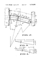
- FIG. 1 is a schematic side view illustrating apparatus constructed according to the present invention
- FIG. 2 is a schematic plan view of the apparatus
- FIGS. 3 and 4 are diagrammatic presentations illustrating geometric aspects of the invention utilized in the construction of the preferred embodiment.
- FIGS. 1 and 2 first mechanical means in the form of a dryer can 10 is illustrated.
- the dryer can has a web contact surface 12 for drying and delivering a paper web 14 in a well-known manner.
- the web 14 passes directly from the web contact surface 12 and is delivered to the next stage of the manufacturing operation, the web moving forwardly of the dryer can after it leaves the web contact surface along a predetermined path of web movement.
- paper web 14 passes about a roll 16 of conventional construction and over another roll 18 which may for example be the initial roll of a calendar, etc.
- the apparatus of the present invention may be employed in a wide variety of operational contexts other than that illustrated and that the configuration of FIGS. 1 and 2 is for illustrative purposes as it is quite typical of an operating environment where the present invention would be employed.
- first Coanda nozzle 24 Positioned adjacent to the surface 12 below the normal exit location of web 14 is a first Coanda nozzle 24.
- This nozzle is of a two-dimensional type such as that illustrated in U.S. Pat. Nos. 3,999,696 and 4,014,487 and will not be described in detail other than to state that the nozzle includes a longitudinal exit slit 26 through which pressurized gas is emitted with the foil surface of the nozzle directing the emitted gas in a forward direction so that it, and any ambient gases entrained thereby, will flow along a first bottom wall 28 extending from the nozzle as shown in the aforesaid patents. Side walls 29 and 31 extend upwardly from the edges of wall 28 to form an open-topped trough or chute.
- a tail will be formed by the operator as described in the afore-mentioned two patents and such tail will be entrained by the gases flowing along wall element 28 when placed into engagement therewith.
- the chute formed by walls 28, 29 and 31 is preferably pivoted at the web exit end thereof, i.e. the right end as viewed in FIG. 1, so that it may be swung from the illustrated phantom line position to the solid line position, thus bringing the web (which is moving downwardly from the dryer can) into engagement with the gaseous flow initiated by nozzle 24.
- roller 18 Disposed at the end of roller 18 is a rope 36 which forms a nip with a rope 37 entrained about a pulley 38, with the ropes forming a nip through which the web tail is to pass in the well-known manner.
- the rope nip is disposed at the extreme end of roll 18, that is, it is laterally offset from the normal path of movement of web 14. If the web were to be projected directly forwardly by the two Coanda nozzles the tail would miss the rope nip altogether and successful threading of the machine components with which the ropes are associated would not be successfully completed.
- the second Coanda nozzle is angularly disposed relative to the first Coanda nozzle at an angle ⁇ 2 .
- the angular displacements ⁇ 1 and ⁇ 2 are calculated as follows.
- the first step is to determine the true length (T L ) of the path of the web (see FIGS. 1, 3 and 4):
- the next step is to determine the offset distance O T :
- O t distance from the edge of the web to the desired predetermined location, e.g. the center line of the rope nip plus one-half of the tail width.
- tail sideways displacement is desirably made in two steps. It is first displaced by the angle ⁇ 1 , then by an angle ⁇ 2 .
- FIG. 2 summarizes design features and indicates the radius of curvature R through which the tail bends in the horizontal plane. ##EQU1##
Abstract
Description
T.sub.L = L.sub.1 + L.sub.2 (1)
O.sub.T /T.sub.L = tan β (3)
α.sub.1 < β ; α.sub.2 > β and α.sub.1 = 1/2 α.sub.2 (4)
(l.sub.1 - n) tan α.sub.1 = O.sub.1 (6)
l.sub.2 tan α.sub.2 = O.sub.2 (7)
              TABLE I
______________________________________
      Degrees   Degrees   Inches Inches Inches
Item  α.sub.1
                α.sub.2
                          L.sub.1
                                 L.sub.2
                                        R
______________________________________
1     10        20         173/8 321/2   213/4
2      21/2      5        31     461/2  1631/2
3     6         12        20     111/2  42
4     3          6         171/4 48      701/2
5     6         12        20     201/2  42
______________________________________
Claims (7)
Priority Applications (15)
| Application Number | Priority Date | Filing Date | Title |
|---|---|---|---|
| US05/853,692 US4136808A (en) | 1977-11-21 | 1977-11-21 | Web threading system |
| AT0704578A AT367117B (en) | 1977-11-21 | 1978-03-06 | DEVICE FOR GUIDING THE APPROACH OF A MOVING TRACK OF FLEXIBLE MATERIAL |
| JP10569778A JPS54116564A (en) | 1977-11-21 | 1978-08-31 | Web deflection guide apparatus |
| AU39832/78A AU519589B2 (en) | 1977-11-21 | 1978-09-13 | Web threading system |
| CA311,590A CA1069950A (en) | 1977-11-21 | 1978-09-19 | Web threading system |
| BR7806229A BR7806229A (en) | 1977-11-21 | 1978-09-21 | DEVICE AND PROCESS OF ORIENTATION OF THE TAIL OF A COIL OF FLEXIBLE MATERIAL AND COMBINATION OF MECHANICAL MEANS |
| GB7838357A GB2008546B (en) | 1977-11-21 | 1978-09-27 | Flexible web directing apparatus and method of directing flexible web |
| DE2842295A DE2842295C2 (en) | 1977-11-21 | 1978-09-28 | Device for guiding the direction of the approach of a moving web made of flexible material |
| BE191579A BE871823A (en) | 1977-11-21 | 1978-11-07 | DEVICE FOR THREADING A CONTINUOUS SHEET |
| NL7811051A NL7811051A (en) | 1977-11-21 | 1978-11-07 | ARRANGEMENT AND PROCEDURE FOR PUTTING THE END OF A MOVING JOB BETWEEN ROLES. |
| SE7811684A SE443773B (en) | 1977-11-21 | 1978-11-13 | RANGE RANGE AND DEFINITION DEVICE WITH GASFUL FLOW FROM THE COANDAMUN PIECE CONTROLING THE RANGE OF FLEXIBLE MATERIAL |
| IT29853/78A IT1102313B (en) | 1977-11-21 | 1978-11-16 | METHOD AND APPARATUS TO THREAD A TAPE OF FLEXIBLE MATERIAL |
| NO783899A NO148892C (en) | 1977-11-21 | 1978-11-20 | PROCEDURE AND APPARATUS FOR EATING A COAT OF FLEXIBLE MATERIAL. |
| FR7832810A FR2409220A1 (en) | 1977-11-21 | 1978-11-21 | DEVICE FOR THREADING A CONTINUOUS SHEET |
| FI783546A FI69039C (en) | 1977-11-21 | 1978-11-21 | ANORDNING FOER ATT STYRA FRAMAENDEN AV EN BANA |
Applications Claiming Priority (1)
| Application Number | Priority Date | Filing Date | Title |
|---|---|---|---|
| US05/853,692 US4136808A (en) | 1977-11-21 | 1977-11-21 | Web threading system |
Publications (1)
| Publication Number | Publication Date |
|---|---|
| US4136808A true US4136808A (en) | 1979-01-30 |
Family
ID=25316675
Family Applications (1)
| Application Number | Title | Priority Date | Filing Date |
|---|---|---|---|
| US05/853,692 Expired - Lifetime US4136808A (en) | 1977-11-21 | 1977-11-21 | Web threading system |
Country Status (15)
| Country | Link |
|---|---|
| US (1) | US4136808A (en) |
| JP (1) | JPS54116564A (en) |
| AT (1) | AT367117B (en) |
| AU (1) | AU519589B2 (en) |
| BE (1) | BE871823A (en) |
| BR (1) | BR7806229A (en) |
| CA (1) | CA1069950A (en) |
| DE (1) | DE2842295C2 (en) |
| FI (1) | FI69039C (en) |
| FR (1) | FR2409220A1 (en) |
| GB (1) | GB2008546B (en) |
| IT (1) | IT1102313B (en) |
| NL (1) | NL7811051A (en) |
| NO (1) | NO148892C (en) |
| SE (1) | SE443773B (en) |
Cited By (20)
| Publication number | Priority date | Publication date | Assignee | Title |
|---|---|---|---|---|
| US4186860A (en) * | 1978-10-16 | 1980-02-05 | Crown Zellerbach Corporation | Web threading system |
| US4342413A (en) * | 1981-02-05 | 1982-08-03 | Crown Zellerbach Corporation | Turning bar for moving web |
| US4726502A (en) * | 1986-07-07 | 1988-02-23 | Cryderman Gary G | Apparatus for entraining and directing a wet paper web |
| US4904344A (en) * | 1989-04-17 | 1990-02-27 | Beloit Corporation | Automatic web threading apparatus and method |
| US4923567A (en) * | 1988-01-26 | 1990-05-08 | Valmet Paper Machinery Inc | Guiding an end conduction strip of a web forwardly from a roll |
| US5188271A (en) * | 1988-12-28 | 1993-02-23 | Pitney Bowes Inc. | Segmented tape transport and moistening system |
| US5213246A (en) * | 1990-09-10 | 1993-05-25 | Roll Systems, Inc. | Paper guiding method and apparatus |
| US5308005A (en) * | 1990-12-28 | 1994-05-03 | Eastman Kodak Company | Film handling system |
| EP0723862A1 (en) * | 1995-01-25 | 1996-07-31 | Maschinenfabrik Wifag | Method and device for threading a printed web |
| US5622601A (en) * | 1995-09-19 | 1997-04-22 | Beloit Technologies, Inc. | Method and apparatus for effecting a clipped tail in a traveling paper web |
| US5635030A (en) * | 1994-03-15 | 1997-06-03 | Voith Sulzer Papiermaschinen Gmbh | Process and device for guiding a material web |
| US5820007A (en) * | 1994-11-04 | 1998-10-13 | Roll Systems, Inc. | Method and apparatus for pinless feeding of web to a utilization device |
| US5967394A (en) * | 1994-11-04 | 1999-10-19 | Roll Systems, Inc. | Method and apparatus for pinless feeding of web to a utilization device |
| US5979732A (en) * | 1994-11-04 | 1999-11-09 | Roll Systems, Inc. | Method and apparatus for pinless feeding of web to a utilization device |
| EP1002898A2 (en) * | 1998-11-18 | 2000-05-24 | PAPRIMA Industries Inc. | Directional tail transfer threading apparatus |
| US20010050300A1 (en) * | 1999-08-13 | 2001-12-13 | Voith Sulzer Papiertechnik Patent | Web handling process |
| US20040129397A1 (en) * | 2001-06-27 | 2004-07-08 | Olli Huhtala | Arrangement for threading of web in a pulp machine |
| US20080035777A1 (en) * | 2006-08-11 | 2008-02-14 | Fabio Perini S.P.A. | Device and method for feeding plies of web material |
| WO2012084380A1 (en) * | 2010-12-23 | 2012-06-28 | Voith Patent Gmbh | Device for producing and/or treating material webs |
| US10087581B2 (en) | 2015-01-14 | 2018-10-02 | TAKSO Software Ltd | Arrangement and method for tail-threading a fibrous web |
Families Citing this family (5)
| Publication number | Priority date | Publication date | Assignee | Title |
|---|---|---|---|---|
| US4371418A (en) * | 1980-12-22 | 1983-02-01 | British-American Tobacco Company Limited | Feeding web material |
| FI62695C (en) * | 1981-05-15 | 1983-02-10 | Valmet Oy | PAPER MACHINERY FOR PAPER MACHINERY AND PAPER MACHINERY |
| DE4425417C1 (en) * | 1994-07-19 | 1996-02-08 | Fischer Maschf Karl E | Automatic belt transfer device |
| DE19962731A1 (en) * | 1999-12-23 | 2001-06-28 | Voith Paper Patent Gmbh | Conveyor for transporting web of flexible material has inlet device upon which is attached separating device, and inlet device is constructed as plate which on entry end has unit for delivery of air jet onto plate |
| CN109205394B (en) * | 2018-07-21 | 2020-02-14 | 嘉兴市华昌纺织有限公司 | Automatic change weaving device |
Citations (3)
| Publication number | Priority date | Publication date | Assignee | Title |
|---|---|---|---|---|
| US3125268A (en) * | 1964-03-17 | bartholomay | ||
| US3705676A (en) * | 1970-03-16 | 1972-12-12 | Overly Inc | Air foil conveyor |
| US4043495A (en) * | 1975-03-03 | 1977-08-23 | Frank Sander | Air cushioned turn bar |
Family Cites Families (2)
| Publication number | Priority date | Publication date | Assignee | Title |
|---|---|---|---|---|
| US3999696A (en) * | 1975-05-27 | 1976-12-28 | Crown Zellerbach Corporation | Web threading system |
| US4014487A (en) * | 1976-03-31 | 1977-03-29 | Crown Zellerbach Corporation | Web threading system |
-
1977
- 1977-11-21 US US05/853,692 patent/US4136808A/en not_active Expired - Lifetime
-
1978
- 1978-03-06 AT AT0704578A patent/AT367117B/en not_active IP Right Cessation
- 1978-08-31 JP JP10569778A patent/JPS54116564A/en active Granted
- 1978-09-13 AU AU39832/78A patent/AU519589B2/en not_active Expired
- 1978-09-19 CA CA311,590A patent/CA1069950A/en not_active Expired
- 1978-09-21 BR BR7806229A patent/BR7806229A/en unknown
- 1978-09-27 GB GB7838357A patent/GB2008546B/en not_active Expired
- 1978-09-28 DE DE2842295A patent/DE2842295C2/en not_active Expired
- 1978-11-07 BE BE191579A patent/BE871823A/en not_active IP Right Cessation
- 1978-11-07 NL NL7811051A patent/NL7811051A/en not_active Application Discontinuation
- 1978-11-13 SE SE7811684A patent/SE443773B/en not_active IP Right Cessation
- 1978-11-16 IT IT29853/78A patent/IT1102313B/en active
- 1978-11-20 NO NO783899A patent/NO148892C/en unknown
- 1978-11-21 FI FI783546A patent/FI69039C/en not_active IP Right Cessation
- 1978-11-21 FR FR7832810A patent/FR2409220A1/en active Granted
Patent Citations (3)
| Publication number | Priority date | Publication date | Assignee | Title |
|---|---|---|---|---|
| US3125268A (en) * | 1964-03-17 | bartholomay | ||
| US3705676A (en) * | 1970-03-16 | 1972-12-12 | Overly Inc | Air foil conveyor |
| US4043495A (en) * | 1975-03-03 | 1977-08-23 | Frank Sander | Air cushioned turn bar |
Cited By (27)
| Publication number | Priority date | Publication date | Assignee | Title |
|---|---|---|---|---|
| US4186860A (en) * | 1978-10-16 | 1980-02-05 | Crown Zellerbach Corporation | Web threading system |
| US4342413A (en) * | 1981-02-05 | 1982-08-03 | Crown Zellerbach Corporation | Turning bar for moving web |
| US4726502A (en) * | 1986-07-07 | 1988-02-23 | Cryderman Gary G | Apparatus for entraining and directing a wet paper web |
| US4923567A (en) * | 1988-01-26 | 1990-05-08 | Valmet Paper Machinery Inc | Guiding an end conduction strip of a web forwardly from a roll |
| US5188271A (en) * | 1988-12-28 | 1993-02-23 | Pitney Bowes Inc. | Segmented tape transport and moistening system |
| US4904344A (en) * | 1989-04-17 | 1990-02-27 | Beloit Corporation | Automatic web threading apparatus and method |
| US5213246A (en) * | 1990-09-10 | 1993-05-25 | Roll Systems, Inc. | Paper guiding method and apparatus |
| USRE35844E (en) * | 1990-09-10 | 1998-07-14 | Roll Systems, Inc. | Paper guiding method and apparatus |
| US5308005A (en) * | 1990-12-28 | 1994-05-03 | Eastman Kodak Company | Film handling system |
| US5635030A (en) * | 1994-03-15 | 1997-06-03 | Voith Sulzer Papiermaschinen Gmbh | Process and device for guiding a material web |
| US5820007A (en) * | 1994-11-04 | 1998-10-13 | Roll Systems, Inc. | Method and apparatus for pinless feeding of web to a utilization device |
| US5967394A (en) * | 1994-11-04 | 1999-10-19 | Roll Systems, Inc. | Method and apparatus for pinless feeding of web to a utilization device |
| US5979732A (en) * | 1994-11-04 | 1999-11-09 | Roll Systems, Inc. | Method and apparatus for pinless feeding of web to a utilization device |
| US6056180A (en) * | 1994-11-04 | 2000-05-02 | Roll Systems, Inc. | Method and apparatus for pinless feeding of web to a utilization device |
| EP0723862A1 (en) * | 1995-01-25 | 1996-07-31 | Maschinenfabrik Wifag | Method and device for threading a printed web |
| US5622601A (en) * | 1995-09-19 | 1997-04-22 | Beloit Technologies, Inc. | Method and apparatus for effecting a clipped tail in a traveling paper web |
| EP1002898A2 (en) * | 1998-11-18 | 2000-05-24 | PAPRIMA Industries Inc. | Directional tail transfer threading apparatus |
| US6073825A (en) * | 1998-11-18 | 2000-06-13 | Paprima Industries Inc. | Directional tail transfer threading apparatus |
| EP1002898A3 (en) * | 1998-11-18 | 2003-05-02 | PAPRIMA Industries Inc. | Directional tail transfer threading apparatus |
| US6425512B2 (en) * | 1999-08-13 | 2002-07-30 | Voith Sulzer Papiertechnik Patent Gmbh | Web handling process |
| US20010050300A1 (en) * | 1999-08-13 | 2001-12-13 | Voith Sulzer Papiertechnik Patent | Web handling process |
| US20040129397A1 (en) * | 2001-06-27 | 2004-07-08 | Olli Huhtala | Arrangement for threading of web in a pulp machine |
| US7135091B2 (en) * | 2001-06-27 | 2006-11-14 | Metso Paper, Inc. | Arrangement for threading of web in a pulp machine |
| US20080035777A1 (en) * | 2006-08-11 | 2008-02-14 | Fabio Perini S.P.A. | Device and method for feeding plies of web material |
| US7938355B2 (en) | 2006-08-11 | 2011-05-10 | Fabio Perini S.P.A. | Device and method for feeding plies of web material |
| WO2012084380A1 (en) * | 2010-12-23 | 2012-06-28 | Voith Patent Gmbh | Device for producing and/or treating material webs |
| US10087581B2 (en) | 2015-01-14 | 2018-10-02 | TAKSO Software Ltd | Arrangement and method for tail-threading a fibrous web |
Also Published As
| Publication number | Publication date |
|---|---|
| GB2008546B (en) | 1982-06-09 |
| FI69039C (en) | 1985-12-31 |
| AU3983278A (en) | 1980-03-20 |
| IT1102313B (en) | 1985-10-07 |
| BR7806229A (en) | 1979-07-24 |
| SE7811684L (en) | 1979-05-22 |
| DE2842295A1 (en) | 1979-05-23 |
| FR2409220A1 (en) | 1979-06-15 |
| FI783546A (en) | 1979-05-22 |
| NO783899L (en) | 1979-05-22 |
| IT7829853A0 (en) | 1978-11-16 |
| NO148892B (en) | 1983-09-26 |
| GB2008546A (en) | 1979-06-06 |
| SE443773B (en) | 1986-03-10 |
| FI69039B (en) | 1985-08-30 |
| AT367117B (en) | 1982-06-11 |
| NO148892C (en) | 1984-01-11 |
| FR2409220B1 (en) | 1983-09-30 |
| DE2842295C2 (en) | 1984-11-15 |
| ATA704578A (en) | 1981-10-15 |
| JPS5757379B2 (en) | 1982-12-04 |
| CA1069950A (en) | 1980-01-15 |
| JPS54116564A (en) | 1979-09-10 |
| NL7811051A (en) | 1979-05-23 |
| BE871823A (en) | 1979-03-01 |
| AU519589B2 (en) | 1981-12-10 |
Similar Documents
| Publication | Publication Date | Title |
|---|---|---|
| US4136808A (en) | Web threading system | |
| US4014487A (en) | Web threading system | |
| US3999696A (en) | Web threading system | |
| CA1101899A (en) | Web threading system | |
| US4056264A (en) | Stack forming device | |
| US4182170A (en) | Device for cutting a fiber web | |
| US3243181A (en) | Sheet handling device | |
| US6474589B1 (en) | Change device of a reel-up and method for changing a roll | |
| GB2098912A (en) | Means for cutting and guiding a marginal strip of a paper web | |
| KR900700919A (en) | Curtain cloth starting method and device | |
| JPS62175375A (en) | Tail guide for paper-making machine | |
| US6290817B1 (en) | Device for conveying and guiding a lead-in strip of a web in a paper machine | |
| JPH0321463B2 (en) | ||
| US6073825A (en) | Directional tail transfer threading apparatus | |
| NL9301483A (en) | Folding device for zigzag folding a sheet. | |
| US3273886A (en) | Reverse transport for flexible sheets | |
| EP0870711A2 (en) | Method and apparatus for direct shingling of cut sheets at the cutoff knife | |
| EP1076131A2 (en) | Vacuum conveyor | |
| CA1065787A (en) | Board grouping apparatus | |
| US4691450A (en) | Method and apparatus for the removal of liquid from a running yarn | |
| EP0997419A1 (en) | Airbar for use in web processing | |
| JPS598609B2 (en) | Web Anna Isouchi | |
| FI103425B (en) | Threading apparatus and method for inserting the end of the web | |
| EP1746207A2 (en) | Stabilizing apparatus for paper webs in the course of formation | |
| EP0443646A1 (en) | Method and device for either cutting or perforating a moving web of paper |
Legal Events
| Date | Code | Title | Description |
|---|---|---|---|
| AS | Assignment |
Owner name: JAMES RIVER CORPORATION OF NEVADA, A NEVADA CORP., Free format text: CHANGE OF NAME;ASSIGNOR:CROWN ZELLERBACH CORPORATION, A CORPORATION OF NV;REEL/FRAME:007744/0737 Effective date: 19870331 Owner name: JAMES RIVER CORPORATION OF VIRGINIA, A VA CORP., V Free format text: MERGER;ASSIGNOR:JAMES RIVER CORPORATION OF NEVADA, A NV CORP.;REEL/FRAME:007629/0091 Effective date: 19880423 Owner name: JAMES RIVER CORPORATION OF VIRGINIA, A CORP. OF VI Free format text: MERGER;ASSIGNOR:JAMES RIVER CORPORATION OF NEVADA, A CORP. OF NEVADA;REEL/FRAME:007764/0852 Effective date: 19880423 Owner name: JAMES RIVER CORPORATION OF NEVADA, A CORP. OF NEVA Free format text: CHANGE OF NAME;ASSIGNOR:CROWN ZELLERBACH CORPORATION, A CORP. OF NEVADA;REEL/FRAME:007629/0093 Effective date: 19870331 |
|
| AS | Assignment |
Owner name: J.P. MORGAN DELAWARE, AS COLLATERAL AGENT, DELAWAR Free format text: SECURITY AGREEMENT;ASSIGNOR:CROWN PAPER CO.;REEL/FRAME:007722/0902 Effective date: 19950823 |