US4159595A - Installation for cultivating plants - Google Patents
Installation for cultivating plants Download PDFInfo
- Publication number
- US4159595A US4159595A US05/732,090 US73209076A US4159595A US 4159595 A US4159595 A US 4159595A US 73209076 A US73209076 A US 73209076A US 4159595 A US4159595 A US 4159595A
- Authority
- US
- United States
- Prior art keywords
- hose
- installation
- liquid
- hoses
- temperature
- Prior art date
- Legal status (The legal status is an assumption and is not a legal conclusion. Google has not performed a legal analysis and makes no representation as to the accuracy of the status listed.)
- Expired - Lifetime
Links
Images


Classifications
-
- A—HUMAN NECESSITIES
- A01—AGRICULTURE; FORESTRY; ANIMAL HUSBANDRY; HUNTING; TRAPPING; FISHING
- A01G—HORTICULTURE; CULTIVATION OF VEGETABLES, FLOWERS, RICE, FRUIT, VINES, HOPS OR SEAWEED; FORESTRY; WATERING
- A01G13/00—Protecting plants
- A01G13/02—Protective coverings for plants; Coverings for the ground; Devices for laying-out or removing coverings
- A01G13/0256—Ground coverings
-
- A—HUMAN NECESSITIES
- A01—AGRICULTURE; FORESTRY; ANIMAL HUSBANDRY; HUNTING; TRAPPING; FISHING
- A01G—HORTICULTURE; CULTIVATION OF VEGETABLES, FLOWERS, RICE, FRUIT, VINES, HOPS OR SEAWEED; FORESTRY; WATERING
- A01G9/00—Cultivation in receptacles, forcing-frames or greenhouses; Edging for beds, lawn or the like
- A01G9/24—Devices or systems for heating, ventilating, regulating temperature, illuminating, or watering, in greenhouses, forcing-frames, or the like
- A01G9/245—Conduits for heating by means of liquids, e.g. used as frame members or for soil heating
-
- Y—GENERAL TAGGING OF NEW TECHNOLOGICAL DEVELOPMENTS; GENERAL TAGGING OF CROSS-SECTIONAL TECHNOLOGIES SPANNING OVER SEVERAL SECTIONS OF THE IPC; TECHNICAL SUBJECTS COVERED BY FORMER USPC CROSS-REFERENCE ART COLLECTIONS [XRACs] AND DIGESTS
- Y02—TECHNOLOGIES OR APPLICATIONS FOR MITIGATION OR ADAPTATION AGAINST CLIMATE CHANGE
- Y02A—TECHNOLOGIES FOR ADAPTATION TO CLIMATE CHANGE
- Y02A40/00—Adaptation technologies in agriculture, forestry, livestock or agroalimentary production
- Y02A40/10—Adaptation technologies in agriculture, forestry, livestock or agroalimentary production in agriculture
- Y02A40/25—Greenhouse technology, e.g. cooling systems therefor
Abstract
An installation for cultivating plants on a soil, characterized in that it comprises at least one heat-exchanger, each of said exchangers being constituted by an elongated flat flexible hose with a then wall resting on the soil, and feed means for circulating liquid of a preselected regulated temperature through each of said hoses.
Description
This is a continuation, of application Ser. No. 539,106 filed Jan. 7, 1975 now abandoned.
The present invention relates to an installation for cultivating plants on a soil.
More specifically, the invention relates to an installation adapted to heat (or, contingently cool) the soil in order to promote the plant cultivation to be carried out therein. To that end, water at relatively low temperature is caused to flow in tubes, or hoses, resting on the soil.
Up to this day when sunlight does not provide sufficient heat, the heating operation has been carried out either by means of pulsed hot air, or through radiation of means of very hot water flowing in small diameter overhead conduits. Alternatively, conduction, by means of very hot water flowing in small diameter conduits sunk in the ground, has also been used. In the latter case, the high thermal inertia does not permit easy adjustment to meet abrupt climatic changes.
The invention directly relates to an installation for cultivating plants which can operate with water at a relatively low temperature flowing in hoses, which is more easily handled and less costly than the operations mentioned above.
The present installation for cultivating plants on a soil is characterized in that it comprises at least one heat-exchanger, each of said exchangers being constituted by an elongated flat flexible hose with a thin wall resting on the soil, and feed-means for circulating liquid of a preselected regulated temperature through each of said hoses.
According to an embodiment, the installation is characterized in that the liquid provided by said feed-means is water at an average temperature of less than 45° C.
Preferably, that water has a static head of less than 10 cm of water.
According to a possible embodiment, said feed-means are constituted by a heat-pump adapted to deliver water at a temperature of from 25° to 45° C. achieved by means of calories withdrawn from water at a temperature of from 4° to 25° C. feeding the evaporation associated to said pump.
The heat-pump evaporator can be fed either with water expelled by an industrial plant or with the water from a ground water reservoir.
Alternatively the installation can be fed directly with hot water expelled by an industrial plant.
According to another embodiment, said hoses are connected, at one end to a first manifold which, is connected to the feed-means, and at the other end to a second manifold which is connected to a return line.
According to a another embodiment, the hoses are pin-shaped and said two manifolds are located side-by-side.
The invention is also concerned with applying the installation to cultivation with mulching.
The invention also relates to applying the installation to the conditioning of green-houses where the invention can include means for interrupting the flow of hot water in the hoses as soon as the green-houses have reached a sufficient temperature, and means for circulating cool water in said hoses in order to cool the green-house temperature during sunny periods.
The invention will be more clearly understood from the following description given hereunder of various embodiments, with reference to the accompanying drawing, in which:
FIG. 1 is a side view, partially in section, of the exchanger according to the invention;
FIG. 2 is a cross-section of the exchanger hose;
FIG. 3 is a variant of FIG. 2;
FIG. 4 shows another variant, adapted to permit mulching and planting out;
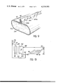
FIG. 5 is a perspective view, partially in cross-section of a mattress-like hose;
FIGS. 6 and 7 are perspective views showing the feeding of the hoses by means of manifolds;
FIG. 8 is the diagram of another embodiment of the feed-means;
FIG. 9 is a sectional view of another embodiment of the hoses;
FIG. 10 shows means for circulating cold as well as hot fluids in the hoses.
In FIG. 1, exchanger 1 comprises a hose 2 connected at its upstream end to a constant level feed-tank 3 by means of an adapter 4a. The hose is terminated at its downstream and by an adapter 4b with loss of head. Along hose 2 circulates a hot-fluid 8.
Hose 2 (FIG. 2) is flat, its width l being much greater than its thickness e. The thin walls 2a define an inner passage 2b, the cross-section of which is flat, too.
The tube provides only one passage 2b and, in spite of its wall being thin, it can be trampled or punctured without being severely damaged; a puncture therein will simply generate a slight seeping, not detrimental to the exchanger flow-rate.
In view of the low pressure of the hot-fluid film flowing in the hose, the passage 2b of the latter maintains its flat shape.
With a view to increasing the exchanger area without making it vulnerable to possible shocks, the invention provides the use of a flexible hose 5, with longitudinal partitions (FIG. 3) so as to form parallel conduits 5a of very small diameter.
The upstream adapter 4a permits to connect hose 2 to tank 3, whereas downstream adapter 4b is so designed as to raise the hot-fluid jet 8 above the ground level.
For cultivation with mulching (hoses of black plastics), it is possible to provide hoses ensuring both mulching and the flow of water. To that end (FIG. 4), holes, or ports, so made through the opposed walls 2a of hose 2 are connected by means of circular welds 12 maintaining inner passage 2b tight. Ports 10 are evenly distributed over the whole surface of hose 2, thus allowing the planting out of seedlings through the latter. For such an application, the various hoses should cover at least 50% of the ground surface. Similar holes (not shown) with welded edges can be applied to partitioned hose 5.
In order to facilitate the manufacture of the mulching-hoses, viz, the hoses with holes made through their walls and connected edge-to-edge by means of welds, it is possible to form said holes as simple cut-outs substantially converging to the center of the weld.
A method for manufacturing such mulching-hoses consists in making the edge-to-edge welds of the opposed walls of the hoses and of the cut-outs simultaneously by applying against the hose at least one tool comprising a heated crown, the inside of which is provided with knives.
The exchanger according to the invention operates with low temperature differentials, viz, at an average fluid temperature lower than 45° C. While the most convenient hot fluid to be used is, of course, water, there would be however no objection to use another fluid, e.g., oil, provided it may be recovered.
Should the hot fluid used be water, a 10 cm head in the tank and a proper adjustment of the loss-of-head of downstream adapter 4b would be sufficient for providing an even flow of film B.
A good thermal efficiency of the exchanger is achieved in view of the large area of the contact surface between the hose and the ground, and the hose flat shape makes it more easily wound on a winding-drum and permits to store it more conveniently.
FIG. 5 shows another embodiment of hoses 2 consisting in mattress-like hoses, viz, hoses the opposite walls of which are connected at a plurality of places along their lengths. Such connection between the two walls can be in the form of dots, circles, rectilinear segments, either aligned, or staggered or in herring-bone pattern. Such an arrangement provides many advantages:
it renders the hose more stable by preventing it from coiling and, thus, damaging crops;
it reduces the thickness of the hose in operation, while maintaining the same flow-rate;
it permits to increase the pressure which, therefore, can be higher than 10 cm of water, since the hoses can not swell and become cylindrical to the point of rolling on the ground. Such a pressure increase permits to use hoses of greater lengths;
it induces turbulent movements promoting the transfer of heat;
it ensures a fair mixture of water streams and, therefore, evenly distributes the temperature of water across the hose.
FIG. 5 shows a hose made mattress-like by means of rectilinear segments 14 arranged in herring-bone pattern.
In the hose water-feed such as shown in FIG. 1, the coolant liquid is not recovered, which is a nuisance if the liquid used is relatively expensive. Such an arrangement is also a nuisance should the liquid used be water and the installation according to the invention erected in a barren area.
FIGS. 6 and 7 show two embodiments adapted to re-cycle the liquid after it has flowed in the hoses.
According to the embodiment of FIG. 6, the hoses 2 are mounted in parallel between an upstream manifold 16 (feed) and a downstream manifold 18 (recycling). Each adapter 4a is connected to manifold 16, and each adapter 4b to manifold 18. These manifolds are advantageously rigid conduits. Manifold 16 is connected to the hot-water feed-source. Manifold 18 permits to re-cycle water (or any other liquid) once it has flowed in hoses 2, while ensuring the loss-of-head. In this instance, the nature of the hot water source will be explained later on.
Instead of being rectilinear, the hoses can have the shape of hair-pins, as shown in FIG. 7. Such a shape can also be obtaned, as in FIG. 7, by associating two half-hoses 2', 2", these two half-hoses being connected at one end thereof by a bent conduit 20.
Adapter 4a of half-hose 2' is connected to manifold 16 and adapter 4b of half-hose 2" is connected to manifold 18, these two manifold being mounted side by side.
If the installation according to the invention is located in a green-house with but one access-door, the installation can clear that door without having to disconnect the adapters. To clear the ground, one has merely to coil the hoses.
FIG. 8 illustrates a specially interesting feed-mode for the installation according to he invention by using a heat-pump.
The fluid is heated by means of a heat-pump feeding the first manifold at a temperature of from 25° to 45° C., by using the calories withdrawn from water at a temperature of from 4° to 25° C. serving to feed the evaporator of said pump.
The method permits to resort to every natural and industrial means, so as to optimize the heat-pump efficiency.
Thus, the pump evaporator can be fed either with water extracted from a phreatic sheet, or with tepid water expelled by an industrial plant.
In FIG. 8 is shown diagrammatically a heat-pump 21, the outlet of which is connected to manifold 16 through conduit 22, while its inlet is connected to manifold 18 through conduit 24.
In the spring and in the summer, the heat-exchanger can also be used, in certain hot countries, for air-conditioning. Indeed, in such hot countries, plants have to be protected against too much heat and it is therefore necessary to lower the temperature of their environment so as to allow their growth. On the other hand, in such hot countries, very hot days are followed by cool nights, and such temperature changes are detrimental to an economical exploitation.
According to a modified embodiment, the installation according to the invention are heated in the night and cooled in the day-time, means being provided for circulating in the hoses cold fluid in the day-time and hot fluid in the night. This is what is shown in FIG. 10.
For heating, evaporator 28 of heat-pump 26 is fed from the water-source of phreatic sheet 29, through three-way valve 30 and conduit 31. Three-way valve 31 permits to feed manifold 16 by means of heated-water conduit 22. Three-way valve 35 permits tepid water from manifold 18 to return to the condenser of heat-pump 21, through conduit 24.
For cooling purposes, the three valves 30, 34 and 35 are set to their other position. Manifold 16 is fed with cool water from conduit 29 via conduit 33. Manifold 18 is vented to the outside (36) through valve 35.
Abrupt temperature changes can also occur in the same day. The thermal inertia of the green-houses is relatively low, which results in abrupt temperature decreases and increases within a relatively short time. The invention permits to render temperature as even as possible in green-houses.
Water is known as having a high thermal inertia so that it is therefore possible, merely by causing water to flow in the hoses, to maintain plants in the green-houses at substantially constant temperatures. Should the thus-obtained inertia prove insufficient, water (e.g., a pool) might be kept in store for increasing it.
When the installation according to the invention is fed directly with hot industrial waters, without intermediate heat-pumps, a possible embodiment of the invention consists in providing a pressurized heat-exchanger between the hot industrial waters and the fluid flowing in the hoses. Such an embodiment separates the two fluids efficiently and prevents any penetration of industrial waters into the green-house heating fluid.
In view of the small temperature difference between the fluid flowing in the hoses and the ground on which they are laid, these hoses should cover a reltively important portion of the ground. According to a preferred solution, at least half the ground area is covered by the hoses.
In some cases, a partial de-gassing of the water flowing in the hoses was observed. This leads to the formation of gas-bubbles hitting against the hose upper wall.
While thermal exchanges between water and the soil are not modified, however exchanges between water and air are altered, which is a real nuisance when hoses are used, e.g., for heating a green-house.
As a remedy to that drawback, the hoses can be given the shape shown in FIG. 9. The upper portion of thin wall 2a is modified so as to form a bead, or flange, 50 defining a conduit 52 for the passage of gases, said conduit being parallel with passage 2b; bead 50 is obtained, e.g., by means of weld-points such as 54a, 54b.
The gas-bubbles formed gather in conduit 52 after having passed through gaps 56 between successive weld-points.
Claims (12)
1. An installation for regulating the temperature of soil for cultivating plants, comprising:
(a) a plurality of elongated hoses arranged in parallel and placed on the surface of the soil;
(b) each hose being formed of a non-self-supporting thin wall material defining an inner passage which can carry liquid therethrough so that when the hose is filled with liquid the hose will expand and lay flat with its width greater than its height and effectively regulate the temperature of the soil by transmitting the liquid temperature through the thin wall to the soil;
(c) means for preventing the hose from rolling and creating turbulence when liquid is circulated through the hose including said thin wall material forming upper and lower wall portions which are connected to each other at a plurality of places spaced apart along the length of said hose;
(d) circulation means for circulating said liquid from one end to the other through each of said hoses at a preselected regulated temperature in an amount sufficient to occupy substantially the entire inner passage of each hose; and
(e) temperature regulation means for regulating the temperature of said liquid.
2. The installation of claim 1, wherein the plurality of places which connect the upper and lower wall portions are arranged in a herring-bone pattern.
3. The installation of claim 1, further comprising:
(a) an input adapter at the input end of each hose and an output adapter at the output end of said hose to create a loss of head in liquid flowing through the hose; and
(b) feed means for feeding the hose at its input end liquid at a preselected regulated temperature in an amount sufficient to occupy substantially the entire inner passage of the hose.
4. An installation according to claim 1, wherein said hoses are connected at one end to a first manifold connected to said circulation means and at the other end to a second manifold.
5. An installation according to claim 4, wherein said hoses are arranged in the form of U-shaped hair-pins and both said manifolds are mounted side-by-side.
6. The installation of claim 1, wherein each said hose includes openings along its length extending through the height of the hose and exposing a surface of the soil for placement of plants therein, said openings being located at the plurality of places where the upper and lower wall portions are connected to each other, said openings being isolated from the inner passage of said hose by means of contact points which provide a water-tight connection between the upper and lower wall portions formed by said thin wall material.
7. The installation of claim 6, wherein said contact points for said openings are edge-to-edge welds joining the upper and lower wall portions to form a circular welded edge and wherein the opening for placement of said plant is formed within said circular welded edge.
8. An installation for regulating the termperature of soil for cultivating plants, comprising:
(a) a plurality of elongated hoses arranged in parallel and placed on the surface of the soil;
(b) each hose formed of a non-self-supporting thin wall material defining an inner passage which can carry liquid therethrough so that when the hose is filled with liquid the hose will expand and lay flat with its width greater than its height and effectively regulate the temperature of the soil by transmitting the liquid temperature through the thin wall to the soil;
(c) said thin wall material also forming an upper wall portion comprising a hollow bead which defines a conduit parallel to, and separated from, but communicating with the remainder of the base for removing gas bubbles formed in the base, by means of a plurality of contact points spaced apart along the length of said hose;
(d) circulation means for circulating said liquid from one end to the other through each of said hoses at a preselected regulated temperature in an amount sufficient to occupy substantially the entire inner passage of each hose; and
(e) temperature regulation means for regulating the temperature of said liquid.
9. The installation of claim 8, wherein the contact points are evenly distributed along the length of the hose.
10. The installation of claim 1, wherein said hoses are connected at one end to a first manifold connected to said circulation means and at the other end to a second manifold.
11. The installation of claim 10, wherein said hoses are arranged in the form of U-shaped hair-pins and both said manifolds are mounted side-by-side.
12. The installation of claim 8, further comprising:
(a) an input adapter at the input end of each hose and an output adapter at the output end of said hose adapted to create a loss of head in liquid flowing through the hose; and
(b) feed means for feeding the hose at its input end liquid at a preselected regulated temperature in an amount sufficient to occupy substantially the entire inner passage of the hose.
Applications Claiming Priority (1)
| Application Number | Priority Date | Filing Date | Title |
|---|---|---|---|
| US53910675A | 1975-01-07 | 1975-01-07 |
Related Parent Applications (1)
| Application Number | Title | Priority Date | Filing Date |
|---|---|---|---|
| US53910675A Continuation | 1975-01-07 | 1975-01-07 |
Publications (1)
| Publication Number | Publication Date |
|---|---|
| US4159595A true US4159595A (en) | 1979-07-03 |
Family
ID=24149805
Family Applications (1)
| Application Number | Title | Priority Date | Filing Date |
|---|---|---|---|
| US05/732,090 Expired - Lifetime US4159595A (en) | 1975-01-07 | 1976-10-13 | Installation for cultivating plants |
Country Status (1)
| Country | Link |
|---|---|
| US (1) | US4159595A (en) |
Cited By (11)
| Publication number | Priority date | Publication date | Assignee | Title |
|---|---|---|---|---|
| US4411101A (en) * | 1981-08-17 | 1983-10-25 | Springer Edward A | Apparatus and method for heating the root zone of plants |
| US4516721A (en) * | 1981-03-16 | 1985-05-14 | Karsten Laing | Pressureless large-area heating system |
| US4577435A (en) * | 1981-08-17 | 1986-03-25 | Springer Edward A | Micro-climate temperature control apparatus |
| US4646818A (en) * | 1984-06-28 | 1987-03-03 | Ervin Jr Essie | Heated mats for melting snow and ice from outdoor surfaces |
| US6293048B1 (en) | 1999-06-07 | 2001-09-25 | Clay Boulter | Hydroponic feeder and cooler |
| WO2002085103A1 (en) | 2001-04-19 | 2002-10-31 | Clayton Boulter | Hydroponic feeder and cooler |
| US6751972B1 (en) | 2002-11-18 | 2004-06-22 | Curtis A. Jungwirth | Apparatus for simultaneous heating cooling and humidity removal |
| US20050223638A1 (en) * | 2004-03-01 | 2005-10-13 | Moren Douglas L | Hot water apparatus and method for sustainable agriculture |
| US6955189B1 (en) * | 2003-12-19 | 2005-10-18 | Weyker Rich J | Garden hose assembly |
| WO2012074519A1 (en) * | 2010-12-01 | 2012-06-07 | Aquatherm Industries, Inc. | Process for controlling the temperature of a horticultural product |
| US11019774B2 (en) | 2015-05-15 | 2021-06-01 | Naturedyne Inc. | Plant cultivation device |
Citations (15)
| Publication number | Priority date | Publication date | Assignee | Title |
|---|---|---|---|---|
| US806901A (en) * | 1905-03-22 | 1905-12-12 | J m taylor | Irrigating system. |
| US1260914A (en) * | 1917-02-17 | 1918-03-26 | Rudolph D Kline | Method of forcing plants. |
| US1374416A (en) * | 1918-07-11 | 1921-04-12 | Wilde Poul | Plant for warming and moistening the soil-surface |
| DE585727C (en) * | 1932-01-23 | 1933-10-09 | Edmund Lesch A | System for heating and moistening outdoor crops |
| DK91350C (en) * | 1958-11-29 | 1961-07-17 | Poul Viggo Villiam Madsen | Irrigation hose for use in irrigating transplanted plants and similar plants in rows. |
| US3166458A (en) * | 1961-08-24 | 1965-01-19 | Union Carbide Corp | Large area sheet sealing |
| US3205619A (en) * | 1963-11-01 | 1965-09-14 | Eastman Kodak Co | Irrigating mulching sheet |
| US3206892A (en) * | 1960-05-24 | 1965-09-21 | Dow Chemical Co | Collapsible cold frame |
| US3362106A (en) * | 1965-12-13 | 1968-01-09 | John E. Goldring | Seed package and farming methods |
| US3470943A (en) * | 1967-04-21 | 1969-10-07 | Allen T Van Huisen | Geothermal exchange system |
| US3727345A (en) * | 1970-10-28 | 1973-04-17 | N Smith | Method of protecting plants and stimulating their growth |
| US3833013A (en) * | 1972-04-06 | 1974-09-03 | Baxter Laboratories Inc | Self-valving fluid reservoir and bubble trap |
| US3863710A (en) * | 1972-12-11 | 1975-02-04 | Richard M Masters | Heat exchange system |
| US3989572A (en) * | 1975-12-15 | 1976-11-02 | Standard Oil Company (Indiana) | Method of making irrigation conduits |
| US3993122A (en) * | 1971-08-27 | 1976-11-23 | Granges Essem Aktiebolag | Steps, stairs and the like |
-
1976
- 1976-10-13 US US05/732,090 patent/US4159595A/en not_active Expired - Lifetime
Patent Citations (15)
| Publication number | Priority date | Publication date | Assignee | Title |
|---|---|---|---|---|
| US806901A (en) * | 1905-03-22 | 1905-12-12 | J m taylor | Irrigating system. |
| US1260914A (en) * | 1917-02-17 | 1918-03-26 | Rudolph D Kline | Method of forcing plants. |
| US1374416A (en) * | 1918-07-11 | 1921-04-12 | Wilde Poul | Plant for warming and moistening the soil-surface |
| DE585727C (en) * | 1932-01-23 | 1933-10-09 | Edmund Lesch A | System for heating and moistening outdoor crops |
| DK91350C (en) * | 1958-11-29 | 1961-07-17 | Poul Viggo Villiam Madsen | Irrigation hose for use in irrigating transplanted plants and similar plants in rows. |
| US3206892A (en) * | 1960-05-24 | 1965-09-21 | Dow Chemical Co | Collapsible cold frame |
| US3166458A (en) * | 1961-08-24 | 1965-01-19 | Union Carbide Corp | Large area sheet sealing |
| US3205619A (en) * | 1963-11-01 | 1965-09-14 | Eastman Kodak Co | Irrigating mulching sheet |
| US3362106A (en) * | 1965-12-13 | 1968-01-09 | John E. Goldring | Seed package and farming methods |
| US3470943A (en) * | 1967-04-21 | 1969-10-07 | Allen T Van Huisen | Geothermal exchange system |
| US3727345A (en) * | 1970-10-28 | 1973-04-17 | N Smith | Method of protecting plants and stimulating their growth |
| US3993122A (en) * | 1971-08-27 | 1976-11-23 | Granges Essem Aktiebolag | Steps, stairs and the like |
| US3833013A (en) * | 1972-04-06 | 1974-09-03 | Baxter Laboratories Inc | Self-valving fluid reservoir and bubble trap |
| US3863710A (en) * | 1972-12-11 | 1975-02-04 | Richard M Masters | Heat exchange system |
| US3989572A (en) * | 1975-12-15 | 1976-11-02 | Standard Oil Company (Indiana) | Method of making irrigation conduits |
Cited By (11)
| Publication number | Priority date | Publication date | Assignee | Title |
|---|---|---|---|---|
| US4516721A (en) * | 1981-03-16 | 1985-05-14 | Karsten Laing | Pressureless large-area heating system |
| US4411101A (en) * | 1981-08-17 | 1983-10-25 | Springer Edward A | Apparatus and method for heating the root zone of plants |
| US4577435A (en) * | 1981-08-17 | 1986-03-25 | Springer Edward A | Micro-climate temperature control apparatus |
| US4646818A (en) * | 1984-06-28 | 1987-03-03 | Ervin Jr Essie | Heated mats for melting snow and ice from outdoor surfaces |
| US6293048B1 (en) | 1999-06-07 | 2001-09-25 | Clay Boulter | Hydroponic feeder and cooler |
| WO2002085103A1 (en) | 2001-04-19 | 2002-10-31 | Clayton Boulter | Hydroponic feeder and cooler |
| US6751972B1 (en) | 2002-11-18 | 2004-06-22 | Curtis A. Jungwirth | Apparatus for simultaneous heating cooling and humidity removal |
| US6955189B1 (en) * | 2003-12-19 | 2005-10-18 | Weyker Rich J | Garden hose assembly |
| US20050223638A1 (en) * | 2004-03-01 | 2005-10-13 | Moren Douglas L | Hot water apparatus and method for sustainable agriculture |
| WO2012074519A1 (en) * | 2010-12-01 | 2012-06-07 | Aquatherm Industries, Inc. | Process for controlling the temperature of a horticultural product |
| US11019774B2 (en) | 2015-05-15 | 2021-06-01 | Naturedyne Inc. | Plant cultivation device |
Similar Documents
| Publication | Publication Date | Title |
|---|---|---|
| US5368092A (en) | Apparatus and method for controlling temperature of a turf field | |
| US4159595A (en) | Installation for cultivating plants | |
| US5306317A (en) | Device and method for preserving putting green on a golf course | |
| US4348135A (en) | Draining, irrigating and aeration of soil and heating or cooling of soil | |
| US4565242A (en) | Heat accumulating material enclosing container and heat accumulating apparatus | |
| RU2651276C1 (en) | Soil heating device | |
| CN107072155B (en) | Heat delivery system and method | |
| US4495723A (en) | Method of preventing frost damage of vegetation | |
| US4388966A (en) | Buried heat exchanger | |
| Islamovich | The Soil of The Seedlings in Greenhouses Heating by Geothermal Energy | |
| DE2501796C2 (en) | ||
| KR100672778B1 (en) | A heat exchange synthetic resins for agricultule | |
| US5878807A (en) | Fluid channeling unit | |
| WO2012074519A1 (en) | Process for controlling the temperature of a horticultural product | |
| JP6831974B2 (en) | Growth assistance device and plant growth device | |
| JP6259424B2 (en) | Air conditioning equipment for house for plant cultivation | |
| JP4615783B2 (en) | Method for arranging underground pipes in ground temperature control system | |
| JP6814425B2 (en) | Growth assistance device and plant growth device | |
| RU2110171C1 (en) | Apparatus for stabilization of temperature mode in greenhouse | |
| JP2017148020A (en) | Raising aid device and plant growing device | |
| KR100615044B1 (en) | hot-water heating device for green house | |
| US5954129A (en) | Flow control unit | |
| CN209861795U (en) | Seedling bed heating system | |
| KR102378163B1 (en) | Energy-saving house crop cultivation apparatus by air conditioning system and house crop cultivation method thereof | |
| DE3501575A1 (en) | Device for heating hothouses |