US4189052A - Stack and nest container - Google Patents
Stack and nest container Download PDFInfo
- Publication number
- US4189052A US4189052A US05/892,795 US89279578A US4189052A US 4189052 A US4189052 A US 4189052A US 89279578 A US89279578 A US 89279578A US 4189052 A US4189052 A US 4189052A
- Authority
- US
- United States
- Prior art keywords
- container
- stacking
- nesting
- post
- foot
- Prior art date
- Legal status (The legal status is an assumption and is not a legal conclusion. Google has not performed a legal analysis and makes no representation as to the accuracy of the status listed.)
- Expired - Lifetime
Links
- 230000000284 resting effect Effects 0.000 claims abstract description 8
- 239000003381 stabilizer Substances 0.000 description 15
- 239000000463 material Substances 0.000 description 3
- 238000010276 construction Methods 0.000 description 2
- 235000015173 baked goods and baking mixes Nutrition 0.000 description 1
- 235000012787 bread loaves Nutrition 0.000 description 1
- 229920001903 high density polyethylene Polymers 0.000 description 1
- 239000004700 high-density polyethylene Substances 0.000 description 1
- 230000002401 inhibitory effect Effects 0.000 description 1
- 239000010410 layer Substances 0.000 description 1
- 230000004048 modification Effects 0.000 description 1
- 238000012986 modification Methods 0.000 description 1
- 239000004033 plastic Substances 0.000 description 1
- 229920003023 plastic Polymers 0.000 description 1
- 239000002356 single layer Substances 0.000 description 1
- 239000007787 solid Substances 0.000 description 1
- 239000012815 thermoplastic material Substances 0.000 description 1
Images


Classifications
-
- B—PERFORMING OPERATIONS; TRANSPORTING
- B65—CONVEYING; PACKING; STORING; HANDLING THIN OR FILAMENTARY MATERIAL
- B65D—CONTAINERS FOR STORAGE OR TRANSPORT OF ARTICLES OR MATERIALS, e.g. BAGS, BARRELS, BOTTLES, BOXES, CANS, CARTONS, CRATES, DRUMS, JARS, TANKS, HOPPERS, FORWARDING CONTAINERS; ACCESSORIES, CLOSURES, OR FITTINGS THEREFOR; PACKAGING ELEMENTS; PACKAGES
- B65D21/00—Nestable, stackable or joinable containers; Containers of variable capacity
- B65D21/02—Containers specially shaped, or provided with fittings or attachments, to facilitate nesting, stacking, or joining together
- B65D21/04—Open-ended containers shaped to be nested when empty and to be superposed when full
- B65D21/041—Identical multi-level containers, i.e. having at least three levels
Definitions
- This invention relates to a stack and partial nest container.
- Stack and partial nest containers are known in the art. In general such containers are constructed so that an upper container will stack on or partially nest within a like lower container depending upon the orientation of the upper container with respect to the lower container.
- stack and partial nest containers are particularly useful, for example, in the storage and transportation of bakery products where it is often desirable to handle trays containing a single layer of a dense product of relatively low dimensions, such as small pound cakes, etc., as well as trays containing several layers less dense materials, such as bread loaves, etc.
- the partial stacking feature allows one to stack a tray upon a partially filled tray in a lower position thus with a suitably constructed stack and partial nest container it is possible using the one type of container to stack completely filled and partially filled containers in a much smaller area.
- An object of the present invention is to provide a stack and partial nest container constructed such that when it contains another like container in the partial nest position its endwalls will have much greater resistance to outward flexing than prior art stack and partial nest containers similarly nested.
- Another object of an embodiment of the present invention is to provide a stack and partial nest container constructed such that when it has another compatible container stacked thereon parts of the inventive container will serve to inhibit shifting of the upper container from sidewall to sidewall relative to the inventive lower container.
- Still another object of an embodiment of the present invention is to provide a stack and partial nest container constructed such that when it has another compatible container partially nested therein parts of the inventive container will serve to inhibit shifting of the upper container from sidewall to sidewall relative to the lower container.
- a stack and partial nest container comprising a generally horizontally disposed generally rectangular bottom and opposed first and second endwalls projecting upwardly from first and second opposed ends of said bottom.
- the first and second endwalls comprises a plurality of spaced apart generally vertical columns. The columns and spaces therebetween in one of said first and second opposed endwalls are arranged with respect to columns and spacing therebetween of the other of said first and second endwalls so that another like container, when reversely oriented with respect to said container, will fit inside said container in a partial nest position, i.e., in a position somewhere between the stacked position and the completely nested position where the bottom of the upper container rests upon the upper surface of the bottom of the lower container.
- each endwall each contain on upper surfaces thereof a stacking post and on lower surface thereof a stacking foot adapted such that when said container is stacked upon another identically oriented identical container the stacking foot of the upper container will fit over the outer surface of the stacking post of the corresponding column of the lower container such that said stacking posts of said lower container and said stacking feet of said upper containers cooperate to limit any outward flexing of the endwalls of the lower container due to weight resting upon the upper container.
- Each endwall of said container further comprises at least two nesting posts and at least two nesting feet located in the spaces between said columns in such a manner that when an identical container is rotated 180 degrees and partially nested therein a stacking foot of the upper container will fit over the outer surface of each nesting post of the lower container such that said stacking feet and said nesting posts cooperate to limit outward flexing of the endwalls of the lower container and each partial nesting foot of the upper container will fit over the outer surface a stacking post of the lower container such that said stacking foot and said nesting posts cooperate to limit outward flexing of the endwalls of the lower container due to weight resting upon the upper container.
- one column on each endwall contains a first stabilizer post adapted for contact with one side of the lower end of the corresponding column of an identically oriented identical container stacked thereon so as to inhibit shifting of the upper tray from sidewall to sidewall relative to the lower inventive tray.
- each endwall also includes a second stabilizer post adapted for contact with one side of one of the columns of a reversely oriented identical container partially nested therein so as to inhibit shifting of the upper container from sidewall to sidewall relative to the lower inventive tray.
- first stabilizer post of each endwall of the inventive container is also adapted for contact with the side of said endwall that is opposite said second stabilizer post of a reversely oriented identical container partially nested therein so as to assist said second stabilizer post of said inventive container in inhibiting shifting of the upper container from sidewall to sidewall relative to the lower inventive tray.
- the at least one stacking post and at least one stacking foot on each endwall is constructed such that when two such containers are placed in the stacked position said stacking post of the lower container and said stacking foot of the upper container cooperate to limit the extent that the upper container can shift from sidewall to sidewall relative to the lower container.
- the endwalls are constructed such that when such a container is placed in an identical container in the partial nest position at least one nesting foot of the upper tray and at least one stacking post of the lower tray of each endwall and at least one nesting post and at least one stacking foot of each endwall cooperate to limit the extent that the upper container can shift from sidewall to sidewall relative to the lower container.
- the container of this invention can, and preferably does, contain one or two sidewalls each extending upwardly from a respective one of the other two opposed sides of the bottom of the container.
- the only requirement on the construction of these additional sidewalls is that they not prevent the stacking and partial nesting capability provided by the endwalls as described above.
- the container contains two opposed sidewalls which allow one to nest such container upon the sidewalls of a lower such container oriented 90° relative thereto.
- the two opposed sidewalls permit a second container to nest within the first container sufficiently far enough that when a third container oriented the same as the lowermost container is placed upon the second container it will stack upon the first, i.e., lowermost, container as though the second container were not even present.
- the container of the present invention may be made of any suitable material, preferably the tray is made of the plastics conventionally used in making bakery trays and the like.
- the container is molded from a single homogenous mass of thermoplastic material such as high density polyethylene.
- the bottom of the present container can be of any suitable form. While the bottom can comprise a solid plane sheet of material it is preferred that the bottom contain perforations. In an especially preferred embodiment the bottom comprises a gridwork of the type generally employed in bakery trays and the like.
- FIG. 1 is a top perspective view of a specific bakery tray which is a presently preferred embodiment of this invention.
- FIG. 2 is a top perspective of the tray of FIG. 1 rotated 180° from the position shown in FIG. 1;
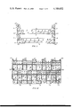
- FIG. 3, is a top plan view of the tray of FIG. 1;
- FIG. 4 is a side elevation view of the one sidewall of the tray of FIG. 1;
- FIG. 5 is a side elevation view of the other sidewall of the tray of FIG. 1;
- FIG. 6, is a cross-sectional view taken along line 6--6 of FIG. 4;
- FIG. 7 is a cross-sectional view taken along line 7--7 of FIG. 5;
- FIG. 8 is a cross-sectional view taken along line 8--8 of FIG. 3;
- FIG. 9 is a cross-sectional view taken along line 9--9 of FIG. 3;
- FIG. 10 is an end elevation view showing two trays of the type shown in FIG. 1 in the identially oriented stack relationship;
- FIG. 11 is a side elevation view showing two trays of the type shown in FIG. 1 in the identically oriented stacked relationship;
- FIG. 12 is an end elevation view showing two trays of the type shown in FIG. 1 oriented 180° relative to each other in the partial nested relationship;
- FIG. 13 is a side elevation view showing two trays of the type in FIG. 1 oriented 180° relative to each other in the partial nested relationship;
- FIG. 14 is a end elevation view of a tray as shown in FIG. 1 containing an idential tray in the 90° nesting relationship;
- FIG. 15 is a side elevation view of a tray as shown in FIG. 1 containing an identical tray in the 90° nesting relationship.
- the container illustrated in FIG. 1 is a generally rectangular container having two opposed endwalls 2 and 4, a sidewall 6, and a sidewall 8, extending upward from respective sides of a generally rectangular bottom 10.
- the bottom 10 comprises a gridwork.
- the sidewall 6 and the sidewall 8 are constructed so as to permit one to nest on such container inside another such container oriented 180° relative thereto.
- Each of the endwalls 2 and 4 comprises five spaced apart generally vertical columns 12.
- the columns 12 and the spaces therebetween in endwall 2 are arranged with respect to the columns and spaces therebetween of endwall 4 so that another like container, when reversely oriented with respect to said container, will fit inside said container in a partial nest position. This is achieved in the container illustrated by placing the respective columns and spaces of each endwall 2 and 4 directly opposite each other.
- Each column 12 of each endwall 2 and 4 of the container has upon its upper surface a stacking post 14 and on its lower surface a stacking foot 16.
- the stacking foot 16 is adapted to fit down the outer surface of the stacking post 14 of a corresponding column of another identically oriented identical container upon which said container is stacked, in such a manner that each such stacking post of the lower container and each said stacking foot of the upper container cooperate to limit any outward flexing of the endwalls of the lower container due to weight resting upon the upper container.
- FIGS. 8 and 9 illustrate cross-sectional views of one endwall of the container of FIG. 1.
- FIGS. 10 and 11 illustrate how two such containers stack in the manner just described.
- each column 12 there is located a nesting post 18 above a respective nesting foot 20.
- the respective nesting posts 18 are located such that when such a container is rotated 180° relative to an identical lower container and partially nested within such lower container each stacking foot 16 of the upper container will fit over the outer surface of each nesting post 18 of the lower container such that the stacking feet 16 and the nesting posts 18 cooperate to limit any outward flexing of the endwalls of the lower container.
- each nesting foot 20 is located such that when an identical container is rotated 180° and partially nested within such a container each nesting foot 20 will fit over the outer surface of each stacking post 14 such that the nesting feet 20 and the stacking posts 14 cooperate to limit any outward flexing of the endwalls of the lower container.
- This unique endwall construction thus provides for a double lock which provides the lower containers with superior resistance toward having its endwalls flexed outward due to weight resting upon the container nested therein.
- FIGS. 12 and 13 illustrate how two such containers nest in the manner just described.
- each of those two columns also include on its upper surface a stabilizer post 22.
- the upper surface of the stacking post 14 of each of those columns is lower on the side adjacent the stabilizer post 22. This low portion of the stacking post 14 extends about half the width of the stacking post.
- the remainder of the upper surface inclines upwardly to a point of height equal to that of the upper surface of the other stacking posts.
- the web 24 extends downwardly such that when two such containers are stacked upon one another the web 24 of the upper container will rest above the lower part of the upper surface of stacking post 14 of the lower container and will extend below the upper part of the upper surface of that stacking post such that the web 24 and the upper part of the upper surface of the stacking post will limit the distance that the upper container in such a stack can be pushed in the direction toward the sidewall 8.
- the stabilizer post 22 is positioned such that it can contact the web 24 to limit the distance that the upper container in such a stack can be pushed in the direction toward the sidewall 6.
- nesting posts 18 adjacent the sidewall 8 has high and low areas on its upper surface in conformity with those of the stacking post of the column adjacent the sidewall 6.
- the webs 24 of the columns of the upper containers will cooperate with the upper portion of those nesting posts to limit the extent to which the upper container can be moved toward the sidewall 6 of the lower container.
- each endwall of the container has a second stabilizer post 26 adjacent to sidewall 8.
- the stabilizer posts 26 are positioned such that when an identical container is placed therein in the partially nested position the side of the column of the container that is adjacent the low sidewall of the upper container will abut the stabilizer posts 26.
- the nesting foot adjacent the sidewall 8 contains a downwardly depending web 28.
- This web is so constructed and positioned that when such a container is partially nested in an identical container the web portion 28 of the container rests above the lower portion of the upper surface of the stacking post of the column immediately below and will abut the stabilizer post 22 of that column.
- the stabilizer posts 22 of the lower container contact the web portion 28 of the upper container and the stabilizer posts 26 of the lower container contact the columns of the upper container that are adjacent the low sidewall such that the stabilizer posts 22 and 26 of the lower container prevent the upper container from shifting from side to side within the lower container.
- the sidewalls 6 and 8 are constructed such that an identical container when rotated 90° with respect to a lower such container can be rested upon the upper surface of the sidewalls of the lower container in a nested position.
- This feature is illustrated in FIGS. 14 and 15, the sidewalls 6 and 8 are sufficiently low that said thus nested container will not interfere with the stacking of a third container upon the first, i.e. the lowermost, container.
Abstract
Description
Claims (10)
Priority Applications (2)
| Application Number | Priority Date | Filing Date | Title |
|---|---|---|---|
| US05/892,795 US4189052A (en) | 1978-04-03 | 1978-04-03 | Stack and nest container |
| CA318,277A CA1087117A (en) | 1978-04-03 | 1978-12-20 | Container |
Applications Claiming Priority (1)
| Application Number | Priority Date | Filing Date | Title |
|---|---|---|---|
| US05/892,795 US4189052A (en) | 1978-04-03 | 1978-04-03 | Stack and nest container |
Publications (1)
| Publication Number | Publication Date |
|---|---|
| US4189052A true US4189052A (en) | 1980-02-19 |
Family
ID=25400502
Family Applications (1)
| Application Number | Title | Priority Date | Filing Date |
|---|---|---|---|
| US05/892,795 Expired - Lifetime US4189052A (en) | 1978-04-03 | 1978-04-03 | Stack and nest container |
Country Status (2)
| Country | Link |
|---|---|
| US (1) | US4189052A (en) |
| CA (1) | CA1087117A (en) |
Cited By (47)
| Publication number | Priority date | Publication date | Assignee | Title |
|---|---|---|---|---|
| US4379508A (en) * | 1981-10-14 | 1983-04-12 | Nestier Corporation | Nesting tray with stacking keyed interlock |
| US4402408A (en) * | 1982-05-21 | 1983-09-06 | Pinckney Molded Plastics, Inc. | Multilevel stacking container |
| US4523681A (en) * | 1984-03-05 | 1985-06-18 | Pinckney Molded Plastics, Inc. | Multilevel stacking container |
| US4600103A (en) * | 1984-03-21 | 1986-07-15 | Buckhorn Material Handling Group, Inc. | Symmetrical bakery basket |
| US4832200A (en) * | 1987-10-06 | 1989-05-23 | Buckhorn Material Handling Group, Inc. | Stacking arrangement for containers |
| US5035326A (en) * | 1989-09-05 | 1991-07-30 | Piper Industries Of Texas, Inc. | Multi-level basket |
| US5163587A (en) * | 1989-12-11 | 1992-11-17 | Rehrig-Pacific Co. | Syrup delivery system |
| US5287966A (en) * | 1989-09-05 | 1994-02-22 | Piper Industries Of Texas, Inc. | Slide on multi-level basket |
| US5344022A (en) * | 1993-11-19 | 1994-09-06 | Piper Industries Of Texas, Inc. | Stackable and nestable multi-level bread tray |
| US5415293A (en) * | 1993-08-30 | 1995-05-16 | Rehrig-Pacific Company, Inc. | Grape lug |
| US5582296A (en) * | 1994-06-03 | 1996-12-10 | Ipl Inc. | Stackable load bearing tray |
| USD381203S (en) * | 1996-02-13 | 1997-07-22 | Rehrig-Pacific Company, Inc. | Stackable and nestable one part container |
| US5752602A (en) * | 1996-02-13 | 1998-05-19 | Rehrig-Pacific Company Inc. | Stackable and nestable one part container |
| US5860527A (en) * | 1996-10-18 | 1999-01-19 | Menasha Corporation | Plastic tote box improvements |
| US5881902A (en) * | 1996-09-10 | 1999-03-16 | Rehrig-Pacific Company, Inc. | Multilevel bakery tray |
| US5896992A (en) * | 1998-06-09 | 1999-04-27 | Alpha Holdings, Inc. | Nestable bakery tray |
| US5967322A (en) * | 1995-02-02 | 1999-10-19 | Rehrig Pacific Company, Inc. | Container assembly with tamper evident seal |
| US6062388A (en) * | 1998-06-24 | 2000-05-16 | Ohayon; Abraham | Stackable bins |
| US20010019063A1 (en) * | 1995-04-18 | 2001-09-06 | Rehrig Pacific Company | Nestable display crate for bottle carriers |
| US6318586B1 (en) | 1998-12-18 | 2001-11-20 | Menasha Corporation | Plastic tote box improvements |
| AU768350B2 (en) * | 1998-09-16 | 2003-12-11 | Silicon Gaming-Nevada, Inc. | Non-rectangular and/or non-orthogonal arrangement of gambling elements in a gaming apparatus |
| US20040144680A1 (en) * | 2003-01-24 | 2004-07-29 | Stahl Edward L. | Stackable container |
| US20050005519A1 (en) * | 2003-07-10 | 2005-01-13 | Raker Timothy R. | Shipping cradle for trays of seedlings and the like |
| US6886710B2 (en) | 2002-03-26 | 2005-05-03 | Pinckney Molded Plastics, Inc. | Stackable tray having anti-pivot stop and wash apertures |
| US20050236348A1 (en) * | 2004-04-02 | 2005-10-27 | Killinger Timothy D | Nestable and stackable document storage trays |
| US20060207904A1 (en) * | 2005-03-18 | 2006-09-21 | Ribbermaid, Inc. | File holder |
| US20060284521A1 (en) * | 2005-06-17 | 2006-12-21 | Lerch Matthew G | Tray and drawer system |
| US20070095695A1 (en) * | 2005-10-28 | 2007-05-03 | Smith Aaron W | Card file |
| US20070175790A1 (en) * | 2006-01-30 | 2007-08-02 | Fernandez Enrique C | Stackable tray |
| US20070187276A1 (en) * | 2005-12-01 | 2007-08-16 | Norseman Plastics Ltd. | Breadbasket with merchandiser window and flaps |
| US7320405B2 (en) | 2000-05-09 | 2008-01-22 | Norseman Plastics, Ltd. | Multi-level stacking/nesting tray |
| US7464817B2 (en) | 2001-01-15 | 2008-12-16 | Norseman Plastics, Ltd. | Multi-level stacking container |
| US20100000900A1 (en) * | 2008-07-01 | 2010-01-07 | Hassell Jon P | Bakery tray |
| US7686167B1 (en) | 2006-12-14 | 2010-03-30 | Orbis Canada Limited | Stackable container with front and rear windows, and method for using the same |
| US20100084304A1 (en) * | 2008-10-02 | 2010-04-08 | Cavalcante Mauricio D | Bakery tray |
| US7784615B2 (en) | 2007-05-30 | 2010-08-31 | Orbis Canada Limited | Nestable and stackable container for the transport of heavy baked items |
| US20110037237A1 (en) * | 2009-08-14 | 2011-02-17 | Hassell Jon P | Bakery tray and dolly |
| US20130264242A1 (en) * | 2012-04-05 | 2013-10-10 | Christopher W. Wojno | Grocery transport reusable container |
| US8833594B2 (en) | 2006-07-27 | 2014-09-16 | Orbis Canada Limited | Two position nestable tray with drain channels and scalloped handles |
| US9260219B2 (en) | 2012-12-03 | 2016-02-16 | Monoflo International, Inc. | Multi-level bakery tray |
| US9296516B2 (en) | 2005-12-01 | 2016-03-29 | Orbis Canada Limited | Breadbasket with merchandiser window and flaps |
| US9469470B2 (en) | 2011-03-24 | 2016-10-18 | Orbis Corporation | Three tiered tray |
| US9540140B2 (en) | 2013-10-09 | 2017-01-10 | Rehrig Pacific Company | Bakery tray |
| IT201700012176A1 (en) * | 2017-02-03 | 2018-08-03 | Vi Fer M E Ca S R L | Stackable dishwasher basket |
| US20180273245A1 (en) * | 2017-03-21 | 2018-09-27 | Monoflo International, Inc. | Blind-stack and nest-interlock container |
| US10322850B2 (en) | 2011-03-25 | 2019-06-18 | Rehrig Pacific Company | Bakery tray |
| US10611518B2 (en) | 2017-03-01 | 2020-04-07 | Rehrig Pacific Company | Bakery tray |
Citations (4)
| Publication number | Priority date | Publication date | Assignee | Title |
|---|---|---|---|---|
| US3773213A (en) * | 1971-07-23 | 1973-11-20 | Gilbert N | Shipping and dispensing container |
| US3934724A (en) * | 1974-01-17 | 1976-01-27 | Phillips Petroleum Company | Nest and stack container |
| US3951265A (en) * | 1974-07-29 | 1976-04-20 | Phillips Petroleum Company | Three-level stacking container |
| US4023680A (en) * | 1971-09-22 | 1977-05-17 | Dare Plastics Inc. | Bakery tray |
-
1978
- 1978-04-03 US US05/892,795 patent/US4189052A/en not_active Expired - Lifetime
- 1978-12-20 CA CA318,277A patent/CA1087117A/en not_active Expired
Patent Citations (4)
| Publication number | Priority date | Publication date | Assignee | Title |
|---|---|---|---|---|
| US3773213A (en) * | 1971-07-23 | 1973-11-20 | Gilbert N | Shipping and dispensing container |
| US4023680A (en) * | 1971-09-22 | 1977-05-17 | Dare Plastics Inc. | Bakery tray |
| US3934724A (en) * | 1974-01-17 | 1976-01-27 | Phillips Petroleum Company | Nest and stack container |
| US3951265A (en) * | 1974-07-29 | 1976-04-20 | Phillips Petroleum Company | Three-level stacking container |
Cited By (66)
| Publication number | Priority date | Publication date | Assignee | Title |
|---|---|---|---|---|
| US4379508A (en) * | 1981-10-14 | 1983-04-12 | Nestier Corporation | Nesting tray with stacking keyed interlock |
| US4402408A (en) * | 1982-05-21 | 1983-09-06 | Pinckney Molded Plastics, Inc. | Multilevel stacking container |
| US4523681A (en) * | 1984-03-05 | 1985-06-18 | Pinckney Molded Plastics, Inc. | Multilevel stacking container |
| US4600103A (en) * | 1984-03-21 | 1986-07-15 | Buckhorn Material Handling Group, Inc. | Symmetrical bakery basket |
| US4832200A (en) * | 1987-10-06 | 1989-05-23 | Buckhorn Material Handling Group, Inc. | Stacking arrangement for containers |
| US5035326A (en) * | 1989-09-05 | 1991-07-30 | Piper Industries Of Texas, Inc. | Multi-level basket |
| US5287966A (en) * | 1989-09-05 | 1994-02-22 | Piper Industries Of Texas, Inc. | Slide on multi-level basket |
| US5163587A (en) * | 1989-12-11 | 1992-11-17 | Rehrig-Pacific Co. | Syrup delivery system |
| US5415293A (en) * | 1993-08-30 | 1995-05-16 | Rehrig-Pacific Company, Inc. | Grape lug |
| US5344022A (en) * | 1993-11-19 | 1994-09-06 | Piper Industries Of Texas, Inc. | Stackable and nestable multi-level bread tray |
| US5582296A (en) * | 1994-06-03 | 1996-12-10 | Ipl Inc. | Stackable load bearing tray |
| US5967322A (en) * | 1995-02-02 | 1999-10-19 | Rehrig Pacific Company, Inc. | Container assembly with tamper evident seal |
| US8672161B2 (en) | 1995-04-18 | 2014-03-18 | Rehrig Pacific Company | Nestable display crate for bottle carriers |
| US7311217B2 (en) * | 1995-04-18 | 2007-12-25 | Rehrig Pacific Company | Nestable display crate for bottle carriers |
| US20010019063A1 (en) * | 1995-04-18 | 2001-09-06 | Rehrig Pacific Company | Nestable display crate for bottle carriers |
| US20080067097A1 (en) * | 1995-04-18 | 2008-03-20 | Apps William P | Nestable display crate for bottle carriers |
| USD381203S (en) * | 1996-02-13 | 1997-07-22 | Rehrig-Pacific Company, Inc. | Stackable and nestable one part container |
| US5752602A (en) * | 1996-02-13 | 1998-05-19 | Rehrig-Pacific Company Inc. | Stackable and nestable one part container |
| US5881902A (en) * | 1996-09-10 | 1999-03-16 | Rehrig-Pacific Company, Inc. | Multilevel bakery tray |
| US5860527A (en) * | 1996-10-18 | 1999-01-19 | Menasha Corporation | Plastic tote box improvements |
| US6047853A (en) * | 1996-10-18 | 2000-04-11 | Menasha Corporation | Plastic tote box improvements |
| US5896992A (en) * | 1998-06-09 | 1999-04-27 | Alpha Holdings, Inc. | Nestable bakery tray |
| US6062388A (en) * | 1998-06-24 | 2000-05-16 | Ohayon; Abraham | Stackable bins |
| AU768350B2 (en) * | 1998-09-16 | 2003-12-11 | Silicon Gaming-Nevada, Inc. | Non-rectangular and/or non-orthogonal arrangement of gambling elements in a gaming apparatus |
| US6431394B2 (en) | 1998-12-18 | 2002-08-13 | Menasha Corporation | Plastic tote box improvements |
| US6318586B1 (en) | 1998-12-18 | 2001-11-20 | Menasha Corporation | Plastic tote box improvements |
| US7320405B2 (en) | 2000-05-09 | 2008-01-22 | Norseman Plastics, Ltd. | Multi-level stacking/nesting tray |
| US7464817B2 (en) | 2001-01-15 | 2008-12-16 | Norseman Plastics, Ltd. | Multi-level stacking container |
| US6886710B2 (en) | 2002-03-26 | 2005-05-03 | Pinckney Molded Plastics, Inc. | Stackable tray having anti-pivot stop and wash apertures |
| USRE44754E1 (en) | 2002-03-26 | 2014-02-11 | Pinckney Molded Plastics, Inc. | Stackable tray having anti-pivot stop and wash apertures |
| US20040144680A1 (en) * | 2003-01-24 | 2004-07-29 | Stahl Edward L. | Stackable container |
| US7637373B2 (en) * | 2003-01-24 | 2009-12-29 | Norseman Plastics, Ltd | Stackable container |
| US20050005519A1 (en) * | 2003-07-10 | 2005-01-13 | Raker Timothy R. | Shipping cradle for trays of seedlings and the like |
| US7735647B2 (en) | 2003-07-10 | 2010-06-15 | C. Raker & Sons, Inc. | Shipping cradle for trays of seedlings and the like |
| US20070176358A1 (en) * | 2004-04-02 | 2007-08-02 | Killinger Timothy D | Nestable and stackable document storage trays |
| US20070102386A1 (en) * | 2004-04-02 | 2007-05-10 | Sanford, L.P. | Nestable and stackable document storage trays |
| US20070102385A1 (en) * | 2004-04-02 | 2007-05-10 | Killinger Timothy D | Nestable and stackable document storage trays |
| US20050236348A1 (en) * | 2004-04-02 | 2005-10-27 | Killinger Timothy D | Nestable and stackable document storage trays |
| US20060207904A1 (en) * | 2005-03-18 | 2006-09-21 | Ribbermaid, Inc. | File holder |
| US20060284521A1 (en) * | 2005-06-17 | 2006-12-21 | Lerch Matthew G | Tray and drawer system |
| US20070095695A1 (en) * | 2005-10-28 | 2007-05-03 | Smith Aaron W | Card file |
| US8047369B2 (en) | 2005-12-01 | 2011-11-01 | Orbis Canada Limited | Breadbasket with merchandiser window and flaps |
| US20070187276A1 (en) * | 2005-12-01 | 2007-08-16 | Norseman Plastics Ltd. | Breadbasket with merchandiser window and flaps |
| US9296516B2 (en) | 2005-12-01 | 2016-03-29 | Orbis Canada Limited | Breadbasket with merchandiser window and flaps |
| US20070175790A1 (en) * | 2006-01-30 | 2007-08-02 | Fernandez Enrique C | Stackable tray |
| US8833594B2 (en) | 2006-07-27 | 2014-09-16 | Orbis Canada Limited | Two position nestable tray with drain channels and scalloped handles |
| US7686167B1 (en) | 2006-12-14 | 2010-03-30 | Orbis Canada Limited | Stackable container with front and rear windows, and method for using the same |
| US7784615B2 (en) | 2007-05-30 | 2010-08-31 | Orbis Canada Limited | Nestable and stackable container for the transport of heavy baked items |
| US8720687B2 (en) * | 2008-07-01 | 2014-05-13 | Rehrig Pacific Company | Bakery tray |
| US20100000900A1 (en) * | 2008-07-01 | 2010-01-07 | Hassell Jon P | Bakery tray |
| US20100084304A1 (en) * | 2008-10-02 | 2010-04-08 | Cavalcante Mauricio D | Bakery tray |
| US9302810B2 (en) | 2008-10-02 | 2016-04-05 | Rehrig Pacific Company | Bakery tray |
| US9156588B2 (en) | 2009-08-14 | 2015-10-13 | Rehrig Pacific Company | Bakery tray and dolly |
| US20110037237A1 (en) * | 2009-08-14 | 2011-02-17 | Hassell Jon P | Bakery tray and dolly |
| US9919838B2 (en) | 2011-03-24 | 2018-03-20 | Orbis Corporation | Three tiered tray |
| US9469470B2 (en) | 2011-03-24 | 2016-10-18 | Orbis Corporation | Three tiered tray |
| US10322850B2 (en) | 2011-03-25 | 2019-06-18 | Rehrig Pacific Company | Bakery tray |
| US20130264242A1 (en) * | 2012-04-05 | 2013-10-10 | Christopher W. Wojno | Grocery transport reusable container |
| US8607981B2 (en) * | 2012-04-05 | 2013-12-17 | Christopher W Wojno | Grocery transport reusable container |
| US9260219B2 (en) | 2012-12-03 | 2016-02-16 | Monoflo International, Inc. | Multi-level bakery tray |
| US9540140B2 (en) | 2013-10-09 | 2017-01-10 | Rehrig Pacific Company | Bakery tray |
| IT201700012176A1 (en) * | 2017-02-03 | 2018-08-03 | Vi Fer M E Ca S R L | Stackable dishwasher basket |
| EP3357400A1 (en) * | 2017-02-03 | 2018-08-08 | VI.FER.M.E.C.A. S.r.l. | Stackable basket for dishwashing machines |
| US10611518B2 (en) | 2017-03-01 | 2020-04-07 | Rehrig Pacific Company | Bakery tray |
| US20180273245A1 (en) * | 2017-03-21 | 2018-09-27 | Monoflo International, Inc. | Blind-stack and nest-interlock container |
| US10829268B2 (en) * | 2017-03-21 | 2020-11-10 | Monoflo International, Inc. | Blind-stack and nest-interlock container |
Also Published As
| Publication number | Publication date |
|---|---|
| CA1087117A (en) | 1980-10-07 |
Similar Documents
| Publication | Publication Date | Title |
|---|---|---|
| US4189052A (en) | Stack and nest container | |
| US4254873A (en) | Pallet | |
| US3498494A (en) | Composite tote box group | |
| US3272371A (en) | Tube tray | |
| US5344021A (en) | Molded crate with interlocking rim appliances | |
| US5372257A (en) | Stackable load bearing tray | |
| US6886787B2 (en) | Dolly for supporting and transporting bakery trays | |
| US3270913A (en) | Nestable and stackable container | |
| US3326410A (en) | Stackable, nestable, interlocking container | |
| US4416374A (en) | Nest and stack container | |
| US2928530A (en) | Shotgun shell box | |
| US3346137A (en) | Receptacle | |
| US3889834A (en) | Container construction | |
| US4334616A (en) | Nestable-stackable plastic receptacle | |
| US3308772A (en) | Disposable pallet | |
| US3630157A (en) | Pallet | |
| US3750596A (en) | Interlocking storage pallet | |
| US4042111A (en) | Container for bulk material | |
| US4601393A (en) | Stackable carrier or crate for goods or articles | |
| GB2135278A (en) | Crates | |
| US4813543A (en) | Stackable and nestable container for foodstuffs | |
| GB2068338A (en) | Box for trays or cartons of eggs | |
| US3355054A (en) | Stackable-nestable container | |
| US3926363A (en) | Stacking trays and container for persihable items | |
| US3478867A (en) | Stackable trays and package formed therefrom |
Legal Events
| Date | Code | Title | Description |
|---|---|---|---|
| AS | Assignment |
Owner name: DURACO PRODUCTS, INC., 1109 E. LAKE ST., STREAMWOO Free format text: ASSIGNMENT OF ASSIGNORS INTEREST.;ASSIGNOR:PHILLIPS PETROLEUM COMPANY A DE CORP.;REEL/FRAME:004085/0198 Effective date: 19821210 |
|
| AS | Assignment |
Owner name: DURACO INDUSTRIAL PRODUCTS, INC., 1857 CALVIN DRIV Free format text: ASSIGNMENT OF ASSIGNORS INTEREST.;ASSIGNOR:DURACO PRODUCTS, INC.;REEL/FRAME:004581/0735 Effective date: 19851231 Owner name: DURACO INDUSTRIAL PRODUCTS, INC.,KENTUCKY Free format text: ASSIGNMENT OF ASSIGNORS INTEREST;ASSIGNOR:DURACO PRODUCTS, INC.;REEL/FRAME:004581/0735 Effective date: 19851231 |
|
| AS | Assignment |
Owner name: DURACO INDUSTRIAL PRODUCTS, INC. Free format text: MERGER;ASSIGNOR:DIP ACQUISTION CORP.;REEL/FRAME:005338/0142 Effective date: 19900531 Owner name: M&I MARSHALL & ILSLEY BANK, A WI BANKING CORP. Free format text: SECURITY INTEREST;ASSIGNOR:DURACO INDUSTRIAL PRODUCTS, INC.;REEL/FRAME:005338/0153 Effective date: 19900531 |
|
| AS | Assignment |
Owner name: PINCKNEY MOLDED PLASTICS, INC., MICHIGAN Free format text: ASSIGNMENT OF ASSIGNORS INTEREST;ASSIGNOR:KENTECH PLASTICS, INC.;REEL/FRAME:008077/0017 Effective date: 19960701 |