US4233377A - Electrical storage device - Google Patents
Electrical storage device Download PDFInfo
- Publication number
- US4233377A US4233377A US05/922,199 US92219978A US4233377A US 4233377 A US4233377 A US 4233377A US 92219978 A US92219978 A US 92219978A US 4233377 A US4233377 A US 4233377A
- Authority
- US
- United States
- Prior art keywords
- battery
- cathode
- dopant
- cations
- group
- Prior art date
- Legal status (The legal status is an assumption and is not a legal conclusion. Google has not performed a legal analysis and makes no representation as to the accuracy of the status listed.)
- Expired - Lifetime
Links
Images

Classifications
-
- H—ELECTRICITY
- H01—ELECTRIC ELEMENTS
- H01M—PROCESSES OR MEANS, e.g. BATTERIES, FOR THE DIRECT CONVERSION OF CHEMICAL ENERGY INTO ELECTRICAL ENERGY
- H01M6/00—Primary cells; Manufacture thereof
- H01M6/14—Cells with non-aqueous electrolyte
- H01M6/16—Cells with non-aqueous electrolyte with organic electrolyte
-
- H—ELECTRICITY
- H01—ELECTRIC ELEMENTS
- H01M—PROCESSES OR MEANS, e.g. BATTERIES, FOR THE DIRECT CONVERSION OF CHEMICAL ENERGY INTO ELECTRICAL ENERGY
- H01M4/00—Electrodes
- H01M4/02—Electrodes composed of, or comprising, active material
- H01M4/36—Selection of substances as active materials, active masses, active liquids
- H01M4/58—Selection of substances as active materials, active masses, active liquids of inorganic compounds other than oxides or hydroxides, e.g. sulfides, selenides, tellurides, halogenides or LiCoFy; of polyanionic structures, e.g. phosphates, silicates or borates
- H01M4/581—Chalcogenides or intercalation compounds thereof
-
- Y—GENERAL TAGGING OF NEW TECHNOLOGICAL DEVELOPMENTS; GENERAL TAGGING OF CROSS-SECTIONAL TECHNOLOGIES SPANNING OVER SEVERAL SECTIONS OF THE IPC; TECHNICAL SUBJECTS COVERED BY FORMER USPC CROSS-REFERENCE ART COLLECTIONS [XRACs] AND DIGESTS
- Y10—TECHNICAL SUBJECTS COVERED BY FORMER USPC
- Y10S—TECHNICAL SUBJECTS COVERED BY FORMER USPC CROSS-REFERENCE ART COLLECTIONS [XRACs] AND DIGESTS
- Y10S505/00—Superconductor technology: apparatus, material, process
- Y10S505/80—Material per se process of making same
- Y10S505/815—Process of making per se
- Y10S505/824—Battery, thermo or photo-electric
Definitions
- This invention relates to layered transition metal dichalcogenide storage cells (hereinafter “batteries”) with improved capacity and discharge rate or current.
- Li x TiS 2 battery system operates at ambient temperatures, has a high energy storage density (about 480 watt-hr/kg), and is highly reversible over the range 0 ⁇ x ⁇ 1.
- Li lithium
- TiS 2 electrode titanium disulphide
- the resulting Li x TiS 2 battery system operates at ambient temperatures, has a high energy storage density (about 480 watt-hr/kg), and is highly reversible over the range 0 ⁇ x ⁇ 1.
- the cell When fully charged the cell has a open-circuit emf of 2.5 volts.
- lithium from the electrolyte intercalates in the TiS 2 electrode and is replenished from the Li electrode as the open circuit emf drops to about 1.8 volts.
- alkali metals may be intercalated into most transition metal dichalcogenides in liquid ammonia. This technique is described in a paper by W. Rudorff, Chimia 19,489 (1965). Vapor intercalation is described in a paper by Somoano, Hadek and Rembaum, AIP Conference on Superconductivity in d and f band metals, (D. H. Douglas Editor) p. 273 (1972). Another method is described in the paper "Intercalation from Aqueous Solution of Na 2 S 2 O 4 " by Schollhorn, Sick and Lerf, Mat. Res. Bull. 10,1005 (1975). Finally, alkali metals and alkaline earth metals may be intercalated cathodically.
- cations diffuse from the cathode surface (which is in contact with an electrolyte) to the cathode interior.
- diffusion occurs along planes in the van der Waals gap (between adjacent transition metal dichalcogenide molecular layers) at a rate governed by the diffusion coefficient, D.
- diffused cations come to rest at symmetrically recurring sites which arise due to the relative spacing or positioning of adjacent molecular layers. Maximum capacity is apparently reached when all sites are occupied by diffused cations.
- the rate of diffusion of cations into the cathode is apparently inhibited by the size of the van der Waals gap.
- the battery discharge current which is directly proportional to the rate of cation diffusion is also inhibited.
- the discharge rate and apparently also the capacity of a layered transition metal dichalcogenide storage battery can be improved in comparison with known batteries of the type by intercalating a dopant, present as ions, atoms or possibly molecules of selected elements, into the cathode.
- the cathode is preferably a molybdenum disulphide cathode.
- the selected dopant ions, atoms or molecules are selected to have a radius large compared to that of the cations migrating from anode to cathode in the battery.
- the anode is, for example, then sodium or potassium ions are suitable as dopants.
- the dopant must also be selected with a view to avoiding unwanted side effects of a chemical or physical nature.
- dopant-cathode molecular composition is designated
- a x represents a dopant molecular concentration x for a given dopant substance A
- Z is the molecular composition of the undoped cathode
- Pre-treating the cathode material with a suitably selected dopant apparently has the effect of spreading of adjacent cathode molecular layers to widen the van der Waals gap. For that reason, the dopant used must have a larger ionic or atomic radius than the cations to be diffused into the cathode during battery discharge.
- the addition of a dopant apparently serves to shift the relative symmetric spacing or positioning of adjacent molecular layers of transition metal dichalcogenide giving rise to the formation of additional sites in the van der Waals gap at which cations may be deposited. This again improves the rate of diffusion of cations into the cathode because the number of sites available for the deposit of cations is increased.
- the layers of the cathode material are relatively "rigid" and thus only a relatively few intercalating dopant atoms or ions are required to spread the layers apart. Using more dopant than necessary tends to have the effect of filling intercalation sites that preferably should remain available for occupation by migrating cations. In practice, the battery designer will empirically select the amount of dopant used depending upon observations on discharge current, capacity etc. of varying amounts of dopant.
- Cell capacity is improved by the invention because the improved diffusion rate allows the diffusion of more cations into the cathode before the cathode surface becomes saturated with cations unable to diffuse into the cathode.
- Battery discharge current also improves in direct proportion to the increased rate of diffusion of cations into the cathode.
- FIG. 1 is a graph showing the theoretical dependence of battery capacity on discharge rate.
- FIG. 2a is a graph showing the theoretical dependence of Figure of Merit on capacity.
- FIG. 2b shows theoretical dependence of Figure of Merit on discharge rate.
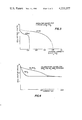
- FIG. 3 shows empirical discharge curves for Li/PC 1 M LiClO 4 /TiS 2 .
- FIG. 4 shows empirical polarization curves for MoS 2 and Na y MoS 2 cathodes.
- the battery discharge current (which determines the rate of arrival of cations at the cathode surface) is higher than the rate at which cations can diffuse to the cathode interior, then full intercalation of the cathode will not occur. Rather, the surface of the cathode will become saturated with cations whereupon the battery voltage will drop to zero, corresponding to a fully discharged condition. Such premature saturation of the cathode surface corresponds to a capacity which is smaller than the maximum possible capacity, since cations are only deposited at sites in the surface region of the cathode.
- FIG. 1 shows a plot of theoretical battery capacity vs. discharge rate, based on equations (2a) and (2b).
- FIGS. 2a and 2b The theoretical dependence of F on available capacity, Q, and discharge current, I (as determined by equations (2a) and (2b)) is shown in FIGS. 2a and 2b.
- Presently available experimental intercalation batteries have Figures of Merit, F M , in the range 200-2000 (watt-hrs./kg) 2 sec -1 . Although these cells have high capacity, their discharge current is relatively low.
- Figure of Merit of conventional lead-acid batteries is about 400 (watt-hrs./kg) 2 sec -1 . Although such batteries have relatively low capacity, they are capable of very high discharge current.
- the present invention is concerned with a battery in which the characteristics of intercalation batteries are improved by reducing the effective cathode time constant, t. Very large improvements in cell capacity and discharge current result, particularly in cases where the time constant characterizing the cathode is long, e.g. MoS 2 cathodes made of naturally occurring molybdenite.
- t is proportional to the square of the average cathode grain radius L, and inversely proportional to the cation diffusion coefficient, D, as recited in equation 1; t may be reduced by decreasing the grain size or by increasing the diffusion coefficient. Grain size may be reduced, e.g. by grinding, but it is not practical to reduce the average grain size much below 1 micron (10 -4 cm). Further reduction of t implies increasing the diffusion coefficient D. It is well known that this may be achieved by increasing the temperature. However, this approach is often undesirable in battery applications, since it implies that some means of heating must be provided.
- discharge current is affected by cation diffusion.
- the inventors believe that in some cases, e.g. where there is very small cathode material grain size, discharge current may be affected predominantly by other physical mechanisms, in which cases intercalation of a dopant may not significantly improve discharge current, except possibly at low temperatures where cation diffusion proceeds at a slower rate.
- D diffusion coefficient
- the van der Waals gap may be widened by intercalating small amounts of ions of larger ionic radius than the cations which are to be diffused into the cathode during battery discharge. Widening of the van der Waals gap in this manner facilitates subsequent cation diffusion.
- the cathode may be pre-treated with large ions by intercalating them into the cathode in any manner known to the art.
- van der Waals gap is so narrow that cations cannot readily enter the lattice structure, they tend to clog the surface of the structure. If the van der Waals gap is widened, cations will be more readily diffused into the lattice structure.
- the additive material used to spread adjacent molecular layers apart has been termed herein a "dopant.”
- the lattice structure is first treated with a dopant having a larger ionic radius than lithium ions to ease their subsequent intercalation between the molecular layers of the lattice structure.
- a dopant having a larger ionic radius than lithium ions to ease their subsequent intercalation between the molecular layers of the lattice structure.
- the sodium ion which has an ionic radius of 0.98 angstroms is a suitable dopant for the intercalation of the lithium ion which has an ionic radius of 0.68 angstroms.
- any atomic or ionic material having a larger ionic radius than the cations to be intercalated into the cathode may be used as a dopant, provided the dopant does not react chemically with either the cathode or with the cations or otherwise interfere with the operation of the battery.
- the ionic diameter of the dopant should exceed the cation diameter by at least 0.1 angstroms.
- the capacity of a given battery is proportional to the number of sites available in the cathode lattice structure for deposit of cations.
- sites occur in the van der Waals gap at symmetrically recurring intervals defined by the relative spacing or positioning of adjacent molecular layers.
- the amount of dopant present should spread adjacent molecular layers sufficiently far apart to facilitate the entry of cations. In some cases, deposit of dopant ions at as few as 5% of the sites where cations may rest will serve to spread the molecular layers sufficiently to facilitate entry of cations. In other cases, deposit of dopant at up to 40% of the potential sites for cations may be required. Deposit of dopant ions at more than 40% of the potential sites will not increase the distance between adjacent molecular layers so further doping appears unnecessary. Stated another way, x in A x MoS 2 ranges between 0.05 and 0.4 where A is the cathode dopant material.
- the cathode materials where TiS 2 or MoS 2 were Li + or Mg ++ and the cathode dopants were Na or K.
- electrolytes were used including LiClO 4 in propylene carbonate (PC) or Tetrahydrofuran-Dimethoxyethane (THF:DMOE 7:3), LiBr in propylene carbonate and MgCl 2 in H 2 O.
- PC propylene carbonate
- THF:DMOE 7:3 Tetrahydrofuran-Dimethoxyethane
- MgCl 2 in H 2 O.
- the intercalation of hydrated Mg is followed by in situ conversion to Mg(OH) 2 accompanied by H 2 evolution.
- a battery was constructed using lithium as the anode and a single flake of molybdenum disulfide as the cathode with acetonitrile containing 1 M LiClO 4 as the electrolyte.
- the cathode was not treated with dopant in this example.
- the open circuit voltage of the battery was found to be 2.86 volts and the initial short circuit current was found to be 0.8 milliamps.
- a battery was constructed with the identical materials as in Example 1, except that between 10% and 50% of the sites where the Li + cations would rest were previously doped with potassium ions. Doping was accomplished by dissolving potassium in liquid ammonia and inserting the molybdenum disulphide crystal in the resulting solution. The potassium ions spontaneously soak into the MoS 2 lattice structure. This battery was tested and found to have an open circuit voltage of 2.5 volts, slightly less than the open circuit voltage of the nondoped battery of Example 1. The short circuit current was found to be 17 milliamps, as compared to the 0.8 milliamps of the non-doped battery in Example 1.
- FIG. 4 shows polarization curves for two cells, namely Li/THF:DMOE (7:3)LiClO 4 /MoS 2 and Li/THF:DMOE (7:3) LiClO 4 /Na y MoS 2 .
- the two cells were identical in every respect (cathode weight 13 mg) except that the cathode of the Na y MoS 2 cell had been pretreated with a Na dopant using the ammonia process.
- the amount of Na dopant added was small, corresponding to y ⁇ 0.2 in Na y MoS 2 .
- the two cells show a high voltage (V>1.6 volts) intercalation regime and a low voltage regime (V ⁇ 1.6 volts) corresponding to electrolyte decomposition.
- the transition to this second regime occurs at very small current levels (I ⁇ 20 ⁇ a) with the pure MoS 2 cathode whereas it is delayed to a current of about 120 ⁇ a with the Na y MoS 2 cathode.
- I ⁇ 20 ⁇ a very small current levels
- doping the cathode of a layered transition metal dichalcogenide battery increases the storage density substantially, especially at large discharge current densities, by facilitating diffusion of cations into the lattice structure.
Abstract
Description
A.sub.x Z,
t=L.sup.2 /D (1)
It/Q.sub.M =y tanh y (2a)
Q/Q.sub.M =1/y tanh y (2b)
F=QI≅Q.sub.M.sup.2 /t ≡F.sub.M (3)
Claims (17)
Applications Claiming Priority (2)
| Application Number | Priority Date | Filing Date | Title |
|---|---|---|---|
| CA282,696A CA1081320A (en) | 1977-07-14 | 1977-07-14 | Battery with improved dichalcogenide cathode |
| CA282696 | 1977-07-14 |
Publications (1)
| Publication Number | Publication Date |
|---|---|
| US4233377A true US4233377A (en) | 1980-11-11 |
Family
ID=4109130
Family Applications (1)
| Application Number | Title | Priority Date | Filing Date |
|---|---|---|---|
| US05/922,199 Expired - Lifetime US4233377A (en) | 1977-07-14 | 1978-07-06 | Electrical storage device |
Country Status (2)
| Country | Link |
|---|---|
| US (1) | US4233377A (en) |
| CA (1) | CA1081320A (en) |
Cited By (16)
| Publication number | Priority date | Publication date | Assignee | Title |
|---|---|---|---|---|
| US4301221A (en) * | 1978-09-18 | 1981-11-17 | University Patents, Inc. | Chalcogenide electrochemical cell |
| EP0070107A1 (en) * | 1981-07-15 | 1983-01-19 | Rohm And Haas Company | Anhydrous cells |
| US4431718A (en) * | 1980-12-05 | 1984-02-14 | Societe Anonyme Dite: Compagnie Generale D'electricite | Electrochemical cell with a liquid negative electrode |
| US4687598A (en) * | 1983-11-07 | 1987-08-18 | The United States Of America As Represented By The United States Department Of Energy | Electrode-active material for electrochemical batteries and method of preparation |
| US4722877A (en) * | 1986-09-15 | 1988-02-02 | Eltron Research, Inc. | Long cycle life solid-state solid polymer electrolyte cells |
| US4822590A (en) * | 1986-04-23 | 1989-04-18 | Simon Fraser University | Forms of transition metal dichalcogenides |
| US5351164A (en) * | 1991-10-29 | 1994-09-27 | T.N. Frantsevich Institute For Problems In Materials Science | Electrolytic double layer capacitor |
| WO2003015196A2 (en) * | 2001-08-07 | 2003-02-20 | 3M Innovative Properties Company | Improved lithium-ion batteries |
| US20080014504A1 (en) * | 2006-07-14 | 2008-01-17 | Adrian Schneuwly | Method of making and article of manufacture for an energy storage electrode apparatus |
| US20080013255A1 (en) * | 2006-07-14 | 2008-01-17 | Adrian Schneuwly | Method of making and article of manufacture for an ultracapacitor electrode apparatus |
| US20080089006A1 (en) * | 2006-10-17 | 2008-04-17 | Maxwell Technologies, Inc. | Electrode for energy storage device |
| US20100008020A1 (en) * | 2008-07-09 | 2010-01-14 | Adrian Schneuwly | Electrode device |
| US20100075837A1 (en) * | 2008-09-25 | 2010-03-25 | Range Fuels, Inc. | Methods for promoting syngas-to-alcohol catalysts |
| JP2013237628A (en) * | 2012-05-14 | 2013-11-28 | Hiroshima Univ | Solid electrolyte and method of producing the same |
| US10734649B2 (en) * | 2015-11-24 | 2020-08-04 | The Regents Of The University Of California | Metal chalcogenides for pseudocapacitive applications |
| US11417884B2 (en) | 2017-12-20 | 2022-08-16 | Cornell University | Titanium disulfide-sulfur composites |
Citations (5)
| Publication number | Priority date | Publication date | Assignee | Title |
|---|---|---|---|---|
| US4009052A (en) * | 1975-02-24 | 1977-02-22 | Exxon Research And Engineering Company | Chalcogenide battery |
| US4049887A (en) * | 1976-07-20 | 1977-09-20 | Exxon Research & Engineering Co. | Electrochemical cells with cathode-active materials of layered compounds |
| US4049879A (en) * | 1976-04-19 | 1977-09-20 | Exxon Research & Engineering Co. | Intercalated transition metal phosphorus trisulfides |
| US4084046A (en) * | 1975-05-09 | 1978-04-11 | Exxon Research & Engineering Co. | Rechargeable electrochemical cell with cathode of stoichiometric titanium disulfide |
| US4091191A (en) * | 1976-12-17 | 1978-05-23 | Exxon Research & Engineering Co. | Battery having an electrode comprising mixtures of Al and TiS2 |
-
1977
- 1977-07-14 CA CA282,696A patent/CA1081320A/en not_active Expired
-
1978
- 1978-07-06 US US05/922,199 patent/US4233377A/en not_active Expired - Lifetime
Patent Citations (5)
| Publication number | Priority date | Publication date | Assignee | Title |
|---|---|---|---|---|
| US4009052A (en) * | 1975-02-24 | 1977-02-22 | Exxon Research And Engineering Company | Chalcogenide battery |
| US4084046A (en) * | 1975-05-09 | 1978-04-11 | Exxon Research & Engineering Co. | Rechargeable electrochemical cell with cathode of stoichiometric titanium disulfide |
| US4049879A (en) * | 1976-04-19 | 1977-09-20 | Exxon Research & Engineering Co. | Intercalated transition metal phosphorus trisulfides |
| US4049887A (en) * | 1976-07-20 | 1977-09-20 | Exxon Research & Engineering Co. | Electrochemical cells with cathode-active materials of layered compounds |
| US4091191A (en) * | 1976-12-17 | 1978-05-23 | Exxon Research & Engineering Co. | Battery having an electrode comprising mixtures of Al and TiS2 |
Cited By (22)
| Publication number | Priority date | Publication date | Assignee | Title |
|---|---|---|---|---|
| US4301221A (en) * | 1978-09-18 | 1981-11-17 | University Patents, Inc. | Chalcogenide electrochemical cell |
| US4431718A (en) * | 1980-12-05 | 1984-02-14 | Societe Anonyme Dite: Compagnie Generale D'electricite | Electrochemical cell with a liquid negative electrode |
| EP0070107A1 (en) * | 1981-07-15 | 1983-01-19 | Rohm And Haas Company | Anhydrous cells |
| US4687598A (en) * | 1983-11-07 | 1987-08-18 | The United States Of America As Represented By The United States Department Of Energy | Electrode-active material for electrochemical batteries and method of preparation |
| US4822590A (en) * | 1986-04-23 | 1989-04-18 | Simon Fraser University | Forms of transition metal dichalcogenides |
| US4722877A (en) * | 1986-09-15 | 1988-02-02 | Eltron Research, Inc. | Long cycle life solid-state solid polymer electrolyte cells |
| US5351164A (en) * | 1991-10-29 | 1994-09-27 | T.N. Frantsevich Institute For Problems In Materials Science | Electrolytic double layer capacitor |
| KR100920964B1 (en) | 2001-08-07 | 2009-10-09 | 쓰리엠 이노베이티브 프로퍼티즈 캄파니 | Improved lithium-ion batteries |
| WO2003015196A2 (en) * | 2001-08-07 | 2003-02-20 | 3M Innovative Properties Company | Improved lithium-ion batteries |
| WO2003015196A3 (en) * | 2001-08-07 | 2003-11-13 | 3M Innovative Properties Co | Improved lithium-ion batteries |
| US6680145B2 (en) | 2001-08-07 | 2004-01-20 | 3M Innovative Properties Company | Lithium-ion batteries |
| US20080014504A1 (en) * | 2006-07-14 | 2008-01-17 | Adrian Schneuwly | Method of making and article of manufacture for an energy storage electrode apparatus |
| US7580243B2 (en) | 2006-07-14 | 2009-08-25 | Maxwell Technologies, Inc. | Method of making and article of manufacture for an ultracapacitor electrode apparatus |
| US20080013255A1 (en) * | 2006-07-14 | 2008-01-17 | Adrian Schneuwly | Method of making and article of manufacture for an ultracapacitor electrode apparatus |
| US20080089006A1 (en) * | 2006-10-17 | 2008-04-17 | Maxwell Technologies, Inc. | Electrode for energy storage device |
| US20100110612A1 (en) * | 2006-10-17 | 2010-05-06 | Maxwell Technologies, Inc. | Electrode for energy storage device |
| US20100008020A1 (en) * | 2008-07-09 | 2010-01-14 | Adrian Schneuwly | Electrode device |
| US20100075837A1 (en) * | 2008-09-25 | 2010-03-25 | Range Fuels, Inc. | Methods for promoting syngas-to-alcohol catalysts |
| US8110522B2 (en) * | 2008-09-25 | 2012-02-07 | Range Fuels, Inc. | Methods for promoting syngas-to-alcohol catalysts |
| JP2013237628A (en) * | 2012-05-14 | 2013-11-28 | Hiroshima Univ | Solid electrolyte and method of producing the same |
| US10734649B2 (en) * | 2015-11-24 | 2020-08-04 | The Regents Of The University Of California | Metal chalcogenides for pseudocapacitive applications |
| US11417884B2 (en) | 2017-12-20 | 2022-08-16 | Cornell University | Titanium disulfide-sulfur composites |
Also Published As
| Publication number | Publication date |
|---|---|
| CA1081320A (en) | 1980-07-08 |
Similar Documents
| Publication | Publication Date | Title |
|---|---|---|
| US4233377A (en) | Electrical storage device | |
| US4228226A (en) | Nonaqueous secondary cell using vanadium oxide positive electrode | |
| CA1043867A (en) | Cathode comprising a transition metal chalcogenide in a carbon matrix | |
| Williams et al. | A high energy density lithium/dichloroisocyanuric acid battery system | |
| Miki et al. | Amorphous MoS2 as the cathode of lithium secondary batteries | |
| US4450214A (en) | Lithium halide additives for nonaqueous cell systems | |
| DE3136820C2 (en) | ||
| DE2928863C2 (en) | Electrochemical cell | |
| EP0974169B1 (en) | An iron-based storage battery | |
| US4125687A (en) | Rechargeable nonaqueous cell with chalcogenide electrode | |
| DE2817708C2 (en) | Galvanic element with solid electrolyte | |
| CH495061A (en) | Rechargeable, electrochemical cell | |
| DD159387A5 (en) | SECONDARY ELEMENTS BASED ON ELECTROCHEMICALLY DOTABLE CONJUGATED POLYMERS | |
| EP1201004A1 (en) | Rechargeable electrochemical cell | |
| GB2164786A (en) | Sodium aluminium halide cell | |
| DE2628752A1 (en) | ELECTROCHEMICAL ELEMENT | |
| DE2810795A1 (en) | ELECTRODE FOR ELECTRICAL STORAGE DEVICES | |
| CA1161495A (en) | Rechargeable nonaqueous silver alloy anode cell | |
| US5298349A (en) | Method of pretreating a cathode for attaining a stable voltage upon cell assembly | |
| US4624902A (en) | Coatings for electrochemical electrodes and methods of making the same | |
| DE2701708A1 (en) | ELECTRODE FOR A DEVICE FOR STORING ELECTRICAL ENERGY | |
| Takeda et al. | Lithium organic electrolyte cells using the copper chevrel phase as cathode | |
| DE2356914A1 (en) | SECONDARY BATTERY | |
| DE2544882A1 (en) | LITHIUM ELECTRODE | |
| US4224390A (en) | Lithium molybdenum disulphide battery cathode |
Legal Events
| Date | Code | Title | Description |
|---|---|---|---|
| AS | Assignment |
Owner name: MOLI ENERGY LTD., 1199 WEST HASTINGS ST., VANCOUVE Free format text: ASSIGNMENT OF ASSIGNORS INTEREST.;ASSIGNOR:UNIVERSITY OF BRITISH COLUMBIA THE;REEL/FRAME:003962/0715 Effective date: 19811009 Owner name: UNIVERSITY OF BRITISH COLUMBIA, THE, BRITISH COLUM Free format text: ASSIGNMENT OF ASSIGNORS INTEREST;ASSIGNORS:HAERING, RUDOLPH R.;STILES, JAMES A.R.;SIGNING DATES FROM 19810914 TO 19810915;REEL/FRAME:003962/0713 Owner name: UNIVERSITY OF BRITISH COLUMBIA THE, A CORP. OF BRI Free format text: ASSIGNMENT OF ASSIGNORS INTEREST.;ASSIGNORS:HAERING, RUDOLPH R.;STILES, JAMES A.R.;REEL/FRAME:003962/0713;SIGNING DATES FROM 19810914 TO 19810915 |
|
| AS | Assignment |
Owner name: BRITISH COLUMBIA DEVELOPMENT CORPORATION 272 - 200 Free format text: ASSIGNMENT OF ASSIGNORS INTEREST.;ASSIGNOR:MOLI ENERGY LIMITED;REEL/FRAME:004346/0692 |
|
| AS | Assignment |
Owner name: MOLI ENERGY (1990) LIMITED, A CORP. OF BRITISH C Free format text: LICENSE;ASSIGNOR:HER MAJESTY THE QUEEN IN RIGHT OF THE PROVINCE OF BRITISH COLUMBIA, CANADA;REEL/FRAME:005518/0010 Effective date: 19900430 Owner name: HER MAJESTY THE QUEEN IN RIGHT OF THE PROVINCE OF Free format text: SECURITY INTEREST;ASSIGNOR:MOLI ENERGY LIMITED;REEL/FRAME:005614/0688 Effective date: 19901114 |