US4259389A - High pressure-low porosity wet seal - Google Patents
High pressure-low porosity wet seal Download PDFInfo
- Publication number
- US4259389A US4259389A US05/972,600 US97260078A US4259389A US 4259389 A US4259389 A US 4259389A US 97260078 A US97260078 A US 97260078A US 4259389 A US4259389 A US 4259389A
- Authority
- US
- United States
- Prior art keywords
- seal
- substrate
- cell
- microns
- clamped
- Prior art date
- Legal status (The legal status is an assumption and is not a legal conclusion. Google has not performed a legal analysis and makes no representation as to the accuracy of the status listed.)
- Expired - Lifetime
Links
Images
Classifications
-
- H—ELECTRICITY
- H01—ELECTRIC ELEMENTS
- H01M—PROCESSES OR MEANS, e.g. BATTERIES, FOR THE DIRECT CONVERSION OF CHEMICAL ENERGY INTO ELECTRICAL ENERGY
- H01M8/00—Fuel cells; Manufacture thereof
- H01M8/02—Details
- H01M8/0271—Sealing or supporting means around electrodes, matrices or membranes
-
- Y—GENERAL TAGGING OF NEW TECHNOLOGICAL DEVELOPMENTS; GENERAL TAGGING OF CROSS-SECTIONAL TECHNOLOGIES SPANNING OVER SEVERAL SECTIONS OF THE IPC; TECHNICAL SUBJECTS COVERED BY FORMER USPC CROSS-REFERENCE ART COLLECTIONS [XRACs] AND DIGESTS
- Y02—TECHNOLOGIES OR APPLICATIONS FOR MITIGATION OR ADAPTATION AGAINST CLIMATE CHANGE
- Y02E—REDUCTION OF GREENHOUSE GAS [GHG] EMISSIONS, RELATED TO ENERGY GENERATION, TRANSMISSION OR DISTRIBUTION
- Y02E60/00—Enabling technologies; Technologies with a potential or indirect contribution to GHG emissions mitigation
- Y02E60/30—Hydrogen technology
- Y02E60/50—Fuel cells
-
- Y—GENERAL TAGGING OF NEW TECHNOLOGICAL DEVELOPMENTS; GENERAL TAGGING OF CROSS-SECTIONAL TECHNOLOGIES SPANNING OVER SEVERAL SECTIONS OF THE IPC; TECHNICAL SUBJECTS COVERED BY FORMER USPC CROSS-REFERENCE ART COLLECTIONS [XRACs] AND DIGESTS
- Y10—TECHNICAL SUBJECTS COVERED BY FORMER USPC
- Y10T—TECHNICAL SUBJECTS COVERED BY FORMER US CLASSIFICATION
- Y10T428/00—Stock material or miscellaneous articles
- Y10T428/24—Structurally defined web or sheet [e.g., overall dimension, etc.]
- Y10T428/24777—Edge feature
-
- Y—GENERAL TAGGING OF NEW TECHNOLOGICAL DEVELOPMENTS; GENERAL TAGGING OF CROSS-SECTIONAL TECHNOLOGIES SPANNING OVER SEVERAL SECTIONS OF THE IPC; TECHNICAL SUBJECTS COVERED BY FORMER USPC CROSS-REFERENCE ART COLLECTIONS [XRACs] AND DIGESTS
- Y10—TECHNICAL SUBJECTS COVERED BY FORMER USPC
- Y10T—TECHNICAL SUBJECTS COVERED BY FORMER US CLASSIFICATION
- Y10T428/00—Stock material or miscellaneous articles
- Y10T428/24—Structurally defined web or sheet [e.g., overall dimension, etc.]
- Y10T428/24802—Discontinuous or differential coating, impregnation or bond [e.g., artwork, printing, retouched photograph, etc.]
- Y10T428/24893—Discontinuous or differential coating, impregnation or bond [e.g., artwork, printing, retouched photograph, etc.] including particulate material
-
- Y—GENERAL TAGGING OF NEW TECHNOLOGICAL DEVELOPMENTS; GENERAL TAGGING OF CROSS-SECTIONAL TECHNOLOGIES SPANNING OVER SEVERAL SECTIONS OF THE IPC; TECHNICAL SUBJECTS COVERED BY FORMER USPC CROSS-REFERENCE ART COLLECTIONS [XRACs] AND DIGESTS
- Y10—TECHNICAL SUBJECTS COVERED BY FORMER USPC
- Y10T—TECHNICAL SUBJECTS COVERED BY FORMER US CLASSIFICATION
- Y10T428/00—Stock material or miscellaneous articles
- Y10T428/25—Web or sheet containing structurally defined element or component and including a second component containing structurally defined particles
- Y10T428/259—Silicic material
-
- Y—GENERAL TAGGING OF NEW TECHNOLOGICAL DEVELOPMENTS; GENERAL TAGGING OF CROSS-SECTIONAL TECHNOLOGIES SPANNING OVER SEVERAL SECTIONS OF THE IPC; TECHNICAL SUBJECTS COVERED BY FORMER USPC CROSS-REFERENCE ART COLLECTIONS [XRACs] AND DIGESTS
- Y10—TECHNICAL SUBJECTS COVERED BY FORMER USPC
- Y10T—TECHNICAL SUBJECTS COVERED BY FORMER US CLASSIFICATION
- Y10T428/00—Stock material or miscellaneous articles
- Y10T428/29—Coated or structually defined flake, particle, cell, strand, strand portion, rod, filament, macroscopic fiber or mass thereof
- Y10T428/2982—Particulate matter [e.g., sphere, flake, etc.]
- Y10T428/2991—Coated
- Y10T428/2993—Silicic or refractory material containing [e.g., tungsten oxide, glass, cement, etc.]
-
- Y—GENERAL TAGGING OF NEW TECHNOLOGICAL DEVELOPMENTS; GENERAL TAGGING OF CROSS-SECTIONAL TECHNOLOGIES SPANNING OVER SEVERAL SECTIONS OF THE IPC; TECHNICAL SUBJECTS COVERED BY FORMER USPC CROSS-REFERENCE ART COLLECTIONS [XRACs] AND DIGESTS
- Y10—TECHNICAL SUBJECTS COVERED BY FORMER USPC
- Y10T—TECHNICAL SUBJECTS COVERED BY FORMER US CLASSIFICATION
- Y10T428/00—Stock material or miscellaneous articles
- Y10T428/31504—Composite [nonstructural laminate]
- Y10T428/3154—Of fluorinated addition polymer from unsaturated monomers
- Y10T428/31544—Addition polymer is perhalogenated
Definitions
- the present invention has as one feature the use of a powder filler of varying particle size which minimizes porosity by ability to produce a denser packing.
- This denser packing reduces compressibility and assures a better seal.
- Another feature is the use of a Teflon® or the like binder for this powder filler which is inert to the acid of the cell and to the filler and will hold the particles securely in the compacted condition.
- the edge or edges of the substrate for the fuel cell are coated or impregnated with a seal material consisting of powdered silicon carbide, carbon or graphite or the like of varying particle size from, for example, 10 to 0.1 microns and bonded with Teflon or the like to provide a very dense, relatively incompressible wet seal to minimize gas leakage from the cell.
- a seal material consisting of powdered silicon carbide, carbon or graphite or the like of varying particle size from, for example, 10 to 0.1 microns and bonded with Teflon or the like to provide a very dense, relatively incompressible wet seal to minimize gas leakage from the cell.
- FIG. 1 is a sectional view through a part of a fuel cell utilizing the seal.
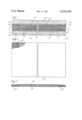
- FIG. 2 is a plan view of a substrate with the seal on opposite edges.
- FIG. 3 is a sectional view through the substrate of FIG. 2 on an exaggerated scale.
- the sectional view through a part of a fuel cell shows a gas distribution plate 2 having flat sealing surfaces 4 at opposite edges for a seal and having a plurality of parallel gas circulating grooves 6 between the surfaces 4.
- the opposite surface of the plate has sealing surfaces 8 at right angles to the surfaces 4 and gas circulating grooves 10 at right angles to the grooves 6.
- These grooves 10 and surfaces 8 form a part of the adjacent unitary cell in a stack of cells.
- Such a structure is well known.
- a substrate 12 which forms one of the electrodes of the cell and is a porous material for the passage of gas therethrough from the grooves 6.
- the surface of the substrate 12 opposite to the grooves will routinely have a catalyst coating 14 thereon.
- the substrate is porous and may be, for example, a random carbon fiber sheet. It will be understood that the thickness of certain elements is exaggerated in the drawing for the purpose of clarity.
- a layer of a matrix 16 that serves to electrically isolate the electrodes and to retain the electrolyte in the cell.
- This matrix may be of any of the well known materials used for this purpose. It is normally a porous material, generally less porous than the substrate and may be one or more layers. Both the substrate and the matrix are the same area and shape as the distribution plate so that the edges will be engaged and clamped between adjacent distribution plates at their sealing surfaces.
- the other substrate 18 of the unitary cell On the side of the matrix opposite to the substrate 12 is the other substrate 18 of the unitary cell. This will normally be the same material as the substrate 12 and will have a catalyst 20 thereon but on the side facing the matrix.
- One of these substrates is the fuel electrode and the other the oxidant electrode of the unitary cell.
- a distributor plate 22 similar to the plate 2 is placed on the substrate 18 as shown.
- a fuel cell assembly a stack of such cells is built up and the assembly is then clamped securely so that the opposite edges of the substrates and the matrix are clamped between adjacent distributor plates.
- the substrates have sealing areas 24 at opposite edges to cooperate with the sealing surfaces on the plates. These sealing areas are preferably made by coating or impregnating these areas of the substrate with a silicon carbide powder bonded together with about 2% of Teflon or Teflon-like polytetrafluoroethylene material to hold the powdered material in its compacted condition. Carbon or graphite may be used in conjunction with or instead of silicon carbide powder or other materials inert to the electrolyte used in the cell.
- the powdered material of the seal is made up of particles of varying size from 10 to 0.1 microns as this has been found to maximize the effectiveness of the seal.
- sealing areas at the edges of the substrate may be produced in any of several ways, for example, the particles of varying size, with the binder particles therewith are mixed in a suitable slurry into which the edges of the substrate may be dipped to the right depth (width of seal area on substrate) and then dried.
- An alternative procedure may be an application of the mixture of sealant powder and binder in a suitable vehicle such as water by the silk screen process. Other techniques will be apparent.
- the substrate is coated with or impregnated with the sealant material to produce such a thickness and width on the opposite edge areas of the substrate that when the cell elements are assembled and clamped in a unit, the sealant material will form an effective seal when wetted by the electrolyte and form such a dense seal barrier at the edges of the substrates as to prevent or minimize the escape of gas bubbles from the cell stack when the cell is put into operation by a supply of gaseous oxidant and fuel to opposite sides of the distributor plates.
Abstract
A high pressure, low porosity wet seal for a substrate in a fuel cell in which the seal is made up of a granular material having a particle size varying from 10 to 0.1 microns in size bonded together with polytetrafluoroethylene to prevent leakage of the gaseous fuel or oxidant from the cell.
Description
This is a continuation of application Ser. No. 859,884 filed on Dec. 12, 1977 now abandoned.
In preparing a wet seal to be applied to the edges of a substrate it has been routine to select a particular relatively large particle size for the powder filler used in the impregnation or coating that forms the seal. It has been found that this does not allow adequately dense packing to assure a relatively low porosity. Not only does leakage of the gaseous fuel or oxidant occur but the seal may be still somewhat compressible when the cell components are assembled and may not seal securely against the associated separator plate and associated elements.
Accordingly, the present invention has as one feature the use of a powder filler of varying particle size which minimizes porosity by ability to produce a denser packing. This denser packing reduces compressibility and assures a better seal. Another feature is the use of a Teflon® or the like binder for this powder filler which is inert to the acid of the cell and to the filler and will hold the particles securely in the compacted condition.
According to the invention, the edge or edges of the substrate for the fuel cell are coated or impregnated with a seal material consisting of powdered silicon carbide, carbon or graphite or the like of varying particle size from, for example, 10 to 0.1 microns and bonded with Teflon or the like to provide a very dense, relatively incompressible wet seal to minimize gas leakage from the cell.
The foregoing and other objects, features, and advantages of the present invention will become more apparent in the light of the following detailed description of preferred embodiments thereof as illustrated in the accompanying drawing.
FIG. 1 is a sectional view through a part of a fuel cell utilizing the seal.
FIG. 2 is a plan view of a substrate with the seal on opposite edges.
FIG. 3 is a sectional view through the substrate of FIG. 2 on an exaggerated scale.
Referring first to FIG. 1, the sectional view through a part of a fuel cell shows a gas distribution plate 2 having flat sealing surfaces 4 at opposite edges for a seal and having a plurality of parallel gas circulating grooves 6 between the surfaces 4. The opposite surface of the plate has sealing surfaces 8 at right angles to the surfaces 4 and gas circulating grooves 10 at right angles to the grooves 6. These grooves 10 and surfaces 8 form a part of the adjacent unitary cell in a stack of cells. Such a structure is well known.
Resting on the plate 2 is a substrate 12 which forms one of the electrodes of the cell and is a porous material for the passage of gas therethrough from the grooves 6. The surface of the substrate 12 opposite to the grooves will routinely have a catalyst coating 14 thereon. The substrate is porous and may be, for example, a random carbon fiber sheet. It will be understood that the thickness of certain elements is exaggerated in the drawing for the purpose of clarity.
Above the surface of the substrate and catalyst is a layer of a matrix 16 that serves to electrically isolate the electrodes and to retain the electrolyte in the cell. This matrix may be of any of the well known materials used for this purpose. It is normally a porous material, generally less porous than the substrate and may be one or more layers. Both the substrate and the matrix are the same area and shape as the distribution plate so that the edges will be engaged and clamped between adjacent distribution plates at their sealing surfaces.
On the side of the matrix opposite to the substrate 12 is the other substrate 18 of the unitary cell. This will normally be the same material as the substrate 12 and will have a catalyst 20 thereon but on the side facing the matrix. One of these substrates is the fuel electrode and the other the oxidant electrode of the unitary cell.
A distributor plate 22 similar to the plate 2 is placed on the substrate 18 as shown. In a fuel cell assembly a stack of such cells is built up and the assembly is then clamped securely so that the opposite edges of the substrates and the matrix are clamped between adjacent distributor plates.
To prevent leakage of gas from within the cell the substrates have sealing areas 24 at opposite edges to cooperate with the sealing surfaces on the plates. These sealing areas are preferably made by coating or impregnating these areas of the substrate with a silicon carbide powder bonded together with about 2% of Teflon or Teflon-like polytetrafluoroethylene material to hold the powdered material in its compacted condition. Carbon or graphite may be used in conjunction with or instead of silicon carbide powder or other materials inert to the electrolyte used in the cell. The powdered material of the seal is made up of particles of varying size from 10 to 0.1 microns as this has been found to maximize the effectiveness of the seal. Although this variation in size is desirable, for convenience it has been found that a narrower range of sizes from 10 to 1 microns or a narrower range from 5 to 1 microns with the maximum size 5 microns are adequate in most instances. This variation in size will usually produce the necessary density and incompressibility when in use as to minimize the leakage from the cell.
These sealing areas at the edges of the substrate may be produced in any of several ways, for example, the particles of varying size, with the binder particles therewith are mixed in a suitable slurry into which the edges of the substrate may be dipped to the right depth (width of seal area on substrate) and then dried. An alternative procedure may be an application of the mixture of sealant powder and binder in a suitable vehicle such as water by the silk screen process. Other techniques will be apparent. In either event, the substrate is coated with or impregnated with the sealant material to produce such a thickness and width on the opposite edge areas of the substrate that when the cell elements are assembled and clamped in a unit, the sealant material will form an effective seal when wetted by the electrolyte and form such a dense seal barrier at the edges of the substrates as to prevent or minimize the escape of gas bubbles from the cell stack when the cell is put into operation by a supply of gaseous oxidant and fuel to opposite sides of the distributor plates.
Although the invention has been shown and described with respect to a preferred embodiment thereof, it should be understood by those skilled in the art that other various changes and omissions in the form and detail thereof may be made therein without departing from the spirit and the scope of the invention.
Claims (4)
1. A porous electrode substrate for a fuel cell having a seal portion along at least one edge thereof where the substrate is clamped by the sealing surfaces of the distributor plates of the cell, the seal being in a band along the edge of the electrode to prevent leakage of gas from the cell, the band being substantially the width of the sealing surfaces of the plates and in a position to be clamped thereby, the seal consisting of an inert powder selected from the group consisting of silicon carbide, carbon or graphite, this powder having a variable particle size from 10 to 0.1 microns and being mixed with about 2% of polytetrafluoroethylene as a binder, this sealing material being in a band on the substrate of such thickness and width as to be clamped by the distributor plates and prevent gas leakage past said seal during fuel cell operation.
2. A porous electrode substrate as in claim 1 in which the maximum particle size for the seal material is about 5 microns.
3. A porous electrode substrate as in claim 1 in which the size range for the seal particles is from 5 to 1 microns.
4. A porous electrode substrate as in claim 1 in which the inert powder is silicon carbide.
Priority Applications (1)
| Application Number | Priority Date | Filing Date | Title |
|---|---|---|---|
| US05/972,600 US4259389A (en) | 1977-12-12 | 1978-12-22 | High pressure-low porosity wet seal |
Applications Claiming Priority (2)
| Application Number | Priority Date | Filing Date | Title |
|---|---|---|---|
| US85988477A | 1977-12-12 | 1977-12-12 | |
| US05/972,600 US4259389A (en) | 1977-12-12 | 1978-12-22 | High pressure-low porosity wet seal |
Related Parent Applications (1)
| Application Number | Title | Priority Date | Filing Date |
|---|---|---|---|
| US85988477A Continuation | 1977-12-12 | 1977-12-12 |
Publications (1)
| Publication Number | Publication Date |
|---|---|
| US4259389A true US4259389A (en) | 1981-03-31 |
Family
ID=27127549
Family Applications (1)
| Application Number | Title | Priority Date | Filing Date |
|---|---|---|---|
| US05/972,600 Expired - Lifetime US4259389A (en) | 1977-12-12 | 1978-12-22 | High pressure-low porosity wet seal |
Country Status (1)
| Country | Link |
|---|---|
| US (1) | US4259389A (en) |
Cited By (31)
| Publication number | Priority date | Publication date | Assignee | Title |
|---|---|---|---|---|
| DE3216824A1 (en) * | 1981-05-14 | 1982-12-16 | United Technologies Corp., 06101 Hartford, Conn. | AT HIGH TEMPERATURE AND PRESSURE, CHEMICAL-RESISTANT SEALING MATERIAL |
| JPS58135577A (en) * | 1982-02-08 | 1983-08-12 | Hitachi Ltd | Fuel cell |
| US4450212A (en) * | 1982-09-30 | 1984-05-22 | Engelhard Corporation | Edge seal for a porous gas distribution plate of a fuel cell |
| EP0110517A1 (en) * | 1982-09-30 | 1984-06-13 | Engelhard Corporation | Integral gas seal for a fuel cell gas distribution plate and process for forming seal |
| EP0123960A1 (en) * | 1983-04-06 | 1984-11-07 | Energy Research Corporation | Fuel cell assembly with silicon carbide shims and method of making such shims |
| EP0125595A1 (en) * | 1983-05-09 | 1984-11-21 | Kabushiki Kaisha Toshiba | Porous gas diffusion electrode and method of producing the same |
| US4652502A (en) * | 1985-12-30 | 1987-03-24 | International Fuel Cells, Inc. | Porous plate for an electrochemical cell and method for making the porous plate |
| US4670300A (en) * | 1985-07-03 | 1987-06-02 | International Fuel Cells Corporation | Carbon-graphite component for an electrochemical cell and method for making the component |
| US4728533A (en) * | 1982-09-30 | 1988-03-01 | Engelhard Corporation | Process for forming integral edge seals in porous gas distribution plates utilizing a vibratory means |
| US4738872A (en) * | 1985-07-02 | 1988-04-19 | International Fuel Cells | Carbon-graphite component for an electrochemical cell and method for making the component |
| US4756981A (en) * | 1986-12-29 | 1988-07-12 | International Fuel Cells | Seal structure for an electrochemical cell |
| US4786568A (en) * | 1988-03-01 | 1988-11-22 | International Fuel Cells Corporation | Electrode substrate with integral edge seal and method of forming the same |
| US4938942A (en) * | 1985-07-17 | 1990-07-03 | International Fuel Cells | Carbon graphite component for an electrochemical cell and method for making the component |
| US4963442A (en) * | 1989-05-03 | 1990-10-16 | Institute Of Gas Technology | Internal manifolded molten carbonate fuel cell stack |
| US5077148A (en) * | 1989-05-03 | 1991-12-31 | Institute Of Gas Technology | Fully internal manifolded and internal reformed fuel cell stack |
| US5093403A (en) * | 1986-07-01 | 1992-03-03 | Edlon Products, Inc. | Polymer-metal bonded composite and method of producing same |
| US5096786A (en) * | 1989-09-11 | 1992-03-17 | Westinghouse Electric Corp. | Integral edge seals for phosphoric acid fuel cells |
| US5141828A (en) * | 1990-05-14 | 1992-08-25 | Brigham Young University | Electrochemical system using bipolar electrode |
| US5227256A (en) * | 1989-05-03 | 1993-07-13 | Institute Of Gas Technology | Fully internal manifolded fuel cell stack |
| US5232792A (en) * | 1992-08-21 | 1993-08-03 | M-C Power Corporation | Cell separator plate used in fuel cell stacks |
| US5240786A (en) * | 1992-03-13 | 1993-08-31 | Institute Of Gas Technology | Laminated fuel cell components |
| US5298342A (en) * | 1992-10-20 | 1994-03-29 | M-C Power Corporation | Fuel cell crossover arrestor and pressure seal |
| US5342706A (en) * | 1989-05-03 | 1994-08-30 | Institute Of Gas Technology | Fully internal manifolded fuel cell stack |
| WO1995003638A1 (en) * | 1993-07-20 | 1995-02-02 | Bossel Ulf Dr | Process and device for reducing energy losses of electrochemical cells due to leakage currents |
| US5523175A (en) * | 1991-12-26 | 1996-06-04 | International Fuel Cells Corporation | Plate-shaped fuel cell component |
| US5536598A (en) * | 1994-10-12 | 1996-07-16 | Bipolar Technologies Corporation | Bipolar battery cells, batteries and methods |
| US5536583A (en) * | 1986-07-01 | 1996-07-16 | Edlon Products, Inc. | Polymer metal bonded composite and method of producing same |
| US5556627A (en) * | 1994-10-12 | 1996-09-17 | Bipolar Technologies, Inc. | Bipolar battery cells, batteries and methods |
| US5582937A (en) * | 1994-10-12 | 1996-12-10 | Bipolar Technologies, Inc. | Bipolar battery cells, batteries and methods |
| US5582622A (en) * | 1994-10-12 | 1996-12-10 | Bipolar Technologies, Inc. | Methods of making bipolar battery plates comprising carbon and a fluoroelastomer |
| DE102004048525A1 (en) * | 2004-10-06 | 2006-04-13 | Bayerische Motoren Werke Ag | Fuel cell stack manufacturing method, involves already adding stack during actual assembling under ambient temperature, and utilizing sealing medium with very small shrinkage and inserting before assembly of stack |
Citations (8)
| Publication number | Priority date | Publication date | Assignee | Title |
|---|---|---|---|---|
| US3282734A (en) * | 1961-09-26 | 1966-11-01 | Leesona Corp | Fuel cell with series of electrode sets |
| US3326722A (en) * | 1962-12-27 | 1967-06-20 | Leesona Corp | Fuel cell seal |
| US3702267A (en) * | 1970-06-15 | 1972-11-07 | Du Pont | Electrochemical cell containing a water-wettable polytetrafluoroethylene separator |
| US3713890A (en) * | 1970-01-28 | 1973-01-30 | Mc Donnell Douglas Corp | Flexible battery separator and method of production |
| US4048392A (en) * | 1976-12-13 | 1977-09-13 | Honeywell Inc. | Crimp seal using polyphenylene sulfide plastic with an aluminum terminal pan |
| US4052537A (en) * | 1976-10-01 | 1977-10-04 | P. R. Mallory & Co. Inc. | Electrical device |
| US4110518A (en) * | 1976-10-01 | 1978-08-29 | P.R. Mallory & Co. Inc. | Fluorocarbon seal |
| US4166157A (en) * | 1977-07-11 | 1979-08-28 | Exxon Research & Engineering Co. | Double sealable button cell with corrosion resistant can and method |
-
1978
- 1978-12-22 US US05/972,600 patent/US4259389A/en not_active Expired - Lifetime
Patent Citations (8)
| Publication number | Priority date | Publication date | Assignee | Title |
|---|---|---|---|---|
| US3282734A (en) * | 1961-09-26 | 1966-11-01 | Leesona Corp | Fuel cell with series of electrode sets |
| US3326722A (en) * | 1962-12-27 | 1967-06-20 | Leesona Corp | Fuel cell seal |
| US3713890A (en) * | 1970-01-28 | 1973-01-30 | Mc Donnell Douglas Corp | Flexible battery separator and method of production |
| US3702267A (en) * | 1970-06-15 | 1972-11-07 | Du Pont | Electrochemical cell containing a water-wettable polytetrafluoroethylene separator |
| US4052537A (en) * | 1976-10-01 | 1977-10-04 | P. R. Mallory & Co. Inc. | Electrical device |
| US4110518A (en) * | 1976-10-01 | 1978-08-29 | P.R. Mallory & Co. Inc. | Fluorocarbon seal |
| US4048392A (en) * | 1976-12-13 | 1977-09-13 | Honeywell Inc. | Crimp seal using polyphenylene sulfide plastic with an aluminum terminal pan |
| US4166157A (en) * | 1977-07-11 | 1979-08-28 | Exxon Research & Engineering Co. | Double sealable button cell with corrosion resistant can and method |
Cited By (39)
| Publication number | Priority date | Publication date | Assignee | Title |
|---|---|---|---|---|
| US4374185A (en) * | 1981-05-14 | 1983-02-15 | United Technologies Corporation | High temperature, high pressure chemical resistant seal material |
| DE3216824A1 (en) * | 1981-05-14 | 1982-12-16 | United Technologies Corp., 06101 Hartford, Conn. | AT HIGH TEMPERATURE AND PRESSURE, CHEMICAL-RESISTANT SEALING MATERIAL |
| JPS6240825B2 (en) * | 1982-02-08 | 1987-08-31 | Hitachi Ltd | |
| JPS58135577A (en) * | 1982-02-08 | 1983-08-12 | Hitachi Ltd | Fuel cell |
| US4450212A (en) * | 1982-09-30 | 1984-05-22 | Engelhard Corporation | Edge seal for a porous gas distribution plate of a fuel cell |
| EP0110517A1 (en) * | 1982-09-30 | 1984-06-13 | Engelhard Corporation | Integral gas seal for a fuel cell gas distribution plate and process for forming seal |
| US4728533A (en) * | 1982-09-30 | 1988-03-01 | Engelhard Corporation | Process for forming integral edge seals in porous gas distribution plates utilizing a vibratory means |
| EP0123960A1 (en) * | 1983-04-06 | 1984-11-07 | Energy Research Corporation | Fuel cell assembly with silicon carbide shims and method of making such shims |
| EP0125595A1 (en) * | 1983-05-09 | 1984-11-21 | Kabushiki Kaisha Toshiba | Porous gas diffusion electrode and method of producing the same |
| US4738872A (en) * | 1985-07-02 | 1988-04-19 | International Fuel Cells | Carbon-graphite component for an electrochemical cell and method for making the component |
| US4670300A (en) * | 1985-07-03 | 1987-06-02 | International Fuel Cells Corporation | Carbon-graphite component for an electrochemical cell and method for making the component |
| US4938942A (en) * | 1985-07-17 | 1990-07-03 | International Fuel Cells | Carbon graphite component for an electrochemical cell and method for making the component |
| GB2184883B (en) * | 1985-12-30 | 1989-10-18 | Int Fuel Cells Corp | Porous plate for an electrochemical cell and method for making the porous plate |
| DE3638856A1 (en) * | 1985-12-30 | 1987-07-02 | Int Fuel Cells Corp | POROESE PLATE FOR AN ELECTROCHEMICAL CELL AND METHOD FOR THE PRODUCTION THEREOF |
| FR2592528A1 (en) * | 1985-12-30 | 1987-07-03 | Int Fuel Cells Corp | POROUS PLATE FOR AN ELECTROCHEMICAL CELL AND MANUFACTURING METHOD THEREOF |
| GB2184883A (en) * | 1985-12-30 | 1987-07-01 | Int Fuel Cells Corp | Porous plate for an electrochemical cell and method for making the porous plate |
| US4652502A (en) * | 1985-12-30 | 1987-03-24 | International Fuel Cells, Inc. | Porous plate for an electrochemical cell and method for making the porous plate |
| US5093403A (en) * | 1986-07-01 | 1992-03-03 | Edlon Products, Inc. | Polymer-metal bonded composite and method of producing same |
| US5536583A (en) * | 1986-07-01 | 1996-07-16 | Edlon Products, Inc. | Polymer metal bonded composite and method of producing same |
| US4756981A (en) * | 1986-12-29 | 1988-07-12 | International Fuel Cells | Seal structure for an electrochemical cell |
| US4786568A (en) * | 1988-03-01 | 1988-11-22 | International Fuel Cells Corporation | Electrode substrate with integral edge seal and method of forming the same |
| EP0331128A3 (en) * | 1988-03-01 | 1990-10-17 | International Fuel Cells Corporation | Electrode substrate with integral edge seal and method of forming the same |
| EP0331128A2 (en) * | 1988-03-01 | 1989-09-06 | International Fuel Cells Corporation | Electrode substrate with integral edge seal and method of forming the same |
| US5077148A (en) * | 1989-05-03 | 1991-12-31 | Institute Of Gas Technology | Fully internal manifolded and internal reformed fuel cell stack |
| US4963442A (en) * | 1989-05-03 | 1990-10-16 | Institute Of Gas Technology | Internal manifolded molten carbonate fuel cell stack |
| US5227256A (en) * | 1989-05-03 | 1993-07-13 | Institute Of Gas Technology | Fully internal manifolded fuel cell stack |
| US5342706A (en) * | 1989-05-03 | 1994-08-30 | Institute Of Gas Technology | Fully internal manifolded fuel cell stack |
| US5096786A (en) * | 1989-09-11 | 1992-03-17 | Westinghouse Electric Corp. | Integral edge seals for phosphoric acid fuel cells |
| US5141828A (en) * | 1990-05-14 | 1992-08-25 | Brigham Young University | Electrochemical system using bipolar electrode |
| US5523175A (en) * | 1991-12-26 | 1996-06-04 | International Fuel Cells Corporation | Plate-shaped fuel cell component |
| US5240786A (en) * | 1992-03-13 | 1993-08-31 | Institute Of Gas Technology | Laminated fuel cell components |
| US5232792A (en) * | 1992-08-21 | 1993-08-03 | M-C Power Corporation | Cell separator plate used in fuel cell stacks |
| US5298342A (en) * | 1992-10-20 | 1994-03-29 | M-C Power Corporation | Fuel cell crossover arrestor and pressure seal |
| WO1995003638A1 (en) * | 1993-07-20 | 1995-02-02 | Bossel Ulf Dr | Process and device for reducing energy losses of electrochemical cells due to leakage currents |
| US5536598A (en) * | 1994-10-12 | 1996-07-16 | Bipolar Technologies Corporation | Bipolar battery cells, batteries and methods |
| US5556627A (en) * | 1994-10-12 | 1996-09-17 | Bipolar Technologies, Inc. | Bipolar battery cells, batteries and methods |
| US5582937A (en) * | 1994-10-12 | 1996-12-10 | Bipolar Technologies, Inc. | Bipolar battery cells, batteries and methods |
| US5582622A (en) * | 1994-10-12 | 1996-12-10 | Bipolar Technologies, Inc. | Methods of making bipolar battery plates comprising carbon and a fluoroelastomer |
| DE102004048525A1 (en) * | 2004-10-06 | 2006-04-13 | Bayerische Motoren Werke Ag | Fuel cell stack manufacturing method, involves already adding stack during actual assembling under ambient temperature, and utilizing sealing medium with very small shrinkage and inserting before assembly of stack |
Similar Documents
| Publication | Publication Date | Title |
|---|---|---|
| US4259389A (en) | High pressure-low porosity wet seal | |
| US4786568A (en) | Electrode substrate with integral edge seal and method of forming the same | |
| US4269642A (en) | Method of forming densified edge seals for fuel cell components | |
| US4365008A (en) | Densified edge seals for fuel cell components | |
| US4279970A (en) | Electrochemical cell including ribbed electrode substrates | |
| KR100607310B1 (en) | Polymer-electrolyte membrane fuel cell | |
| US5558955A (en) | Cathode reactant flow field component for a fuel cell stack | |
| US4411968A (en) | Molten carbonate fuel cell integral matrix tape and bubble barrier | |
| JP4505144B2 (en) | Improved membrane electrode assembly for PEM type fuel cells | |
| CA2345219A1 (en) | Gas diffusion structures and gas diffusion electrodes for polymer electrolyte fuel cells | |
| US4824739A (en) | Method of operating an electrochemical cell stack | |
| US4756981A (en) | Seal structure for an electrochemical cell | |
| CA2080913A1 (en) | Membrane catalyst layer for fuel cells | |
| EP1263066A3 (en) | Composite ion exchange membrane | |
| US5240786A (en) | Laminated fuel cell components | |
| US4219611A (en) | Fuel cell electrolyte reservoir layer and method for making | |
| US4929517A (en) | Electrochemical cell assembly | |
| US5071717A (en) | Coated cathode substrate | |
| CA1311265C (en) | Seal structure for an electrochemical cell | |
| US3432363A (en) | High temperature fuel cell electrolyte carrier | |
| US4526845A (en) | Molten carbonate fuel cell integral matrix tape and bubble barrier | |
| CN1771621A (en) | A sealing structure forpolymer electrolyte fuel cell | |
| US4578135A (en) | Fuel cell electrolyte matrix and method for manufacturing the same | |
| JPS58161268A (en) | Cell stack of fuel cell | |
| US4845840A (en) | Electrode substrate with integral edge seal and method of forming the same |
Legal Events
| Date | Code | Title | Description |
|---|---|---|---|
| STCF | Information on status: patent grant |
Free format text: PATENTED CASE |