US4265727A - Composite electrodes - Google Patents
Composite electrodes Download PDFInfo
- Publication number
- US4265727A US4265727A US06/087,206 US8720679A US4265727A US 4265727 A US4265727 A US 4265727A US 8720679 A US8720679 A US 8720679A US 4265727 A US4265727 A US 4265727A
- Authority
- US
- United States
- Prior art keywords
- electrode
- graphite
- electrode according
- diameter
- fibers
- Prior art date
- Legal status (The legal status is an assumption and is not a legal conclusion. Google has not performed a legal analysis and makes no representation as to the accuracy of the status listed.)
- Expired - Lifetime
Links
- 239000002131 composite material Substances 0.000 title claims abstract description 12
- OKTJSMMVPCPJKN-UHFFFAOYSA-N Carbon Chemical compound [C] OKTJSMMVPCPJKN-UHFFFAOYSA-N 0.000 claims abstract description 57
- 239000000835 fiber Substances 0.000 claims abstract description 46
- 229910002804 graphite Inorganic materials 0.000 claims abstract description 46
- 239000010439 graphite Substances 0.000 claims abstract description 46
- 239000011347 resin Substances 0.000 claims abstract description 31
- 229920005989 resin Polymers 0.000 claims abstract description 31
- 239000011159 matrix material Substances 0.000 claims abstract description 12
- 229910052799 carbon Inorganic materials 0.000 claims description 10
- 239000000203 mixture Substances 0.000 claims description 9
- 239000000126 substance Substances 0.000 claims description 9
- 239000006185 dispersion Substances 0.000 claims description 8
- 239000003822 epoxy resin Substances 0.000 claims description 8
- 230000003647 oxidation Effects 0.000 claims description 8
- 238000007254 oxidation reaction Methods 0.000 claims description 8
- 229920000647 polyepoxide Polymers 0.000 claims description 8
- 229910052751 metal Inorganic materials 0.000 claims description 7
- 239000002184 metal Substances 0.000 claims description 7
- 239000002245 particle Substances 0.000 claims description 4
- 239000011231 conductive filler Substances 0.000 claims description 3
- 239000003792 electrolyte Substances 0.000 claims description 3
- -1 phenol aldehyde Chemical class 0.000 claims description 3
- 229920001187 thermosetting polymer Polymers 0.000 claims description 3
- 125000003118 aryl group Chemical group 0.000 claims 1
- 238000004659 sterilization and disinfection Methods 0.000 abstract description 14
- 239000007788 liquid Substances 0.000 abstract description 9
- 238000002679 ablation Methods 0.000 abstract description 2
- 239000000049 pigment Substances 0.000 abstract description 2
- 238000009877 rendering Methods 0.000 abstract 1
- 239000002243 precursor Substances 0.000 description 10
- ZAMOUSCENKQFHK-UHFFFAOYSA-N Chlorine atom Chemical compound [Cl] ZAMOUSCENKQFHK-UHFFFAOYSA-N 0.000 description 4
- NIXOWILDQLNWCW-UHFFFAOYSA-N acrylic acid group Chemical group C(C=C)(=O)O NIXOWILDQLNWCW-UHFFFAOYSA-N 0.000 description 4
- QVGXLLKOCUKJST-UHFFFAOYSA-N atomic oxygen Chemical compound [O] QVGXLLKOCUKJST-UHFFFAOYSA-N 0.000 description 4
- WTEOIRVLGSZEPR-UHFFFAOYSA-N boron trifluoride Chemical compound FB(F)F WTEOIRVLGSZEPR-UHFFFAOYSA-N 0.000 description 4
- 235000012206 bottled water Nutrition 0.000 description 4
- 239000000460 chlorine Substances 0.000 description 4
- 229910052801 chlorine Inorganic materials 0.000 description 4
- 230000000249 desinfective effect Effects 0.000 description 4
- 238000005087 graphitization Methods 0.000 description 4
- 239000000463 material Substances 0.000 description 4
- 239000001301 oxygen Substances 0.000 description 4
- 229910052760 oxygen Inorganic materials 0.000 description 4
- 229920000642 polymer Polymers 0.000 description 4
- FAPWRFPIFSIZLT-UHFFFAOYSA-M Sodium chloride Chemical compound [Na+].[Cl-] FAPWRFPIFSIZLT-UHFFFAOYSA-M 0.000 description 3
- 239000011230 binding agent Substances 0.000 description 3
- 244000005700 microbiome Species 0.000 description 3
- 239000004627 regenerated cellulose Substances 0.000 description 3
- 239000010865 sewage Substances 0.000 description 3
- XLYOFNOQVPJJNP-UHFFFAOYSA-N water Substances O XLYOFNOQVPJJNP-UHFFFAOYSA-N 0.000 description 3
- NLHHRLWOUZZQLW-UHFFFAOYSA-N Acrylonitrile Chemical compound C=CC#N NLHHRLWOUZZQLW-UHFFFAOYSA-N 0.000 description 2
- 229910015900 BF3 Inorganic materials 0.000 description 2
- 239000000853 adhesive Substances 0.000 description 2
- 230000001070 adhesive effect Effects 0.000 description 2
- 239000012298 atmosphere Substances 0.000 description 2
- 239000003054 catalyst Substances 0.000 description 2
- 238000004140 cleaning Methods 0.000 description 2
- 239000011248 coating agent Substances 0.000 description 2
- 238000000576 coating method Methods 0.000 description 2
- 239000004020 conductor Substances 0.000 description 2
- 238000001816 cooling Methods 0.000 description 2
- 239000003651 drinking water Substances 0.000 description 2
- 239000007772 electrode material Substances 0.000 description 2
- 238000005868 electrolysis reaction Methods 0.000 description 2
- 230000007613 environmental effect Effects 0.000 description 2
- 238000010304 firing Methods 0.000 description 2
- 239000004615 ingredient Substances 0.000 description 2
- 238000004519 manufacturing process Methods 0.000 description 2
- 238000000034 method Methods 0.000 description 2
- 238000002156 mixing Methods 0.000 description 2
- 238000000465 moulding Methods 0.000 description 2
- 229920000058 polyacrylate Polymers 0.000 description 2
- 229920002239 polyacrylonitrile Polymers 0.000 description 2
- 239000013535 sea water Substances 0.000 description 2
- 239000007787 solid Substances 0.000 description 2
- 239000002904 solvent Substances 0.000 description 2
- 230000001954 sterilising effect Effects 0.000 description 2
- 210000002700 urine Anatomy 0.000 description 2
- 239000002699 waste material Substances 0.000 description 2
- 239000002351 wastewater Substances 0.000 description 2
- 239000003643 water by type Substances 0.000 description 2
- LGXVIGDEPROXKC-UHFFFAOYSA-N 1,1-dichloroethene Chemical compound ClC(Cl)=C LGXVIGDEPROXKC-UHFFFAOYSA-N 0.000 description 1
- KXGFMDJXCMQABM-UHFFFAOYSA-N 2-methoxy-6-methylphenol Chemical compound [CH]OC1=CC=CC([CH])=C1O KXGFMDJXCMQABM-UHFFFAOYSA-N 0.000 description 1
- ZOXJGFHDIHLPTG-UHFFFAOYSA-N Boron Chemical compound [B] ZOXJGFHDIHLPTG-UHFFFAOYSA-N 0.000 description 1
- 239000004593 Epoxy Substances 0.000 description 1
- 108010093096 Immobilized Enzymes Proteins 0.000 description 1
- CERQOIWHTDAKMF-UHFFFAOYSA-M Methacrylate Chemical compound CC(=C)C([O-])=O CERQOIWHTDAKMF-UHFFFAOYSA-M 0.000 description 1
- VVQNEPGJFQJSBK-UHFFFAOYSA-N Methyl methacrylate Chemical compound COC(=O)C(C)=C VVQNEPGJFQJSBK-UHFFFAOYSA-N 0.000 description 1
- 239000004952 Polyamide Substances 0.000 description 1
- 239000005062 Polybutadiene Substances 0.000 description 1
- 239000004642 Polyimide Substances 0.000 description 1
- 239000004721 Polyphenylene oxide Substances 0.000 description 1
- 239000004372 Polyvinyl alcohol Substances 0.000 description 1
- 229920000297 Rayon Polymers 0.000 description 1
- RTAQQCXQSZGOHL-UHFFFAOYSA-N Titanium Chemical compound [Ti] RTAQQCXQSZGOHL-UHFFFAOYSA-N 0.000 description 1
- XTXRWKRVRITETP-UHFFFAOYSA-N Vinyl acetate Chemical compound CC(=O)OC=C XTXRWKRVRITETP-UHFFFAOYSA-N 0.000 description 1
- BZHJMEDXRYGGRV-UHFFFAOYSA-N Vinyl chloride Chemical compound ClC=C BZHJMEDXRYGGRV-UHFFFAOYSA-N 0.000 description 1
- 238000010521 absorption reaction Methods 0.000 description 1
- 230000005791 algae growth Effects 0.000 description 1
- 239000003513 alkali Substances 0.000 description 1
- 230000004075 alteration Effects 0.000 description 1
- 150000001412 amines Chemical class 0.000 description 1
- 239000010426 asphalt Substances 0.000 description 1
- 229910052796 boron Inorganic materials 0.000 description 1
- 238000005266 casting Methods 0.000 description 1
- 239000003518 caustics Substances 0.000 description 1
- 238000006243 chemical reaction Methods 0.000 description 1
- 239000013626 chemical specie Substances 0.000 description 1
- 239000003795 chemical substances by application Substances 0.000 description 1
- 239000003245 coal Substances 0.000 description 1
- 239000005515 coenzyme Substances 0.000 description 1
- 150000001875 compounds Chemical class 0.000 description 1
- 229920001577 copolymer Polymers 0.000 description 1
- 230000007797 corrosion Effects 0.000 description 1
- 238000005260 corrosion Methods 0.000 description 1
- 239000007822 coupling agent Substances 0.000 description 1
- 238000000354 decomposition reaction Methods 0.000 description 1
- 230000006866 deterioration Effects 0.000 description 1
- 150000004985 diamines Chemical class 0.000 description 1
- 238000006073 displacement reaction Methods 0.000 description 1
- 238000009826 distribution Methods 0.000 description 1
- 230000000694 effects Effects 0.000 description 1
- 238000006056 electrooxidation reaction Methods 0.000 description 1
- 238000009713 electroplating Methods 0.000 description 1
- 238000002474 experimental method Methods 0.000 description 1
- 230000002550 fecal effect Effects 0.000 description 1
- 239000003733 fiber-reinforced composite Substances 0.000 description 1
- 239000007789 gas Substances 0.000 description 1
- 239000011521 glass Substances 0.000 description 1
- 229910021397 glassy carbon Inorganic materials 0.000 description 1
- LNEPOXFFQSENCJ-UHFFFAOYSA-N haloperidol Chemical compound C1CC(O)(C=2C=CC(Cl)=CC=2)CCN1CCCC(=O)C1=CC=C(F)C=C1 LNEPOXFFQSENCJ-UHFFFAOYSA-N 0.000 description 1
- 238000010438 heat treatment Methods 0.000 description 1
- 229920001519 homopolymer Polymers 0.000 description 1
- 229920001600 hydrophobic polymer Polymers 0.000 description 1
- 239000011244 liquid electrolyte Substances 0.000 description 1
- 230000013011 mating Effects 0.000 description 1
- 230000007246 mechanism Effects 0.000 description 1
- QSHDDOUJBYECFT-UHFFFAOYSA-N mercury Chemical compound [Hg] QSHDDOUJBYECFT-UHFFFAOYSA-N 0.000 description 1
- 229910052753 mercury Inorganic materials 0.000 description 1
- 239000003863 metallic catalyst Substances 0.000 description 1
- 238000012986 modification Methods 0.000 description 1
- 230000004048 modification Effects 0.000 description 1
- 239000006082 mold release agent Substances 0.000 description 1
- 229910000510 noble metal Inorganic materials 0.000 description 1
- 231100000252 nontoxic Toxicity 0.000 description 1
- 230000003000 nontoxic effect Effects 0.000 description 1
- QIQXTHQIDYTFRH-UHFFFAOYSA-N octadecanoic acid Chemical compound CCCCCCCCCCCCCCCCCC(O)=O QIQXTHQIDYTFRH-UHFFFAOYSA-N 0.000 description 1
- 244000052769 pathogen Species 0.000 description 1
- 239000003208 petroleum Substances 0.000 description 1
- ISWSIDIOOBJBQZ-UHFFFAOYSA-N phenol group Chemical group C1(=CC=CC=C1)O ISWSIDIOOBJBQZ-UHFFFAOYSA-N 0.000 description 1
- 229920001568 phenolic resin Polymers 0.000 description 1
- 239000011295 pitch Substances 0.000 description 1
- 238000003969 polarography Methods 0.000 description 1
- 229920002492 poly(sulfone) Polymers 0.000 description 1
- 229920002647 polyamide Polymers 0.000 description 1
- 229920002857 polybutadiene Polymers 0.000 description 1
- 229920000728 polyester Polymers 0.000 description 1
- 229920000570 polyether Polymers 0.000 description 1
- 239000004848 polyfunctional curative Substances 0.000 description 1
- 229920001721 polyimide Polymers 0.000 description 1
- 229920001296 polysiloxane Polymers 0.000 description 1
- 229920002451 polyvinyl alcohol Polymers 0.000 description 1
- 239000000843 powder Substances 0.000 description 1
- 230000008569 process Effects 0.000 description 1
- 238000000746 purification Methods 0.000 description 1
- JUJWROOIHBZHMG-UHFFFAOYSA-N pyridine Substances C1=CC=NC=C1 JUJWROOIHBZHMG-UHFFFAOYSA-N 0.000 description 1
- 239000002964 rayon Substances 0.000 description 1
- 238000011084 recovery Methods 0.000 description 1
- 230000002787 reinforcement Effects 0.000 description 1
- 230000000630 rising effect Effects 0.000 description 1
- 238000005245 sintering Methods 0.000 description 1
- 239000002002 slurry Substances 0.000 description 1
- 239000011780 sodium chloride Substances 0.000 description 1
- 238000005476 soldering Methods 0.000 description 1
- 241000894007 species Species 0.000 description 1
- 238000006467 substitution reaction Methods 0.000 description 1
- 229920001059 synthetic polymer Polymers 0.000 description 1
- 239000011269 tar Substances 0.000 description 1
- 229920001169 thermoplastic Polymers 0.000 description 1
- 239000004416 thermosoftening plastic Substances 0.000 description 1
- 239000010936 titanium Substances 0.000 description 1
- 229910052719 titanium Inorganic materials 0.000 description 1
- 230000001052 transient effect Effects 0.000 description 1
- 229940117958 vinyl acetate Drugs 0.000 description 1
- XOOUIPVCVHRTMJ-UHFFFAOYSA-L zinc stearate Chemical compound [Zn+2].CCCCCCCCCCCCCCCCCC([O-])=O.CCCCCCCCCCCCCCCCCC([O-])=O XOOUIPVCVHRTMJ-UHFFFAOYSA-L 0.000 description 1
Images
Classifications
-
- C—CHEMISTRY; METALLURGY
- C02—TREATMENT OF WATER, WASTE WATER, SEWAGE, OR SLUDGE
- C02F—TREATMENT OF WATER, WASTE WATER, SEWAGE, OR SLUDGE
- C02F1/00—Treatment of water, waste water, or sewage
- C02F1/46—Treatment of water, waste water, or sewage by electrochemical methods
- C02F1/461—Treatment of water, waste water, or sewage by electrochemical methods by electrolysis
- C02F1/46104—Devices therefor; Their operating or servicing
- C02F1/46109—Electrodes
-
- C—CHEMISTRY; METALLURGY
- C25—ELECTROLYTIC OR ELECTROPHORETIC PROCESSES; APPARATUS THEREFOR
- C25B—ELECTROLYTIC OR ELECTROPHORETIC PROCESSES FOR THE PRODUCTION OF COMPOUNDS OR NON-METALS; APPARATUS THEREFOR
- C25B11/00—Electrodes; Manufacture thereof not otherwise provided for
- C25B11/04—Electrodes; Manufacture thereof not otherwise provided for characterised by the material
-
- C—CHEMISTRY; METALLURGY
- C02—TREATMENT OF WATER, WASTE WATER, SEWAGE, OR SLUDGE
- C02F—TREATMENT OF WATER, WASTE WATER, SEWAGE, OR SLUDGE
- C02F1/00—Treatment of water, waste water, or sewage
- C02F1/46—Treatment of water, waste water, or sewage by electrochemical methods
- C02F1/461—Treatment of water, waste water, or sewage by electrochemical methods by electrolysis
- C02F1/46104—Devices therefor; Their operating or servicing
- C02F1/46109—Electrodes
- C02F2001/46133—Electrodes characterised by the material
-
- C—CHEMISTRY; METALLURGY
- C02—TREATMENT OF WATER, WASTE WATER, SEWAGE, OR SLUDGE
- C02F—TREATMENT OF WATER, WASTE WATER, SEWAGE, OR SLUDGE
- C02F2201/00—Apparatus for treatment of water, waste water or sewage
- C02F2201/46—Apparatus for electrochemical processes
- C02F2201/461—Electrolysis apparatus
- C02F2201/46105—Details relating to the electrolytic devices
- C02F2201/4616—Power supply
-
- C—CHEMISTRY; METALLURGY
- C02—TREATMENT OF WATER, WASTE WATER, SEWAGE, OR SLUDGE
- C02F—TREATMENT OF WATER, WASTE WATER, SEWAGE, OR SLUDGE
- C02F2303/00—Specific treatment goals
- C02F2303/04—Disinfection
Definitions
- Electrochemical disinfecting systems have been utilized in the past.
- the electrodes generally utilized were metal, carbon, graphite or resin impregnated carbon-graphite. These electrodes tend to roughen, foul or deteriorate causing very short service time before requiring cleanup or replacement. Furthermore, these electrochemical systems consume large amounts of electrical power to produce the high field strengths necessary for killing the micro-organisms present in the feed water.
- Graphite is desirable electrode material since it can readily and reproducibly be prepared in a low surface area form (pyrolitic or vitreous carbon) and it is stable at anodic potentials where mercury is not useable and all but the noble metals corrode rapidly. Graphite electrodes are also inexpensive and comparatively non-toxic.
- Fiber reinforced composite materials due to the low weight and high strength are replacing structural metal components in many applications, especially in aircraft and automobiles. Though boron, glass and graphite fibers have been utilized as reinforcement for the binder resins, only graphite is conductive. A typical composite containing 40 to 60% of randomly oriented graphite fibers will have a specific resisivity of 1 to 10 ohm-cm, high enough to be considered for use as an electrode material. Since the fibers are discrete they can function as an array of microelectrodes, each functioning as a point source for reaction.
- the disinfection reactor operates as a flow-through five plate, four cell, bipolar stack using 30 watts of power to treat influent flow of waste water containing up to 150 p.p.m. of solids. This is a considerable savings of energy, safety and space as compared to chemical disinfection of sewage. Disinfection is improved three-fold over previously studied reactors with resin filled graphite or bulk graphite electrodes.
- the potable water reactor is also a flow-through, bipolar reactor.
- the lifetime of these reactor systems is governed by the physical and electrochemical stability of the electrode plates which must withstand both anodic and cathodic electrolysis in a sea water or sewage environment. Power consumption is governed by compositional and form factors such as the type, size and distribution of the graphite fibers.
- the experimental reactors are demonstrating promising lifetimes and efficiencies, electrodes are subject to deterioration and power consumption has been higher than desired. Furthermore, the kill time for micro-organisms was not optimum nor was the mechanism understood.
- Graphite composite electrodes having improved performance are provided in accordance with this invention.
- the length and diameter and resistivity of the discrete fibers has been optimized. Though the use of discrete randomly oriented fibers creates a multitude of localized sites for generating disinfecting species, it does not provide a continuous conduction path through the bulk of the electrode. It has further been discovered that the addition of fine, particulate conductive filler to the matrix resin improves kill efficiency and lowers power consumption.
- an AC square wave is utilized.
- a transient high field is generated which creates a chemical species in the saline solution, probably chlorine, which kills the micro-organisms.
- the rising voltage is out of phase with the current and is reversed before the electrodes can be damaged.
- the field strength is enhanced by use of small fibers having a diameter from about 1 to 30 microns, a length from 25 to 6250 microns (1 to 250 mils), preferably 500 to 1500 microns (20 to 60 mils).
- Higher conductivity fiber is also preferred to enhance field strength which can be controlled by selection of precursor, and firing temperature of precursor during graphitization. Addition of powered graphite to the matrix resin enhances dielectric constant which increases phase displacement.
- a prototype flow-through cell is capable of disinfecting a urine rich liquid with 2 amperes of current at 15 volts peak voltage using the power consumption of a 30 watt light bulb.
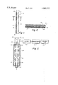
- FIG. 1 is a schematic drawing of a plate electrode in accordance with this invention
- FIG. 2 is a cross-section through lines 2--2 of FIG. 1;
- FIG. 3 is a schematic view of a flow-through disinfecting electrolytic reactor.
- the electrode 10 is generally a rectangular plate member having a thickness from about 0.3 to 2.5 cm (1/30 to 1.0 inch) and a length and width from 2.5 to 30 cm (1 to 12 inches) for use in a flow-through disinfection reactor. Large plates can be used for larger capacity reactors and smaller and shaped configurations can be used in applications such as sterilizing contact lenses.
- the electrode comprises a plate 12 of a graphite fiber filled matrix resin having an active surface 14 for removing pathogens from the liquid electrolyte and a rear surface 16 to which is applied a conductive grid element 18 such as a metal screen adhered to the rear surface by means of a conductive paste adhesive.
- the screen is embedded in a coating 20 of resin to protect it from the corrosive effects of the liquid to be treated and a conductor 22 is connected to the screen at contact 24, suitably by soldering.
- the electrode plate is formed from a composition containing 20 to 70% by volume of graphite fibers, the remainder being oxidation and corrosion resistant binder resin forming the continous matrix for the composite.
- the matrix preferably contains 5 to 15% by weight of fine grain, conductive powder such as natural monolithic graphite or conductive carbon having a particle diameter smaller than diameter of the fiber, generally from 0.1 to 1.0 microns.
- Carbon-graphite fibers suitable for use in this invention can be prepared from organic precursors such as acrylic polymers, polyvinyl alcohol, regenerated cellulose, pitch materials including petroleum residues, asphalt and coal tars.
- organic precursors such as acrylic polymers, polyvinyl alcohol, regenerated cellulose, pitch materials including petroleum residues, asphalt and coal tars.
- Highly oriented, synthetic polymer precursors such as acrylic polymers provide higher conductivity.
- Acrylic precursors do not melt prior to pyrolytic decomposition and strength properties of graphitic fibers produced from acrylic precursors are substantially improved over regenerated cellulose based fibers.
- the electrical conductivity is approximately five times that for regenerated cellulose based fibers and the degree of graphitization is substantially increased. This results from the fact that acrylic precursors yield a graphitic type of carbon as compared to the nongraphitic type of carbon produced from cellulosic materials. Furthermore, the carbon yield is approximately 45% are compared to only 25% from rayon.
- the acrylic precursors may be homopolymers of acrylonitrile or copolymers produced by copolymerizing not less than 85% of acrylonitrile with not more then 15% of monovinyl compound such as methacrylate, methylmethacrylate, vinyl-acetate, vinylchloride, vinylidine chloride, 2-methyl-5-pyridine or the like.
- the precursor polymer cyclizes, that is, forms a six member hexagon ring similar to that found in graphite. Heating in an oxygen containing atmosphere is believed to permit oxygen to diffuse into the structure of the fiber and forms cross-links or chemical bonds between the polymer chains.
- the preoxidized fiber is processed to suitably contain between about 5 to 25% oxygen, preferably about 12 to 15% oxygen.
- the preoxidized fiber is then subjected to firing and graphitization at a temperature above about 1500 degrees C. up to about 3000 degrees C. during graphitization in inert atmosphere.
- the monofilaments are then chopped into the desired length and may be polished by tumbling before being incorporated into the resin for forming into an electrode.
- the matrix resin after being cured is resistant to the chemical and electrical environment of the electrolytic cell reactor.
- the resin can be a thermoplastic or thermosetting resin.
- Exemplary resins are polyamide, polyester, phenolic, silicone, polyimide flurocarbon, polysulfone, polyaryl, polyether, polybutadiene or epoxy resins. A portion of the resin can be impregnated onto the fibers before forming the electrode.
- the electrode can be formed by casting or molding. Usually pressure is applied during fabrication, generally during curing to remove all voids and gases and to assure that a dimensionally stable structure is prepared.
- a preferred resin is a stageable, fast curing thermosetting epoxy.
- the graphite fiber, graphite powder and curing agent are dispersed in a solution of epoxy resin in solvent. After a uniform dispersion is achieved in a mixer, the dispersion is heated to remove solvent, advance the polymer cure to increase viscosity. The dispersion is then placed in a mold and heated at a higher temperature and under pressure to form an electrode plate.
- the grid screen is then adhesively secured to the back face of the electrode plate with an adhesive paste and the lead conductor soldered to the screen, or the screen can be molded in place during electrode fabrication.
- the screen and edges of the plate may be coated with further amounts of resin which is subjected to the heat for curing.
- a conductive grid can be deposited onto the surface of the electrode by vacuum deposit or electroless coating or electrolytic means. In a different configuration the conductive element is applied to a gasket and is in intimate contact with the electrode plate.
- An epoxy resin which cures in a short time to a very chemical and oxidation resistant form is epoxidized creosol-aldehyde or phenol-formaldehyde resin or mixtures thereof.
- the wet mix for the electrode molding composition also includes 0.1 to 3% of an amine hardener such as an amine modified silane, 1 to 12% of a catalyst such as boron trifluoride, 0.5 to 5% of a mold release agent such as a metal stearate and 0.0 to 2% of a pigment or dye such as nigrosine.
- a wet mix was prepared containing the following ingredients:
- the wet mix was added to graphite fiber in a sigma mixer by pouring over fibers in the mixer and mixing until the fibers were completely wetted out. During mixing, some of the brittle graphite fiber will break down into shorter lengths.
- the length of the graphite fiber should be no more than 1/2 the thickness of the electrode plate. Furthermore, shorter lengths of fiber of less than 1/6 inch in length tend to disperse more uniformly throughout the matrix. Longer lengths tend to align parallel to the face, rather than perpendicular thereto.
- the dispersion was then placed in a 6 inch ⁇ 8 inch mold and heated at 350 degrees F. at 2000 psi for about 20 minutes to form 1/8 to 1/2 inch thick plates. Details of various experiments follow:
- the plates were tested in a protype disinfection electrolytic reactor.
- the electrodes containing pitch based fibers provided better performance since pitch based fibers have a higher carbon density and the pitch fibers have a smaller diameter.
- the best performing electrodes contained 50% graphite fiber by volume.
- Example 1 The procedure of Example 1 was repeated utilizing 5% graphite powder based on resin wet mix and utilizing 50% graphite fiber.
- the electrodes were molded into mating concave and convex shapes suitable for use as a contact lens cleaning electrolytic unit.
- the electrode 50 plates are assembled into a flow-through disinfection reactor 52 in which a plurality of plates such as 6" ⁇ 81/4" ⁇ 3/16" are connected in series through the metal grids into a stack.
- the reactor 52 has a body 56 having a first compartment for receiving anode stack 58, cathode stack 60 and a central channel 62 between the stacks 58, 60 through which electrolytic waste liquid flows from inlet 64 to outlet 66.
- the NaCl from sea water provides the electrolyte for operation of the cell. If the waste liquid does not naturally include an electrolyte, one must be added as in the contact lens cleaner discussed above.
- the liquid from holding tank 70 is processed in homogenizer 72 and filter 74 before being fed to inlet 64.
- the electrode stacks are connected to AC power source 76. When switch is turned on, the reactor will disinfect urine rich liquid from which fecal solids have been removed with 30 watts of power. Ablation of the electrode faces proceeds in a controlled manner at the rate of only 1 mil per hour.
- the electrodes of the invention will also find use as dimensionally stable anodes for chlorine recovery, electrolysis of water, purification of potable water, disinfection of heat exchanger or cooling tower water, anodes for electroplating and the like.
Abstract
Improved graphite composite electrodes are provided by rendering the matrix resin conductive by dispersing therein 5 to 15% by weight of a conductive pigment and by uniformly dispersing therein randomly oriented graphite fibers having a diameter below 30 microns and a length no more than 1/2 the thickness of the electrode plate. The electrodes are particularly useful in the disinfection of aqueous liquids with low power consumption and with very low ablation of the surface of the electrode.
Description
Recently enacted environmental regulations require the disinfection of many liquids before discharge into surface streams. By 1985, the United States Environmental Protection Agency will require shipboard disinfection of all waste water. Other waters requiring disinfection are potable waters, cooling and process waters to control algae growth, hospital nebulizers and contact lens cleaning liquids. Thermal and chemical forms of disinfection and sterilizations are not suitable to most of these uses due to high cost of treatment and energy, and requirements are not suitable for small scale uses.
Electrochemical disinfecting systems have been utilized in the past. The electrodes generally utilized were metal, carbon, graphite or resin impregnated carbon-graphite. These electrodes tend to roughen, foul or deteriorate causing very short service time before requiring cleanup or replacement. Furthermore, these electrochemical systems consume large amounts of electrical power to produce the high field strengths necessary for killing the micro-organisms present in the feed water.
Graphite is desirable electrode material since it can readily and reproducibly be prepared in a low surface area form (pyrolitic or vitreous carbon) and it is stable at anodic potentials where mercury is not useable and all but the noble metals corrode rapidly. Graphite electrodes are also inexpensive and comparatively non-toxic.
Bulk graphite has been employed as an electrode as a support for immobilized enzyme catalysts or to electrochemically regenerate coenzymes such as NaDH-NaD+. They have also been employed occasionally in anodic polarography for analytical purposes. Composite electrodes based on bulk or powered graphite have been used commercially. Resin filled graphite anodes were extensively utilized in the chlor-alkali industry until the development of the titanium dimensionally stable anode (DSA). The graphite anodes had a short life. Five pounds of carbon anode were lost per ton of chlorine produced due to the anodic oxidation of bulk graphite at the comparatively high densities employed in the chlorine caustic cells. Porous graphite electrodes are prepared by sintering into a screen a slurry of graphite, metallic catalyst and particulate hydrophobic polymer.
Fiber reinforced composite materials due to the low weight and high strength are replacing structural metal components in many applications, especially in aircraft and automobiles. Though boron, glass and graphite fibers have been utilized as reinforcement for the binder resins, only graphite is conductive. A typical composite containing 40 to 60% of randomly oriented graphite fibers will have a specific resisivity of 1 to 10 ohm-cm, high enough to be considered for use as an electrode material. Since the fibers are discrete they can function as an array of microelectrodes, each functioning as a point source for reaction.
There has been no reported commercial use of graphite fiber-polymer composites as electrodes. There have been several studies concerned with the electrochemical oxidation of graphite fibers influencing wettability, adhesion and absorption of organic and inorganic substances, but there was no employment of composites as electrodes. One study of graphite fibers as electrodes was concerned with interlaminar shear strength and wettability (Dietz, et al., J. Materials Science, 6 (1971), P. 1441).
Recently, graphite composite electrodes have been tested in prototype experimental electrochemical disinfection and potable waters systems. The disinfection reactor operates as a flow-through five plate, four cell, bipolar stack using 30 watts of power to treat influent flow of waste water containing up to 150 p.p.m. of solids. This is a considerable savings of energy, safety and space as compared to chemical disinfection of sewage. Disinfection is improved three-fold over previously studied reactors with resin filled graphite or bulk graphite electrodes. The potable water reactor is also a flow-through, bipolar reactor.
The lifetime of these reactor systems is governed by the physical and electrochemical stability of the electrode plates which must withstand both anodic and cathodic electrolysis in a sea water or sewage environment. Power consumption is governed by compositional and form factors such as the type, size and distribution of the graphite fibers. Though the experimental reactors are demonstrating promising lifetimes and efficiencies, electrodes are subject to deterioration and power consumption has been higher than desired. Furthermore, the kill time for micro-organisms was not optimum nor was the mechanism understood.
Graphite composite electrodes having improved performance are provided in accordance with this invention. The length and diameter and resistivity of the discrete fibers has been optimized. Though the use of discrete randomly oriented fibers creates a multitude of localized sites for generating disinfecting species, it does not provide a continuous conduction path through the bulk of the electrode. It has further been discovered that the addition of fine, particulate conductive filler to the matrix resin improves kill efficiency and lowers power consumption.
In one form of electrolytic sewage treatment cell an AC square wave is utilized. At low voltage and power, a transient high field is generated which creates a chemical species in the saline solution, probably chlorine, which kills the micro-organisms. The rising voltage is out of phase with the current and is reversed before the electrodes can be damaged. The field strength is enhanced by use of small fibers having a diameter from about 1 to 30 microns, a length from 25 to 6250 microns (1 to 250 mils), preferably 500 to 1500 microns (20 to 60 mils). Higher conductivity fiber is also preferred to enhance field strength which can be controlled by selection of precursor, and firing temperature of precursor during graphitization. Addition of powered graphite to the matrix resin enhances dielectric constant which increases phase displacement. The use of oxidation resistant binder resins has also contributed to significantly increased service life of over several hundred hours. A prototype flow-through cell is capable of disinfecting a urine rich liquid with 2 amperes of current at 15 volts peak voltage using the power consumption of a 30 watt light bulb.
These and many other advantages and attendant features of the invention will become apparent as the the invention becomes better understood by reference to the following detailed description.
FIG. 1 is a schematic drawing of a plate electrode in accordance with this invention;
FIG. 2 is a cross-section through lines 2--2 of FIG. 1; and
FIG. 3 is a schematic view of a flow-through disinfecting electrolytic reactor.
Referring now to FIGS. 1 and 2, the electrode 10 is generally a rectangular plate member having a thickness from about 0.3 to 2.5 cm (1/30 to 1.0 inch) and a length and width from 2.5 to 30 cm (1 to 12 inches) for use in a flow-through disinfection reactor. Large plates can be used for larger capacity reactors and smaller and shaped configurations can be used in applications such as sterilizing contact lenses. The electrode comprises a plate 12 of a graphite fiber filled matrix resin having an active surface 14 for removing pathogens from the liquid electrolyte and a rear surface 16 to which is applied a conductive grid element 18 such as a metal screen adhered to the rear surface by means of a conductive paste adhesive. The screen is embedded in a coating 20 of resin to protect it from the corrosive effects of the liquid to be treated and a conductor 22 is connected to the screen at contact 24, suitably by soldering.
The electrode plate is formed from a composition containing 20 to 70% by volume of graphite fibers, the remainder being oxidation and corrosion resistant binder resin forming the continous matrix for the composite. The matrix preferably contains 5 to 15% by weight of fine grain, conductive powder such as natural monolithic graphite or conductive carbon having a particle diameter smaller than diameter of the fiber, generally from 0.1 to 1.0 microns.
Carbon-graphite fibers suitable for use in this invention can be prepared from organic precursors such as acrylic polymers, polyvinyl alcohol, regenerated cellulose, pitch materials including petroleum residues, asphalt and coal tars. Highly oriented, synthetic polymer precursors such as acrylic polymers provide higher conductivity. Acrylic precursors do not melt prior to pyrolytic decomposition and strength properties of graphitic fibers produced from acrylic precursors are substantially improved over regenerated cellulose based fibers.
The electrical conductivity is approximately five times that for regenerated cellulose based fibers and the degree of graphitization is substantially increased. This results from the fact that acrylic precursors yield a graphitic type of carbon as compared to the nongraphitic type of carbon produced from cellulosic materials. Furthermore, the carbon yield is approximately 45% are compared to only 25% from rayon.
The acrylic precursors may be homopolymers of acrylonitrile or copolymers produced by copolymerizing not less than 85% of acrylonitrile with not more then 15% of monovinyl compound such as methacrylate, methylmethacrylate, vinyl-acetate, vinylchloride, vinylidine chloride, 2-methyl-5-pyridine or the like.
Under application of heat, the precursor polymer cyclizes, that is, forms a six member hexagon ring similar to that found in graphite. Heating in an oxygen containing atmosphere is believed to permit oxygen to diffuse into the structure of the fiber and forms cross-links or chemical bonds between the polymer chains.
The preoxidized fiber is processed to suitably contain between about 5 to 25% oxygen, preferably about 12 to 15% oxygen. The preoxidized fiber is then subjected to firing and graphitization at a temperature above about 1500 degrees C. up to about 3000 degrees C. during graphitization in inert atmosphere.
The monofilaments are then chopped into the desired length and may be polished by tumbling before being incorporated into the resin for forming into an electrode. The matrix resin after being cured is resistant to the chemical and electrical environment of the electrolytic cell reactor. The resin can be a thermoplastic or thermosetting resin. Exemplary resins are polyamide, polyester, phenolic, silicone, polyimide flurocarbon, polysulfone, polyaryl, polyether, polybutadiene or epoxy resins. A portion of the resin can be impregnated onto the fibers before forming the electrode.
The electrode can be formed by casting or molding. Usually pressure is applied during fabrication, generally during curing to remove all voids and gases and to assure that a dimensionally stable structure is prepared. A preferred resin is a stageable, fast curing thermosetting epoxy. The graphite fiber, graphite powder and curing agent are dispersed in a solution of epoxy resin in solvent. After a uniform dispersion is achieved in a mixer, the dispersion is heated to remove solvent, advance the polymer cure to increase viscosity. The dispersion is then placed in a mold and heated at a higher temperature and under pressure to form an electrode plate. The grid screen is then adhesively secured to the back face of the electrode plate with an adhesive paste and the lead conductor soldered to the screen, or the screen can be molded in place during electrode fabrication. The screen and edges of the plate may be coated with further amounts of resin which is subjected to the heat for curing. Alternatively, a conductive grid can be deposited onto the surface of the electrode by vacuum deposit or electroless coating or electrolytic means. In a different configuration the conductive element is applied to a gasket and is in intimate contact with the electrode plate.
An epoxy resin which cures in a short time to a very chemical and oxidation resistant form is epoxidized creosol-aldehyde or phenol-formaldehyde resin or mixtures thereof. The wet mix for the electrode molding composition also includes 0.1 to 3% of an amine hardener such as an amine modified silane, 1 to 12% of a catalyst such as boron trifluoride, 0.5 to 5% of a mold release agent such as a metal stearate and 0.0 to 2% of a pigment or dye such as nigrosine.
A wet mix was prepared containing the following ingredients:
______________________________________
Ingredients           Parts, By Weight
______________________________________
Epoxidized creosolaldehyde resin
                      900
Epoxidized phenolaldehyde resin
                      168
Diamine coupling agent
                      12.0
Boron trifluoride     96.0
Zinc stearate         18.0
Nigrosine             6.0
Flaked graphite (0.5 micron)
                      120.00
______________________________________
The wet mix was added to graphite fiber in a sigma mixer by pouring over fibers in the mixer and mixing until the fibers were completely wetted out. During mixing, some of the brittle graphite fiber will break down into shorter lengths. The length of the graphite fiber should be no more than 1/2 the thickness of the electrode plate. Furthermore, shorter lengths of fiber of less than 1/6 inch in length tend to disperse more uniformly throughout the matrix. Longer lengths tend to align parallel to the face, rather than perpendicular thereto. The dispersion was then placed in a 6 inch×8 inch mold and heated at 350 degrees F. at 2000 psi for about 20 minutes to form 1/8 to 1/2 inch thick plates. Details of various experiments follow:
              TABLE 1
______________________________________
Fiber   Diameter Length    % Fiber  Thickness of
Precursor
        Micron   Inches    By Volume
                                    Plates, Inches
______________________________________
Pitch   3-20     1/8       50       1/4
"       "        1/16      30       3/16
"                          40       "
"                          50       "
"                          60       "
                           70       "
PAN     9-11     1/8       50       3/6
______________________________________
The plates were tested in a protype disinfection electrolytic reactor. The electrodes containing pitch based fibers provided better performance since pitch based fibers have a higher carbon density and the pitch fibers have a smaller diameter. The best performing electrodes contained 50% graphite fiber by volume.
The procedure of Example 1 was repeated utilizing 5% graphite powder based on resin wet mix and utilizing 50% graphite fiber. The electrodes were molded into mating concave and convex shapes suitable for use as a contact lens cleaning electrolytic unit.
Referring now to FIG. 3, the electrode 50 plates are assembled into a flow-through disinfection reactor 52 in which a plurality of plates such as 6"×81/4"×3/16" are connected in series through the metal grids into a stack. The reactor 52 has a body 56 having a first compartment for receiving anode stack 58, cathode stack 60 and a central channel 62 between the stacks 58, 60 through which electrolytic waste liquid flows from inlet 64 to outlet 66. The NaCl from sea water provides the electrolyte for operation of the cell. If the waste liquid does not naturally include an electrolyte, one must be added as in the contact lens cleaner discussed above.
The liquid from holding tank 70 is processed in homogenizer 72 and filter 74 before being fed to inlet 64. The electrode stacks are connected to AC power source 76. When switch is turned on, the reactor will disinfect urine rich liquid from which fecal solids have been removed with 30 watts of power. Ablation of the electrode faces proceeds in a controlled manner at the rate of only 1 mil per hour.
The electrodes of the invention will also find use as dimensionally stable anodes for chlorine recovery, electrolysis of water, purification of potable water, disinfection of heat exchanger or cooling tower water, anodes for electroplating and the like.
It is to be realized that only preferred embodiments of the invention have been described and that numerous substitutions, modifications and alterations are permissible without departing from the spirit and scope of the invention as defined in the following claims.
Claims (20)
1. An electrode comprising a shaped member having an electrode face and a rear face defining a thickness, said electrode comprising a composite of a uniform dispersion of randomly distributed graphite fibers having a diameter from 1 to 30 microns and a length of no more than 1/2 the thickness of the electrode member dispersed in a cured, oxidation-resistant and chemical resistant, continuous matrix resin containing a dispersion of conductive particles selected from graphite and carbon having a diameter smaller than the diameter of the fibers.
2. An electrode according to claim 1 in which the particles have a diameter of from 0.1 to 1 micron.
3. An electrode according to claim 2 in which the particles are graphite flake.
4. An electrode according to claim 3 in which the graphite fiber has a diameter from 3 to 22 microns.
5. An electrode according to claim 4 in which the graphite fiber is a pitch based fiber.
6. An electrode according to claim 5 in which the matrix resin is an oxidation and chemical resistant thermosetting resin.
7. An electrode according to claim 6 in which the resin is an epoxy resin.
8. An electrode according to claim 7 in which the epoxy resin comprises an epoxidized aromatic alcohol-aldehyde prepolymer resin.
9. An electrode according to claim 8 in which the epoxy resin contains a cured mixture of epoxidized creosol-aldehyde and phenol-aldehyde prepolymer resins.
10. An electrode according to claim 1 further including a metal conductive element applied to the rear surface thereof.
11. An electrode according to claim 10 in which the element is a metal screen grid.
12. An electrode according to claim 11 in which the screen grid is adhesively secured to the rear face.
13. An electrode according to claim 10 in which the element is electrodeposited onto the rear face of the electrode.
14. An electrode according to claim 1 in which the member is in the shape is of a flat plate.
15. An electrode according to claim 1 in which the fibers have a length from 25 to 6250 microns.
16. An electrolytic cell comprising in combination:
walls defining a housing having a compartment for receiving a body of electrolyte,
an anode electrode within the housing having a front face in a communication with the compartment and having a rear face,
a cathode electrode within the housing having a front face in a communication with the compartment and having a rear face,
contact means for connection to the rear faces of said electrodes, and
at least one of said electrodes comprising a composite of a uniform dispersion of randomly distributed graphite fibers having a diameter from 1 to 30 micron and a length no more than 1/2 the thickness of the electrode dispersed in a cured, oxidation and chemical resistant, continuous, matrix resin containing a dispersion of fine, particulate conductive filler having a diameter less than the diameter of the fibers and selected from carbon or graphite.
17. A cell according to claim 16 in which the composite electrode includes a plurality of the flat shaped members connected in series in a stack.
18. A cell according to claim 17 in which the conductive filler is graphite or carbon having a diameter from 0.1 to 1 micron, and the graphite fiber is a pitch based fiber having a diameter from 3 to 22 microns and a length of no more than half the thickness of the plate and the plate has a thickness from 1/8 to 1/2 inch.
19. A cell according to claim 16 in which the matrix resin is an oxidation and chemically resistant epoxy resin.
20. A cell according to claim 19 in which the epoxy resin comprises a mixture of cured epoxidized creosolaldehyde and phenol aldehyde resins.
Priority Applications (1)
| Application Number | Priority Date | Filing Date | Title |
|---|---|---|---|
| US06/087,206 US4265727A (en) | 1979-10-22 | 1979-10-22 | Composite electrodes |
Applications Claiming Priority (1)
| Application Number | Priority Date | Filing Date | Title |
|---|---|---|---|
| US06/087,206 US4265727A (en) | 1979-10-22 | 1979-10-22 | Composite electrodes |
Publications (1)
| Publication Number | Publication Date |
|---|---|
| US4265727A true US4265727A (en) | 1981-05-05 |
Family
ID=22203729
Family Applications (1)
| Application Number | Title | Priority Date | Filing Date |
|---|---|---|---|
| US06/087,206 Expired - Lifetime US4265727A (en) | 1979-10-22 | 1979-10-22 | Composite electrodes |
Country Status (1)
| Country | Link |
|---|---|
| US (1) | US4265727A (en) |
Cited By (36)
| Publication number | Priority date | Publication date | Assignee | Title |
|---|---|---|---|---|
| US4330387A (en) * | 1979-12-18 | 1982-05-18 | Societe Nationale Elf Aquitaine | Modified carbon or graphite fibrous percolating porous electrode, and electrochemical reactors fitted with such an electrode |
| US4333813A (en) * | 1980-03-03 | 1982-06-08 | Reynolds Metals Company | Cathodes for alumina reduction cells |
| US4339322A (en) * | 1980-04-21 | 1982-07-13 | General Electric Company | Carbon fiber reinforced fluorocarbon-graphite bipolar current collector-separator |
| US4401519A (en) * | 1981-02-25 | 1983-08-30 | Olin Corporation | Method for producing reticulate electrode for electrolytic cells |
| US4439303A (en) * | 1982-06-28 | 1984-03-27 | Maurice Cocchi | Crystallographically-oriented spatially-dispersed conductive fiber electrode |
| US4512858A (en) * | 1983-02-19 | 1985-04-23 | Kernforschungsanlage Julich Gesellschaft Mit Beschrankter Haftung | Method of producing an electrode usable as a flow-through anode |
| US4549912A (en) * | 1981-06-11 | 1985-10-29 | General Electric Company | Anode and cathode connections for the practice of electromigration |
| US4564427A (en) * | 1984-12-24 | 1986-01-14 | United Technologies Corporation | Circulating electrolyte electrochemical cell having gas depolarized cathode with hydrophobic barrier layer |
| US4565619A (en) * | 1983-02-18 | 1986-01-21 | The Foxboro Company | Composite electrode structure |
| EP0199493A1 (en) * | 1985-04-18 | 1986-10-29 | Imperial Chemical Industries Plc | Electrode for electrochemical cell |
| WO1987000559A1 (en) * | 1985-07-15 | 1987-01-29 | Terry Roy Jackson | Electrode construction |
| US4647359A (en) * | 1985-10-16 | 1987-03-03 | Prototech Company | Electrocatalytic gas diffusion electrode employing thin carbon cloth layer |
| US4687997A (en) * | 1984-06-22 | 1987-08-18 | Coopervision, Inc. | Container with safety features for cleansing medical devices |
| EP0244626A1 (en) * | 1986-03-27 | 1987-11-11 | Wessling, Bernhard, Dr. | Electrode and its use |
| US4743349A (en) * | 1983-06-22 | 1988-05-10 | Atochem | Electrically conductive fibrous web substrate and cathodic element comprised thereof |
| US4761216A (en) * | 1987-04-01 | 1988-08-02 | Olin Corporation | Multilayer electrode |
| US4774029A (en) * | 1985-11-18 | 1988-09-27 | Skeptikos Technology, Inc. | Conductive polymers and method of preparation thereof |
| US4941961A (en) * | 1988-04-21 | 1990-07-17 | Mitsuboshi Belting Ltd. | Flexible elastomer electrode |
| US4990581A (en) * | 1988-03-10 | 1991-02-05 | Skeptikos Technology, Inc. | Conductive polymers and method of preparation thereof |
| USRE34233E (en) * | 1983-06-22 | 1993-04-27 | Atochem | Electrically conductive fibrous web substrate and cathodic element comprised thereof |
| US5238672A (en) * | 1989-06-20 | 1993-08-24 | Ashland Oil, Inc. | Mesophase pitches, carbon fiber precursors, and carbonized fibers |
| US6248467B1 (en) | 1998-10-23 | 2001-06-19 | The Regents Of The University Of California | Composite bipolar plate for electrochemical cells |
| GB2367072A (en) * | 2000-03-22 | 2002-03-27 | Univ Brunel | Mineraliser reaction cell for purifying liquids |
| US20020155333A1 (en) * | 2001-01-19 | 2002-10-24 | Fitts Bruce B. | Apparatus and method for electrochemical cell components |
| US20030221971A1 (en) * | 2002-06-04 | 2003-12-04 | Keister Timothy Edward | Method for electrolytic production of hypobromite for use as a biocide |
| US20040076863A1 (en) * | 2001-01-19 | 2004-04-22 | Baars Dirk M. | Apparatus and method of manufacture of electrochemical cell components |
| US6811917B2 (en) | 2000-08-14 | 2004-11-02 | World Properties, Inc. | Thermosetting composition for electrochemical cell components and methods of making thereof |
| US7172734B1 (en) * | 2000-06-26 | 2007-02-06 | Joshi Ashok V | Sanitizing device and associated method |
| US20070141434A1 (en) * | 2000-06-26 | 2007-06-21 | Joshi Ashok V | Sanitizing Device and Associated Method Using Electrochemically Produced Sanitizing Agents |
| US20070246352A1 (en) * | 2002-06-04 | 2007-10-25 | Prochem Tech International, Inc. | Flow-through-resin-impregnated monolithic graphite electrode and containerless electrolytic cell comprising same |
| EP2015384A1 (en) | 2007-06-15 | 2009-01-14 | TUBITAK-Turkiye Bilimsel ve Teknolojik ve Arastima Kurumu | A method for producing recyclable bipolar plate |
| US20110013342A1 (en) * | 2008-03-25 | 2011-01-20 | Tokyo University Of Science Educational Foundation Administrative Organization | Method for producing dielectric film and method for producing capacitor layer-forming material using the method for producing dielectric film |
| US20110174633A1 (en) * | 2002-06-04 | 2011-07-21 | Prochemtech International, Inc. | Flow-through-resin-impregnated monolithic graphite electrode and containerless electrolytic cell comprising same |
| WO2012028052A1 (en) * | 2010-08-30 | 2012-03-08 | Jiang Yaxi | Transition board of eft inert composite electrode, preparation method thereof and electrolytic apparatus including the same |
| WO2012028055A1 (en) * | 2010-08-30 | 2012-03-08 | Jiang Yaxi | Cathode plate for eft inert composite electrode, preparation method therefor and electrolysis equipment containing same |
| US20120177934A1 (en) * | 2009-07-22 | 2012-07-12 | Bayer MaterialScience AG Law and Patents | Method for the production of stretchable electrodes |
Citations (7)
| Publication number | Priority date | Publication date | Assignee | Title |
|---|---|---|---|---|
| GB1147853A (en) * | 1966-10-12 | 1969-04-10 | Rhein Westfael Elect Werk Ag | Improvements in and relating to graphite fibre plaques and the like for electrochemical cells |
| BE765864A (en) * | 1970-04-17 | 1971-09-16 | Kureha Chemical Ind Co Ltd | PROCESS FOR MANUFACTURING PLATES OF ELECTROLYTIC ANODES |
| JPS4825567A (en) * | 1971-08-05 | 1973-04-03 | ||
| GB1434824A (en) * | 1972-11-10 | 1976-05-05 | Coal Industry Patents Ltd | Carbon artifacts |
| US4046663A (en) * | 1974-08-07 | 1977-09-06 | 308489 Ontario Limited | Carbon fiber electrode |
| US4130473A (en) * | 1976-03-05 | 1978-12-19 | Eddleman William L | Electrode structure for use in metal in exchange apparatus useful in purifying spent acids and the like |
| US4197180A (en) * | 1977-03-10 | 1980-04-08 | Courtaulds Limited | Separating solids from liquids |
-
1979
- 1979-10-22 US US06/087,206 patent/US4265727A/en not_active Expired - Lifetime
Patent Citations (7)
| Publication number | Priority date | Publication date | Assignee | Title |
|---|---|---|---|---|
| GB1147853A (en) * | 1966-10-12 | 1969-04-10 | Rhein Westfael Elect Werk Ag | Improvements in and relating to graphite fibre plaques and the like for electrochemical cells |
| BE765864A (en) * | 1970-04-17 | 1971-09-16 | Kureha Chemical Ind Co Ltd | PROCESS FOR MANUFACTURING PLATES OF ELECTROLYTIC ANODES |
| JPS4825567A (en) * | 1971-08-05 | 1973-04-03 | ||
| GB1434824A (en) * | 1972-11-10 | 1976-05-05 | Coal Industry Patents Ltd | Carbon artifacts |
| US4046663A (en) * | 1974-08-07 | 1977-09-06 | 308489 Ontario Limited | Carbon fiber electrode |
| US4130473A (en) * | 1976-03-05 | 1978-12-19 | Eddleman William L | Electrode structure for use in metal in exchange apparatus useful in purifying spent acids and the like |
| US4197180A (en) * | 1977-03-10 | 1980-04-08 | Courtaulds Limited | Separating solids from liquids |
Cited By (44)
| Publication number | Priority date | Publication date | Assignee | Title |
|---|---|---|---|---|
| US4330387A (en) * | 1979-12-18 | 1982-05-18 | Societe Nationale Elf Aquitaine | Modified carbon or graphite fibrous percolating porous electrode, and electrochemical reactors fitted with such an electrode |
| US4333813A (en) * | 1980-03-03 | 1982-06-08 | Reynolds Metals Company | Cathodes for alumina reduction cells |
| US4339322A (en) * | 1980-04-21 | 1982-07-13 | General Electric Company | Carbon fiber reinforced fluorocarbon-graphite bipolar current collector-separator |
| US4401519A (en) * | 1981-02-25 | 1983-08-30 | Olin Corporation | Method for producing reticulate electrode for electrolytic cells |
| US4549912A (en) * | 1981-06-11 | 1985-10-29 | General Electric Company | Anode and cathode connections for the practice of electromigration |
| US4439303A (en) * | 1982-06-28 | 1984-03-27 | Maurice Cocchi | Crystallographically-oriented spatially-dispersed conductive fiber electrode |
| US4565619A (en) * | 1983-02-18 | 1986-01-21 | The Foxboro Company | Composite electrode structure |
| US4512858A (en) * | 1983-02-19 | 1985-04-23 | Kernforschungsanlage Julich Gesellschaft Mit Beschrankter Haftung | Method of producing an electrode usable as a flow-through anode |
| US4743349A (en) * | 1983-06-22 | 1988-05-10 | Atochem | Electrically conductive fibrous web substrate and cathodic element comprised thereof |
| USRE34233E (en) * | 1983-06-22 | 1993-04-27 | Atochem | Electrically conductive fibrous web substrate and cathodic element comprised thereof |
| US4687997A (en) * | 1984-06-22 | 1987-08-18 | Coopervision, Inc. | Container with safety features for cleansing medical devices |
| US4564427A (en) * | 1984-12-24 | 1986-01-14 | United Technologies Corporation | Circulating electrolyte electrochemical cell having gas depolarized cathode with hydrophobic barrier layer |
| US4737257A (en) * | 1985-04-18 | 1988-04-12 | Imperial Chemical Industries Plc | Electrode for electrochemical cell |
| EP0199493A1 (en) * | 1985-04-18 | 1986-10-29 | Imperial Chemical Industries Plc | Electrode for electrochemical cell |
| AU578821B2 (en) * | 1985-04-18 | 1988-11-03 | Imperial Chemical Industries Plc | Electrode for electrochemical cell |
| WO1987000559A1 (en) * | 1985-07-15 | 1987-01-29 | Terry Roy Jackson | Electrode construction |
| US4647359A (en) * | 1985-10-16 | 1987-03-03 | Prototech Company | Electrocatalytic gas diffusion electrode employing thin carbon cloth layer |
| US4774029A (en) * | 1985-11-18 | 1988-09-27 | Skeptikos Technology, Inc. | Conductive polymers and method of preparation thereof |
| EP0244626A1 (en) * | 1986-03-27 | 1987-11-11 | Wessling, Bernhard, Dr. | Electrode and its use |
| US4761216A (en) * | 1987-04-01 | 1988-08-02 | Olin Corporation | Multilayer electrode |
| US4990581A (en) * | 1988-03-10 | 1991-02-05 | Skeptikos Technology, Inc. | Conductive polymers and method of preparation thereof |
| US4941961A (en) * | 1988-04-21 | 1990-07-17 | Mitsuboshi Belting Ltd. | Flexible elastomer electrode |
| US5238672A (en) * | 1989-06-20 | 1993-08-24 | Ashland Oil, Inc. | Mesophase pitches, carbon fiber precursors, and carbonized fibers |
| US5614164A (en) * | 1989-06-20 | 1997-03-25 | Ashland Inc. | Production of mesophase pitches, carbon fiber precursors, and carbonized fibers |
| US6248467B1 (en) | 1998-10-23 | 2001-06-19 | The Regents Of The University Of California | Composite bipolar plate for electrochemical cells |
| GB2367072A (en) * | 2000-03-22 | 2002-03-27 | Univ Brunel | Mineraliser reaction cell for purifying liquids |
| US20070141434A1 (en) * | 2000-06-26 | 2007-06-21 | Joshi Ashok V | Sanitizing Device and Associated Method Using Electrochemically Produced Sanitizing Agents |
| US7172734B1 (en) * | 2000-06-26 | 2007-02-06 | Joshi Ashok V | Sanitizing device and associated method |
| US6811917B2 (en) | 2000-08-14 | 2004-11-02 | World Properties, Inc. | Thermosetting composition for electrochemical cell components and methods of making thereof |
| US7138203B2 (en) | 2001-01-19 | 2006-11-21 | World Properties, Inc. | Apparatus and method of manufacture of electrochemical cell components |
| US20020155333A1 (en) * | 2001-01-19 | 2002-10-24 | Fitts Bruce B. | Apparatus and method for electrochemical cell components |
| US20040076863A1 (en) * | 2001-01-19 | 2004-04-22 | Baars Dirk M. | Apparatus and method of manufacture of electrochemical cell components |
| WO2003102270A1 (en) * | 2002-06-04 | 2003-12-11 | Prochemtech International, Inc. | Method for electrolytic production of hypobromite for use as a biocide |
| US20050263404A1 (en) * | 2002-06-04 | 2005-12-01 | Prochemtech International, Inc. | Method for electrolytic production of hypobromite for use as a biocide |
| US20030221971A1 (en) * | 2002-06-04 | 2003-12-04 | Keister Timothy Edward | Method for electrolytic production of hypobromite for use as a biocide |
| US20070246352A1 (en) * | 2002-06-04 | 2007-10-25 | Prochem Tech International, Inc. | Flow-through-resin-impregnated monolithic graphite electrode and containerless electrolytic cell comprising same |
| US7927470B2 (en) | 2002-06-04 | 2011-04-19 | Prochemtech International, Inc. | Flow-through-resin-impregnated monolithic graphite electrode and containerless electrolytic cell comprising same |
| US20110174633A1 (en) * | 2002-06-04 | 2011-07-21 | Prochemtech International, Inc. | Flow-through-resin-impregnated monolithic graphite electrode and containerless electrolytic cell comprising same |
| US8585999B2 (en) * | 2002-06-04 | 2013-11-19 | Prochemtech International, Inc. | Method of making flow-through-resin-impregnated monolithic graphite electrode and containerless electrolytic cell comprising same |
| EP2015384A1 (en) | 2007-06-15 | 2009-01-14 | TUBITAK-Turkiye Bilimsel ve Teknolojik ve Arastima Kurumu | A method for producing recyclable bipolar plate |
| US20110013342A1 (en) * | 2008-03-25 | 2011-01-20 | Tokyo University Of Science Educational Foundation Administrative Organization | Method for producing dielectric film and method for producing capacitor layer-forming material using the method for producing dielectric film |
| US20120177934A1 (en) * | 2009-07-22 | 2012-07-12 | Bayer MaterialScience AG Law and Patents | Method for the production of stretchable electrodes |
| WO2012028052A1 (en) * | 2010-08-30 | 2012-03-08 | Jiang Yaxi | Transition board of eft inert composite electrode, preparation method thereof and electrolytic apparatus including the same |
| WO2012028055A1 (en) * | 2010-08-30 | 2012-03-08 | Jiang Yaxi | Cathode plate for eft inert composite electrode, preparation method therefor and electrolysis equipment containing same |
Similar Documents
| Publication | Publication Date | Title |
|---|---|---|
| US4265727A (en) | Composite electrodes | |
| US4369104A (en) | Continuous filament graphite composite electrodes | |
| AU2012267124B2 (en) | Efficient treatment of wastewater using electrochemical cell | |
| CN102648308B (en) | Ozone generating apparatus | |
| US10266429B2 (en) | Efficient treatment of wastewater using electrochemical cell | |
| CN106006860A (en) | High-salinity organic wastewater treatment device powered by solar energy | |
| AU2012267124A1 (en) | Efficient treatment of wastewater using electrochemical cell | |
| CN101423266A (en) | Wastewater treatment device of horizontal polar plate multi-electrodes electrocatalysis reactor | |
| JPH10153688A (en) | Method for processing radioactive waste liquid flow | |
| Gholizadeh et al. | Improved power density and Cr/Pb removal using ozone in a microbial desalination cell | |
| US4285796A (en) | Electrolysis electrode | |
| KR20180101434A (en) | Electrochemical cell for wastewater treatment with increased pollutant removal rate | |
| JPS58217685A (en) | Anode for electrolytic process | |
| CN102385962A (en) | Insulation particles of three-dimensional electrode reactor and preparation and application method thereof | |
| US20070246352A1 (en) | Flow-through-resin-impregnated monolithic graphite electrode and containerless electrolytic cell comprising same | |
| US8585999B2 (en) | Method of making flow-through-resin-impregnated monolithic graphite electrode and containerless electrolytic cell comprising same | |
| JP4001673B2 (en) | Porous carbon electrode for water treatment | |
| RU2182033C2 (en) | Reclaimable unit and plant for purification of liquid media | |
| US4337138A (en) | Electrolysis electrode | |
| KR20190047868A (en) | Method of manufacturing electrode for water treatment | |
| JP4656370B2 (en) | Separator for polymer electrolyte fuel cell, method for producing the same, and polymer electrolyte fuel cell | |
| JPH091151A (en) | Carbon electrode for water treatment | |
| KR100840529B1 (en) | Apparatus to Remove Electrochemically Organic Materials in Waste Water Using Electrodes | |
| CN104341026A (en) | Three-dimensional electrode electrocatalytic oxidation sewage treatment equipment | |
| CN115676982B (en) | Sewage denitrification device and method based on alternating current electrolysis |
Legal Events
| Date | Code | Title | Description |
|---|---|---|---|
| STCF | Information on status: patent grant |
Free format text: PATENTED CASE |
|
| AS | Assignment |
Owner name: CITICORP U.S.A., INC. AS AGENT, NEW YORK Free format text: SECURITY AGREEMENT;ASSIGNOR:SGL CARBON COMPOSITES, INC.;REEL/FRAME:009935/0511 Effective date: 19981217 |
|
| AS | Assignment |
Owner name: HITCO CARBON COMPOSITES, INC., CALIFORNIA Free format text: CHANGE OF NAME;ASSIGNOR:SGL CARBON COMPOSITES, INC.;REEL/FRAME:010327/0185 Effective date: 19990824 |