US4268482A - Catalytic reactor - Google Patents
Catalytic reactor Download PDFInfo
- Publication number
- US4268482A US4268482A US05/931,400 US93140078A US4268482A US 4268482 A US4268482 A US 4268482A US 93140078 A US93140078 A US 93140078A US 4268482 A US4268482 A US 4268482A
- Authority
- US
- United States
- Prior art keywords
- gas
- catalyst
- sheet
- catalysts
- reaction chamber
- Prior art date
- Legal status (The legal status is an assumption and is not a legal conclusion. Google has not performed a legal analysis and makes no representation as to the accuracy of the status listed.)
- Expired - Lifetime
Links
- 230000003197 catalytic effect Effects 0.000 title claims abstract description 42
- 239000003054 catalyst Substances 0.000 claims abstract description 144
- 230000000712 assembly Effects 0.000 claims abstract description 22
- 238000000429 assembly Methods 0.000 claims abstract description 22
- 230000000630 rising effect Effects 0.000 claims abstract description 5
- 239000007789 gas Substances 0.000 claims description 81
- 238000006243 chemical reaction Methods 0.000 claims description 14
- 238000006555 catalytic reaction Methods 0.000 claims description 7
- UGFAIRIUMAVXCW-UHFFFAOYSA-N Carbon monoxide Chemical compound [O+]#[C-] UGFAIRIUMAVXCW-UHFFFAOYSA-N 0.000 claims description 6
- 239000003546 flue gas Substances 0.000 claims description 6
- RTAQQCXQSZGOHL-UHFFFAOYSA-N Titanium Chemical compound [Ti] RTAQQCXQSZGOHL-UHFFFAOYSA-N 0.000 claims description 2
- 239000010936 titanium Substances 0.000 claims description 2
- 229910052719 titanium Inorganic materials 0.000 claims description 2
- 229910052720 vanadium Inorganic materials 0.000 claims description 2
- LEONUFNNVUYDNQ-UHFFFAOYSA-N vanadium atom Chemical compound [V] LEONUFNNVUYDNQ-UHFFFAOYSA-N 0.000 claims description 2
- QGZKDVFQNNGYKY-UHFFFAOYSA-N Ammonia Chemical compound N QGZKDVFQNNGYKY-UHFFFAOYSA-N 0.000 description 8
- 229910021529 ammonia Inorganic materials 0.000 description 4
- 230000007423 decrease Effects 0.000 description 3
- 230000007547 defect Effects 0.000 description 3
- MWUXSHHQAYIFBG-UHFFFAOYSA-N nitrogen oxide Inorganic materials O=[N] MWUXSHHQAYIFBG-UHFFFAOYSA-N 0.000 description 3
- 241000264877 Hippospongia communis Species 0.000 description 2
- 239000000428 dust Substances 0.000 description 2
- 210000003660 reticulum Anatomy 0.000 description 2
- 125000006850 spacer group Chemical group 0.000 description 2
- 239000003638 chemical reducing agent Substances 0.000 description 1
- 238000010276 construction Methods 0.000 description 1
- 230000000694 effects Effects 0.000 description 1
- 229910052751 metal Inorganic materials 0.000 description 1
- 239000002184 metal Substances 0.000 description 1
- 239000002245 particle Substances 0.000 description 1
- 230000000717 retained effect Effects 0.000 description 1
- 239000011343 solid material Substances 0.000 description 1
- 239000002699 waste material Substances 0.000 description 1
Images

Classifications
-
- B01J35/56—
-
- B—PERFORMING OPERATIONS; TRANSPORTING
- B01—PHYSICAL OR CHEMICAL PROCESSES OR APPARATUS IN GENERAL
- B01D—SEPARATION
- B01D53/00—Separation of gases or vapours; Recovering vapours of volatile solvents from gases; Chemical or biological purification of waste gases, e.g. engine exhaust gases, smoke, fumes, flue gases, aerosols
- B01D53/34—Chemical or biological purification of waste gases
- B01D53/74—General processes for purification of waste gases; Apparatus or devices specially adapted therefor
- B01D53/86—Catalytic processes
- B01D53/8621—Removing nitrogen compounds
- B01D53/8625—Nitrogen oxides
- B01D53/8631—Processes characterised by a specific device
-
- B—PERFORMING OPERATIONS; TRANSPORTING
- B01—PHYSICAL OR CHEMICAL PROCESSES OR APPARATUS IN GENERAL
- B01J—CHEMICAL OR PHYSICAL PROCESSES, e.g. CATALYSIS OR COLLOID CHEMISTRY; THEIR RELEVANT APPARATUS
- B01J19/00—Chemical, physical or physico-chemical processes in general; Their relevant apparatus
- B01J19/32—Packing elements in the form of grids or built-up elements for forming a unit or module inside the apparatus for mass or heat transfer
-
- B—PERFORMING OPERATIONS; TRANSPORTING
- B01—PHYSICAL OR CHEMICAL PROCESSES OR APPARATUS IN GENERAL
- B01J—CHEMICAL OR PHYSICAL PROCESSES, e.g. CATALYSIS OR COLLOID CHEMISTRY; THEIR RELEVANT APPARATUS
- B01J2219/00—Chemical, physical or physico-chemical processes in general; Their relevant apparatus
- B01J2219/32—Details relating to packing elements in the form of grids or built-up elements for forming a unit of module inside the apparatus for mass or heat transfer
- B01J2219/322—Basic shape of the elements
- B01J2219/32203—Sheets
- B01J2219/32206—Flat sheets
-
- B—PERFORMING OPERATIONS; TRANSPORTING
- B01—PHYSICAL OR CHEMICAL PROCESSES OR APPARATUS IN GENERAL
- B01J—CHEMICAL OR PHYSICAL PROCESSES, e.g. CATALYSIS OR COLLOID CHEMISTRY; THEIR RELEVANT APPARATUS
- B01J2219/00—Chemical, physical or physico-chemical processes in general; Their relevant apparatus
- B01J2219/32—Details relating to packing elements in the form of grids or built-up elements for forming a unit of module inside the apparatus for mass or heat transfer
- B01J2219/322—Basic shape of the elements
- B01J2219/32203—Sheets
- B01J2219/32213—Plurality of essentially parallel sheets
-
- B—PERFORMING OPERATIONS; TRANSPORTING
- B01—PHYSICAL OR CHEMICAL PROCESSES OR APPARATUS IN GENERAL
- B01J—CHEMICAL OR PHYSICAL PROCESSES, e.g. CATALYSIS OR COLLOID CHEMISTRY; THEIR RELEVANT APPARATUS
- B01J2219/00—Chemical, physical or physico-chemical processes in general; Their relevant apparatus
- B01J2219/32—Details relating to packing elements in the form of grids or built-up elements for forming a unit of module inside the apparatus for mass or heat transfer
- B01J2219/322—Basic shape of the elements
- B01J2219/32203—Sheets
- B01J2219/32224—Sheets characterised by the orientation of the sheet
- B01J2219/32227—Vertical orientation
-
- B—PERFORMING OPERATIONS; TRANSPORTING
- B01—PHYSICAL OR CHEMICAL PROCESSES OR APPARATUS IN GENERAL
- B01J—CHEMICAL OR PHYSICAL PROCESSES, e.g. CATALYSIS OR COLLOID CHEMISTRY; THEIR RELEVANT APPARATUS
- B01J2219/00—Chemical, physical or physico-chemical processes in general; Their relevant apparatus
- B01J2219/32—Details relating to packing elements in the form of grids or built-up elements for forming a unit of module inside the apparatus for mass or heat transfer
- B01J2219/324—Composition or microstructure of the elements
- B01J2219/32466—Composition or microstructure of the elements comprising catalytically active material
Definitions
- This invention relates to a catalytic reactor, particularly to an arrangement of catalyst in the catalytic reactor which is suitable for treatment of a gas including a lot of dusts.
- An object of the invention is to provide a catalytic reactor in which catalyst is arranged such that a gas to be treated can be contacted with the catalyst well enough without increasing drafting resistance, and the catalyst is not lost to any great extent.
- Another object of the invention is to provide a catalytic reactor of simple construction in which catalyst is arranged such that a gas to be treated can be contacted with the catalyst well enough without increasing draft resistance.
- a feature of the invention is that a plurality of catalyst groups, each including a plurality of sheet catalysts arranged in parallel to each other with distances therebetween, are stacked in a catalytic reactor so that leading edges of the sheet catalysts of each of the catalyst groups are exposed to the gas rising in the catalytic reactor.
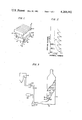
- FIG. 1 is a perspective view showing a sheet catalyst arrangement according to the present invention
- FIG. 2 is a graph showing a relation between Sherwood number and a vertical distance (x) of the sheet catalyst arrangement shown in FIG. 1;
- FIG. 3 is a partially sectional view of an embodiment of a catalytic reactor according to the invention.
- FIG. 4 is a plane view of a catalyst assembly adapted in the catalytic reactor of FIG. 3;
- FIG. 5 is a section view of the catalyst assembly taken along a line V--V in FIG. 4;
- FIG. 6 is a graph showing relations between gas pressures ⁇ P and length L of each of a plurality of sheet catalysts.
- FIG. 7 is a graph showing a relation between mass transfer coefficient of a gas and the length L.
- FIGS. 1 and 2 First, an embodiment of a catalyst arrangement according to the invention will be explained hereinafter, referring to FIGS. 1 and 2.
- a plurality of catalyst groups 1, 2 are stacked along a gas flow 3.
- the catalyst groups 1, 2 each comprises a plurality of sheet catalysts 4, 5 each arranged in parallel to each other with distances B therebetween.
- Each of the sheet catalysts 4, 5 has width W, a length L and a leading edge 6 or 7.
- the catalyst group 2 is stacked on the catalyst group 1 so that the length directions of the sheet catalysts 4, 5 will be in the gas flow 3, and a plurality of the leading edges 6, 7 of the sheet catalysts 4, 5 of the catalyst groups 1, 2 will be exposed to the gas flow 3, preferably so that the width directions of the sheet catalysts of one 1 of the catalyst groups 1, 2 will traverse the width directions of the immediately adjacent one 2 of the catalyst groups 1, 2.
- the gas 3 to be treated enters the plurality of catalyst groups 1, 2 at their bottom and passes upward through a plurality of gas passages defined by the sheet catalysts 4, 5.
- the gas contacts with the side surfaces of the gas passages or the sheet catalysts 4, 5 while passing upward.
- a magnitude of mass transfer rate of the gas 3 is expressed by the Sherwood number (Sh).
- Sh Sherwood number
- the condition of the contact of the gas 3 and the sheet catalysts 4, 5 will be explained hereinafter in detail, using Sh and referring to FIG. 2.
- the length L of the sheet catalyst 4, 5 is proper. According to experimental results as shown in FIGS. 6 and 7, the length L, which is influenced by a distance B (m) between the sheet catalysts and a gas flow rate Ug (m/s), is given as follows:
- curves E, F and G show relations between pressure losses ⁇ P (mm Aq/m) and the length L (mm), when sheet catalysts of various length L are arranged as shown in FIG. 1, with distances B of 0.01 m therebetween, and when a gas is introduced into the sheet catalyst arrangement at velocities of 8.5 m/s (curve E), 10 m/s (curve F), and 12.5 m/s (curve G).
- FIG. 7 there is shown a curve I expressing a relation between mass transfer coefficient kf (m/h) and the length L of the sheet catalyst, when the sheet catalyst is of various length L, and arranged as shown in FIG. 1 with the distance B of 0.01 m therebetween, and when a gas is introduced into the sheet catalyst arrangement at a velocity of 10 m/s.
- the mass transfer coefficient does not increase where the length L is longer than 300 mm. Based on the relation, the upper limit of the length L is determined so that the other values of the distance B and the gas velocity Ug will be adapted. Therefore, when the length L is too large to meet the above equation, high Sh can not be expected, so that a sufficient catalytic reaction will not be effected.
- an undulating plate catalyst a sheet-shaped plate catalyst formed of a gas permeable catalyst carrier such as a wire net carrying thereon catalyst particles, or the like may be used.
- FIG. 3 shows a denitration apparatus in which nitrogen oxides in a waste flue gas from a boiler is made harmless by using ammonia as a reducing agent.
- a catalytic reactor 11 communicates with a boiler 13 through a flue 15.
- a plurality of catalyst assemblies 17, 19 are stacked, and one end of the flue 15 is provided between the lowest catalyst assembly 17 and the bottom 21 of the catalytic reactor 11.
- the flue 15 is provided with a dust collector 23, a container 25 for ammonia, and a blower 27.
- a flue gas to be treated from the boiler 13 is introduced into the lower portion of the catalytic reactor 11, rises upward passing through the catalyst assemblies 17, 19 and goes out of the catalytic reactor 11, which flue gas has had dusts removed therefrom by the dust collector 23, and ammonia injected from the container 25, before reaching the blower 27, and the flue gas mixed with ammonia contacts with catalyst to effect catalytic reaction while rising through the catalyst assemblies 17, 19.
- the catalyst assemblies 17, 19 each are constructed as shown in FIGS. 4 and 5.
- a frame 29 is square and provided with retaining portions 31.
- a plurality of spacers 33 are secured to the frame 29 with gaps therebetween.
- a plurality of sheet catalysts 35 each are inserted into the gaps defined by the spacers 33, and retained by the retaining portions 31 of the frame 29, whereby the sheet catalysts 35 are held by the frame 29.
- the sheet catalyst 35 is a thin metal plate comprising mainly titanium and vanadium.
- the catalyst assemblies 17, 19 are arranged in the catalytic reactor 11 in such a manner that the width directions of the sheet catalysts of the catalyst assembly 17 will cross the width directions of the sheet catalysts of the immediately adjacent catalyst assembly 19 at a right angle, so that the edge portions 35 of the sheet catalysts 17, 19 will be exposed to the gas rising in the catalytic reactor.
- Length L of each sheet catalyst about 150 mm
- Amount of gas to be treated 1500 N m 3 /h
- the denitration rate was 99%.
- the denitration rate was 90% in the case where the conventional catalyst arrangement, in which sheet catalysts are in length equal to the height of the catalyst filling layers, is used.
- the height of the filling layer of the sheet catalyst that is the length of the sheet catalyst
- the denitration rate will be the same as in the conventional catalytic reactor.
- a reaction between a gas and solid material can be effected at higher efficiency, as compared with conventional catalytic reactors, and an amount of catalyst filled in the catalytic reactor can be reduced greatly. Further the reactor can be made small without being made complicated, as compared to the conventional reactor.
Abstract
A plurality of catalyst assemblies each have a plurality of sheet catalysts which are arranged in parallel to each other with distances thereby to define a plurality of gas passages. The catalyst assemblies are stacked in a catalytic reactor so that the width direction of the sheet catalysts of one of the catalyst assemblies will traverse the width direction of the sheet catalysts of each of the immediately adjacent assemblies, whereby leading edges of the sheet catalysts of each assembly are exposed to a gas to be treated rising upward in the gas passages.
Description
This invention relates to a catalytic reactor, particularly to an arrangement of catalyst in the catalytic reactor which is suitable for treatment of a gas including a lot of dusts.
For treating with a gas including a lot of dusts, fluidized bed catalytic reactors have been used widely. The catalytic reactor, however, has defects that much of the catalyst is lost due to transferring the catalyst during its operation and that the catalyst is not transferred uniformly, thereby causing non-uniform gas flows, so that the catalytic reaction may not be carried out sufficiently.
On the other hand, in order to prevent the dusts in the gas from being caught by the catalyst, there is proposed a catalytic reactor in which sheet catalysts are arranged in honey-combs to define a plurality of straight flow passages thereby, which is shown for example in Japanese Utility model No. 6673/1977. When a gas including dusts passes through the straight flow passages, the dusts are not caught to any great extent by the sheet catalysts. Therefore, the catalytic reactor of honey-comb type has such an advantage that the catalyst is not lost to any great extent during its operation.
However, there is the defect that the gas flowing in the straight flow passage is not very turbulent and has a very small mass transfer coefficient as compared with a conventional catalytic reactor of catalyst filling type, which results in failure of good contact of the gas with the catalyst or good catalytic reaction. In a view of effecting good contact of the gas and the catalyst, it is tried to make the contacting area of the straight flow passage larger by making the cross-sectional area of the flow passage smaller and increasing the number of the passages. Thus produced catalytic reactor has the defect that drafting loss of the gas increases.
An object of the invention is to provide a catalytic reactor in which catalyst is arranged such that a gas to be treated can be contacted with the catalyst well enough without increasing drafting resistance, and the catalyst is not lost to any great extent.
Another object of the invention is to provide a catalytic reactor of simple construction in which catalyst is arranged such that a gas to be treated can be contacted with the catalyst well enough without increasing draft resistance.
Briefly stated, a feature of the invention is that a plurality of catalyst groups, each including a plurality of sheet catalysts arranged in parallel to each other with distances therebetween, are stacked in a catalytic reactor so that leading edges of the sheet catalysts of each of the catalyst groups are exposed to the gas rising in the catalytic reactor.
When the plurality of sheet catalysts are disposed in parallel to a gas flow to define gas passages therebetween, coefficient of mass transfer to the surfaces of the gas passages defined by the sheet catalysts is large, particularly in regions between the leading edges of the sheet catalysts and a little downstream positions of the sheet catalysts, which region is called an entrance region or starting region. In the catalytic reactor, a plurality of such entrance regions exist in the direction of the gas flow, whereby the good catalytic reaction with the gas can be effected.
FIG. 1 is a perspective view showing a sheet catalyst arrangement according to the present invention;
FIG. 2 is a graph showing a relation between Sherwood number and a vertical distance (x) of the sheet catalyst arrangement shown in FIG. 1;
FIG. 3 is a partially sectional view of an embodiment of a catalytic reactor according to the invention;
FIG. 4 is a plane view of a catalyst assembly adapted in the catalytic reactor of FIG. 3;
FIG. 5 is a section view of the catalyst assembly taken along a line V--V in FIG. 4;
FIG. 6 is a graph showing relations between gas pressures ΔP and length L of each of a plurality of sheet catalysts; and
FIG. 7 is a graph showing a relation between mass transfer coefficient of a gas and the length L.
First, an embodiment of a catalyst arrangement according to the invention will be explained hereinafter, referring to FIGS. 1 and 2.
In FIG. 1, a plurality of catalyst groups 1, 2 are stacked along a gas flow 3. The catalyst groups 1, 2 each comprises a plurality of sheet catalysts 4, 5 each arranged in parallel to each other with distances B therebetween. Each of the sheet catalysts 4, 5 has width W, a length L and a leading edge 6 or 7. The catalyst group 2 is stacked on the catalyst group 1 so that the length directions of the sheet catalysts 4, 5 will be in the gas flow 3, and a plurality of the leading edges 6, 7 of the sheet catalysts 4, 5 of the catalyst groups 1, 2 will be exposed to the gas flow 3, preferably so that the width directions of the sheet catalysts of one 1 of the catalyst groups 1, 2 will traverse the width directions of the immediately adjacent one 2 of the catalyst groups 1, 2.
The gas 3 to be treated enters the plurality of catalyst groups 1, 2 at their bottom and passes upward through a plurality of gas passages defined by the sheet catalysts 4, 5. The gas contacts with the side surfaces of the gas passages or the sheet catalysts 4, 5 while passing upward.
A magnitude of mass transfer rate of the gas 3 is expressed by the Sherwood number (Sh). The larger Sh is, the more frequently the gas 3 contacts with the sheet catalysts 4, 5. The condition of the contact of the gas 3 and the sheet catalysts 4, 5 will be explained hereinafter in detail, using Sh and referring to FIG. 2.
In FIG. 2, when the gas 3 contacts with the most lower leading edge 6 at xL1 shown in FIG. 1, Sh is the largest, which means that the gas 3 contacts with the catalyst well enough, and then Sh decreases gradually along a curve C as the gas 3 rises up. When the gas 3 reaches to xL2 or the leading edges 7 of the sheet catalysts 5, the gas 3 is disturbed by the leading edge 7 so that Sh will become large again, and then Sh decreases gradually in the same manner as abovementioned, as the gas rises further. Thus, Sh changes as shown by the curve C as the gas goes up, and it reaches high values repeatedly.
If the length L of a sheet catalyst is longer Sh decreases along a curve D as the gas rises up. In this case, the average of Sh is very small as compared with the catalyst arrangement of FIG. 1, so that the catalyst can not contact with the gas well enough.
It is desirable that the length L of the sheet catalyst 4, 5 is proper. According to experimental results as shown in FIGS. 6 and 7, the length L, which is influenced by a distance B (m) between the sheet catalysts and a gas flow rate Ug (m/s), is given as follows:
80B.sup.2.Ug≦L≦300B.sup.2.Ug
In FIG. 6, curves E, F and G show relations between pressure losses ΔP (mm Aq/m) and the length L (mm), when sheet catalysts of various length L are arranged as shown in FIG. 1, with distances B of 0.01 m therebetween, and when a gas is introduced into the sheet catalyst arrangement at velocities of 8.5 m/s (curve E), 10 m/s (curve F), and 12.5 m/s (curve G).
It is noted that when the length is to the left of the line H for each of the curves E, F and G, the pressure loss of the gas is too large for the catalyst arrangement to be used. Based on this relation, the lower limit of the length L is determined. Therefore, when the length L is too short to satisfy the above equation, the pressure loss becomes too large for the sheet catalysts to be used. In FIG. 7, there is shown a curve I expressing a relation between mass transfer coefficient kf (m/h) and the length L of the sheet catalyst, when the sheet catalyst is of various length L, and arranged as shown in FIG. 1 with the distance B of 0.01 m therebetween, and when a gas is introduced into the sheet catalyst arrangement at a velocity of 10 m/s. It is noted that the mass transfer coefficient does not increase where the length L is longer than 300 mm. Based on the relation, the upper limit of the length L is determined so that the other values of the distance B and the gas velocity Ug will be adapted. Therefore, when the length L is too large to meet the above equation, high Sh can not be expected, so that a sufficient catalytic reaction will not be effected.
As the sheet catalyst, an undulating plate catalyst, a sheet-shaped plate catalyst formed of a gas permeable catalyst carrier such as a wire net carrying thereon catalyst particles, or the like may be used.
Next, an embodiment of a catalytic reactor according to the invention in which the catalyst arrangement as shown in FIG. 1 is employed will be described hereinafter in detail, referring to FIG. 3. FIG. 3 shows a denitration apparatus in which nitrogen oxides in a waste flue gas from a boiler is made harmless by using ammonia as a reducing agent.
In FIG. 3, a catalytic reactor 11 communicates with a boiler 13 through a flue 15. In the catalytic reactor 11, a plurality of catalyst assemblies 17, 19 are stacked, and one end of the flue 15 is provided between the lowest catalyst assembly 17 and the bottom 21 of the catalytic reactor 11. The flue 15 is provided with a dust collector 23, a container 25 for ammonia, and a blower 27.
A flue gas to be treated from the boiler 13 is introduced into the lower portion of the catalytic reactor 11, rises upward passing through the catalyst assemblies 17, 19 and goes out of the catalytic reactor 11, which flue gas has had dusts removed therefrom by the dust collector 23, and ammonia injected from the container 25, before reaching the blower 27, and the flue gas mixed with ammonia contacts with catalyst to effect catalytic reaction while rising through the catalyst assemblies 17, 19.
The catalyst assemblies 17, 19 each are constructed as shown in FIGS. 4 and 5.
In FIG. 4, and FIG. 5, a frame 29 is square and provided with retaining portions 31. A plurality of spacers 33 are secured to the frame 29 with gaps therebetween. A plurality of sheet catalysts 35 each are inserted into the gaps defined by the spacers 33, and retained by the retaining portions 31 of the frame 29, whereby the sheet catalysts 35 are held by the frame 29. The sheet catalyst 35 is a thin metal plate comprising mainly titanium and vanadium. The catalyst assemblies 17, 19 are arranged in the catalytic reactor 11 in such a manner that the width directions of the sheet catalysts of the catalyst assembly 17 will cross the width directions of the sheet catalysts of the immediately adjacent catalyst assembly 19 at a right angle, so that the edge portions 35 of the sheet catalysts 17, 19 will be exposed to the gas rising in the catalytic reactor.
The specification and operation conditions of the catalytic reactor are as follows:
Horizontal cross-sectional area of the catalytic reactor: 425 cm2
Distance B between the sheet catalysts 35: about 10 mm
Length L of each sheet catalyst: about 150 mm
Number of the catalyst assemblies 17, 19 stacked: 15
The total height of the catalyst assemblies 17, 19 stacked: 2.3 m
Amount of gas to be treated: 1500 N m3 /h
Velocity of the gas: 7 m/s
As the result of the denitration of the boiler flue gas, the denitration rate was 99%.
On the other hand, the denitration rate was 90% in the case where the conventional catalyst arrangement, in which sheet catalysts are in length equal to the height of the catalyst filling layers, is used. In order to obtain the same denitration rate as obtained using the above-mentioned embodiment according to the invention, it is necessary that the height of the filling layer of the sheet catalyst (that is the length of the sheet catalyst) be 4.2 m. Accordingly, even if the height of the catalyst filling layer of the catalytic reactor according to the invention is reduced to half, the denitration rate will be the same as in the conventional catalytic reactor.
As abovementioned, according to the invention, a reaction between a gas and solid material can be effected at higher efficiency, as compared with conventional catalytic reactors, and an amount of catalyst filled in the catalytic reactor can be reduced greatly. Further the reactor can be made small without being made complicated, as compared to the conventional reactor.
Claims (11)
1. A catalytic reactor in which is produced a catalytic reaction of a gas to be treated, comprising:
a reaction chamber; inlet means for passing said gas into one end of said reaction chamber, outlet means for removing gases from an opposite end of said reaction chamber, whereby said gas flows in a direction through said reaction chamber from said inlet means to said outlet means; a plurality of catalyst groups disposed in the reaction chamber, and stacked on one another in the direction of gas flow, each of said catalyst groups including a plurality of sheet catalysts arranged in parallel to each other and separated from each other a sufficient distance such that drafting resistance is minimized, thereby to provide a plurality of gas passages, the gas passages extending parallel to the gas flow direction; each of said sheet catalysts having a length and a width, the length extending in a direction parallel to the gas flow direction, the width extending in a direction perpendicular to the gas flow direction, with each sheet catalyst being thin in comparison to its length and width, the width being larger than the length, with the edge of each sheet catalyst which the gas initially contacts as it flows in the gas flow direction being the leading edge of the sheet, with one of the edges extending along the width constituting said leading edge, and with the width directions of said sheet catalysts in each of said catalyst groups extending in a direction traversing the width directions of the sheet catalysts in the immediately adjacent catalyst groups, whereby the Sherwood number of the gas increases as the gas passes the leading edge of the sheets in each of said catalyst groups.
2. The catalyst reactor as defined in claim 1, wherein each of the plurality of sheet catalytic has a rectangular shape.
3. The catalytic reactor as defined in claim 1, wherein the inlet means is positioned to pass the gas into the bottom end of the reaction chamber and the outlet means is positioned to remove the gas from the top end of the reaction chamber, so that the gas rises in said reaction chamber, with the plurality of gas passages of each of said catalyst groups being in a gas rising direction.
4. A catalytic reactor in which is produced a catalytic reaction of a gas to be treated, comprising:
a reaction chamber; inlet means for passing said gas into the bottom end of said reaction chamber; outlet means for removing gases from the top end of said reaction chamber, whereby said gas flows in a vertical direction through said reaction chamber from said inlet means to said outlet means; a plurality of catalyst assemblies disposed in the reaction chamber, and stacked in a gas flow direction such that one of said catalyst assemblies contacts a vertically adjacent catalyst assembly, each of said catalyst assemblies including a plurality of sheet catalysts, each of said sheet catalysts having a length and a width, with each sheet catalyst being thin in comparison to its length and width, with the width of each sheet catalyst being larger than its length; and means for arranging the plurality of sheet catalysts in each assembly parallel to and spaced from each other, whereby gas passages are formed between the sheet catalysts in each assembly, said sheet catalysts being spaced a sufficient distance apart such that drafting resistance is minimized, and for positioning the sheet catalysts in each assembly so that the gas passages extend in the vertical direction in which the gas flows; with the plurality of catalyst assemblies being stacked such that the length directions of the plurality of sheet catalysts in each assembly extend in the vertical gas flow direction and the width of the sheet catalysts of one of the catalyst assemblies extends in a direction traversing the direction which the width of the sheet catalysts of an immediately adjacent catalyst assembly extends.
5. The catalytic reactor as defined in claim 4, wherein the width directions of said sheet catalysts of one of said catalyst assemblies traverses the direction of the widths of said sheet catalysts of the immediately adjacent catalyst assembly at a right angle.
6. The catalytic reactor as defined in claim 5, wherein all of said plurality of catalyst assemblies are constructed with the same dimensions.
7. The catalytic reactor as defined in claims 4, 5 or 6, including means for passing the gas through the plurality of catalyst assemblies at a velocity of between 3 m/s and 15 m/s, and wherein the length L (m) of each of the sheet catalysts is given as follows:
80B.sup.2.Ug≦L≦300B.sup.2.Ug
wherein B=0.01 m and, in meters, is the distance between the sheet catalysts and Ug is between 3 m/s and 15 m/s, and, in meters per second, is said velocity of the gas passing through the plurality of catalyst assemblies.
8. The catalytic reactor as defined in claim 7, wherein the means for passing the gas through the plurality of catalyst assemblies at a velocity of between 3 m/s and 15 m/s is a means for passing the gas through the plurality of catalyst assemblies at a velocity of between 7.0 m/s and 12.5 m/s, and wherein Ug is between 7.0 m/s and 12.5 m/s.
9. The catalytic reactor as defined in claim 1 or 4, wherein said length of each catalyst sheet is no longer than 300 mm.
10. The catalytic reactor as defined in claim 1 or 4, wherein the inlet means is in gas flow communication with a boiler through a flue connected to the boiler, whereby a flue gas from said boiler is treated.
11. The catalytic reactor as defined in claim 10, wherein each of said sheet catalysts is comprised of titanium and vanadium.
Applications Claiming Priority (2)
| Application Number | Priority Date | Filing Date | Title |
|---|---|---|---|
| JP9342377A JPS5428275A (en) | 1977-08-05 | 1977-08-05 | Catalyst structure in catalytic reactor |
| JP52-93423 | 1977-08-05 |
Publications (1)
| Publication Number | Publication Date |
|---|---|
| US4268482A true US4268482A (en) | 1981-05-19 |
Family
ID=14081881
Family Applications (1)
| Application Number | Title | Priority Date | Filing Date |
|---|---|---|---|
| US05/931,400 Expired - Lifetime US4268482A (en) | 1977-08-05 | 1978-08-07 | Catalytic reactor |
Country Status (3)
| Country | Link |
|---|---|
| US (1) | US4268482A (en) |
| JP (1) | JPS5428275A (en) |
| DE (1) | DE2834358C3 (en) |
Cited By (7)
| Publication number | Priority date | Publication date | Assignee | Title |
|---|---|---|---|---|
| US4672809A (en) * | 1984-09-07 | 1987-06-16 | Cornelison Richard C | Catalytic converter for a diesel engine |
| US5350566A (en) * | 1989-12-11 | 1994-09-27 | Sulzer Brothers Limited | Reactor for heterogeneous reactions with a catalyst member |
| US5487865A (en) * | 1993-04-08 | 1996-01-30 | Corning Incorporated | Method of making complex shaped metal bodies |
| EP0987407A1 (en) * | 1998-04-06 | 2000-03-22 | Lead Industry Company Ltd. | Exhaust emission particulate remover and exhaust emission control device |
| US20020159925A1 (en) * | 2001-02-26 | 2002-10-31 | Platvoet Erwin M. J. | Parallel flow gas phase reactor and method for reducing the nitrogen oxide content of a gas |
| US20020159923A1 (en) * | 2001-02-26 | 2002-10-31 | Platvoet Erwin M.J. | Gas phase reactor and process for reducing nitrogen oxide in a gas stream |
| US10375901B2 (en) | 2014-12-09 | 2019-08-13 | Mtd Products Inc | Blower/vacuum |
Families Citing this family (6)
| Publication number | Priority date | Publication date | Assignee | Title |
|---|---|---|---|---|
| DE3160988D1 (en) * | 1980-05-23 | 1983-11-03 | Roehm Gmbh | Process for carrying out catalytic oxidation and dehydrogenation reactions, and use of a suitable conversion device |
| DE3019730A1 (en) * | 1980-05-23 | 1981-12-03 | Röhm GmbH, 6100 Darmstadt | ADIABATIC GAS REACTOR |
| JPS63134035A (en) * | 1986-05-26 | 1988-06-06 | Mitsubishi Heavy Ind Ltd | Treatment of exhaust gas |
| DE4229255A1 (en) * | 1992-09-02 | 1994-03-03 | Huels Chemische Werke Ag | Process for the preparation of catalysts for the removal of nitrogen oxides from exhaust gases |
| JP4977456B2 (en) * | 2006-12-20 | 2012-07-18 | バブコック日立株式会社 | Catalyst structure and exhaust gas purification apparatus using the catalyst structure |
| JP2010253366A (en) * | 2009-04-23 | 2010-11-11 | Babcock Hitachi Kk | Catalytic structure |
Citations (11)
| Publication number | Priority date | Publication date | Assignee | Title |
|---|---|---|---|---|
| US2084167A (en) * | 1935-06-10 | 1937-06-15 | Alden E Stilson | Destruction of fumes and the like |
| US2301400A (en) * | 1942-01-08 | 1942-11-10 | Hellan Haakon | Checkerwork |
| US3109715A (en) * | 1960-08-01 | 1963-11-05 | Minnesota Mining & Mfg | Catalytic afterburner |
| US3208131A (en) * | 1961-03-22 | 1965-09-28 | Universal Oil Prod Co | Rigid catalytic metallic unit and method for the production thereof |
| US3362783A (en) * | 1963-12-23 | 1968-01-09 | Texaco Inc | Treatment of exhaust gases |
| US3445196A (en) * | 1966-06-06 | 1969-05-20 | Nelson Muffler Corp | Exhaust muffler with removable catalytic unit |
| US3785778A (en) * | 1971-03-23 | 1974-01-15 | Smokontrol Corp | Smoke eliminating device |
| US3819334A (en) * | 1970-10-27 | 1974-06-25 | Mitsui Mining & Smelting Co | Catalytic reaction apparatus for purifying waste gases containing carbon monoxide |
| US3944505A (en) * | 1973-08-06 | 1976-03-16 | Comptoir Lyon-Alemond-Louyot | Catalytic structure |
| JPS526673A (en) * | 1975-06-26 | 1977-01-19 | Ashimori Ind Co Ltd | Process for producing float lines |
| US4125380A (en) * | 1977-03-02 | 1978-11-14 | Carmine Negola | Pollution control device |
Family Cites Families (1)
| Publication number | Priority date | Publication date | Assignee | Title |
|---|---|---|---|---|
| JPS5275657A (en) * | 1975-12-20 | 1977-06-24 | Mitsubishi Heavy Ind Ltd | Sold/gas catalytic reactor |
-
1977
- 1977-08-05 JP JP9342377A patent/JPS5428275A/en active Pending
-
1978
- 1978-08-04 DE DE2834358A patent/DE2834358C3/en not_active Expired
- 1978-08-07 US US05/931,400 patent/US4268482A/en not_active Expired - Lifetime
Patent Citations (11)
| Publication number | Priority date | Publication date | Assignee | Title |
|---|---|---|---|---|
| US2084167A (en) * | 1935-06-10 | 1937-06-15 | Alden E Stilson | Destruction of fumes and the like |
| US2301400A (en) * | 1942-01-08 | 1942-11-10 | Hellan Haakon | Checkerwork |
| US3109715A (en) * | 1960-08-01 | 1963-11-05 | Minnesota Mining & Mfg | Catalytic afterburner |
| US3208131A (en) * | 1961-03-22 | 1965-09-28 | Universal Oil Prod Co | Rigid catalytic metallic unit and method for the production thereof |
| US3362783A (en) * | 1963-12-23 | 1968-01-09 | Texaco Inc | Treatment of exhaust gases |
| US3445196A (en) * | 1966-06-06 | 1969-05-20 | Nelson Muffler Corp | Exhaust muffler with removable catalytic unit |
| US3819334A (en) * | 1970-10-27 | 1974-06-25 | Mitsui Mining & Smelting Co | Catalytic reaction apparatus for purifying waste gases containing carbon monoxide |
| US3785778A (en) * | 1971-03-23 | 1974-01-15 | Smokontrol Corp | Smoke eliminating device |
| US3944505A (en) * | 1973-08-06 | 1976-03-16 | Comptoir Lyon-Alemond-Louyot | Catalytic structure |
| JPS526673A (en) * | 1975-06-26 | 1977-01-19 | Ashimori Ind Co Ltd | Process for producing float lines |
| US4125380A (en) * | 1977-03-02 | 1978-11-14 | Carmine Negola | Pollution control device |
Cited By (9)
| Publication number | Priority date | Publication date | Assignee | Title |
|---|---|---|---|---|
| US4672809A (en) * | 1984-09-07 | 1987-06-16 | Cornelison Richard C | Catalytic converter for a diesel engine |
| US5350566A (en) * | 1989-12-11 | 1994-09-27 | Sulzer Brothers Limited | Reactor for heterogeneous reactions with a catalyst member |
| US5487865A (en) * | 1993-04-08 | 1996-01-30 | Corning Incorporated | Method of making complex shaped metal bodies |
| EP0987407A1 (en) * | 1998-04-06 | 2000-03-22 | Lead Industry Company Ltd. | Exhaust emission particulate remover and exhaust emission control device |
| EP0987407A4 (en) * | 1998-04-06 | 2006-07-05 | Lead Industry Company Ltd | Exhaust emission particulate remover and exhaust emission control device |
| US20020159925A1 (en) * | 2001-02-26 | 2002-10-31 | Platvoet Erwin M. J. | Parallel flow gas phase reactor and method for reducing the nitrogen oxide content of a gas |
| US20020159923A1 (en) * | 2001-02-26 | 2002-10-31 | Platvoet Erwin M.J. | Gas phase reactor and process for reducing nitrogen oxide in a gas stream |
| US6821490B2 (en) | 2001-02-26 | 2004-11-23 | Abb Lummus Global Inc. | Parallel flow gas phase reactor and method for reducing the nitrogen oxide content of a gas |
| US10375901B2 (en) | 2014-12-09 | 2019-08-13 | Mtd Products Inc | Blower/vacuum |
Also Published As
| Publication number | Publication date |
|---|---|
| DE2834358C3 (en) | 1982-07-08 |
| JPS5428275A (en) | 1979-03-02 |
| DE2834358B2 (en) | 1981-07-23 |
| DE2834358A1 (en) | 1979-02-08 |
Similar Documents
| Publication | Publication Date | Title |
|---|---|---|
| US4268482A (en) | Catalytic reactor | |
| JP4293569B2 (en) | Catalyst structure and gas purification device | |
| US4305910A (en) | Catalytic reaction for reduction of nitrogen oxide | |
| AU761031B2 (en) | Exhaust emission control catalyst structure and device | |
| US20020159925A1 (en) | Parallel flow gas phase reactor and method for reducing the nitrogen oxide content of a gas | |
| JPH0295415A (en) | Waste gas denitration apparatus | |
| JPS6344409B2 (en) | ||
| US6287524B1 (en) | Plate-type catalytic converter | |
| EP1064081B1 (en) | Catalytic converter body | |
| US6214305B1 (en) | Method and apparatus for the treatment of diesel exhaust gas | |
| US7303730B2 (en) | Waste gas treating device having flow regulator | |
| US3702527A (en) | Particle separator | |
| JP2008126148A (en) | Exhaust gas denitration device | |
| US3986839A (en) | Flow-guiding device for a catalytic converter | |
| JP3310334B2 (en) | Moving bed type reaction tank | |
| US4900340A (en) | Contacting device for gas and solid particles | |
| CN205435480U (en) | A rectification grille installation for denitration technique | |
| US4464350A (en) | Parallel passage gas treating process | |
| US4721699A (en) | Catalyst for the separation of nitrogen oxides from combustion exhaust gases | |
| CN214020115U (en) | SCR reactor and nitrogen oxide removal system | |
| JPH05309233A (en) | Catalytic denitrification device | |
| JPH0780322A (en) | Catalyst unit | |
| JP6978827B2 (en) | Exhaust gas purification catalyst unit | |
| JPH0137700Y2 (en) | ||
| JPS6113060Y2 (en) |
Legal Events
| Date | Code | Title | Description |
|---|---|---|---|
| STCF | Information on status: patent grant |
Free format text: PATENTED CASE |