US4274487A - Indirect thermal stimulation of production wells - Google Patents
Indirect thermal stimulation of production wells Download PDFInfo
- Publication number
- US4274487A US4274487A US06/002,495 US249579A US4274487A US 4274487 A US4274487 A US 4274487A US 249579 A US249579 A US 249579A US 4274487 A US4274487 A US 4274487A
- Authority
- US
- United States
- Prior art keywords
- well
- reservoir
- perforations
- adjacent
- casing
- Prior art date
- Legal status (The legal status is an assumption and is not a legal conclusion. Google has not performed a legal analysis and makes no representation as to the accuracy of the status listed.)
- Expired - Lifetime
Links
Images

Classifications
-
- E—FIXED CONSTRUCTIONS
- E21—EARTH DRILLING; MINING
- E21B—EARTH DRILLING, e.g. DEEP DRILLING; OBTAINING OIL, GAS, WATER, SOLUBLE OR MELTABLE MATERIALS OR A SLURRY OF MINERALS FROM WELLS
- E21B43/00—Methods or apparatus for obtaining oil, gas, water, soluble or meltable materials or a slurry of minerals from wells
- E21B43/16—Enhanced recovery methods for obtaining hydrocarbons
- E21B43/24—Enhanced recovery methods for obtaining hydrocarbons using heat, e.g. steam injection
- E21B43/243—Combustion in situ
-
- E—FIXED CONSTRUCTIONS
- E21—EARTH DRILLING; MINING
- E21B—EARTH DRILLING, e.g. DEEP DRILLING; OBTAINING OIL, GAS, WATER, SOLUBLE OR MELTABLE MATERIALS OR A SLURRY OF MINERALS FROM WELLS
- E21B43/00—Methods or apparatus for obtaining oil, gas, water, soluble or meltable materials or a slurry of minerals from wells
- E21B43/16—Enhanced recovery methods for obtaining hydrocarbons
- E21B43/162—Injecting fluid from longitudinally spaced locations in injection well
-
- E—FIXED CONSTRUCTIONS
- E21—EARTH DRILLING; MINING
- E21B—EARTH DRILLING, e.g. DEEP DRILLING; OBTAINING OIL, GAS, WATER, SOLUBLE OR MELTABLE MATERIALS OR A SLURRY OF MINERALS FROM WELLS
- E21B43/00—Methods or apparatus for obtaining oil, gas, water, soluble or meltable materials or a slurry of minerals from wells
- E21B43/16—Enhanced recovery methods for obtaining hydrocarbons
- E21B43/24—Enhanced recovery methods for obtaining hydrocarbons using heat, e.g. steam injection
Definitions
- R. M. Jorda shows a production well assembly for in situ combustion operations in U.S. Pat. No. 3,160,208.
- a number of perforations extend through the walls of two casing strings into a formation to be produced.
- Production resulting from in situ combustion enters these conduits and can be pumped from the well.
- Hot produced gases can flow out of the well through the annulus between a production string and the inner casing string.
- the inventor does not discuss means of conditioning the well prior to its use for ordinary production.
- R. B. Needham in U.S. Pat. No. 4,068,717 provides a method for tar sands reservoir production using the difficult practice of employing steam to fracture from an injection to a production well in the reservoir. These steps do not otherwise condition the production well (which is the object of our invention). He uses the injection of steam, accompanied by a surface-active agent, to produce the reservoir, rather than a frontal thermal drive as employed by us.
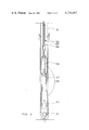
- FIG. 1 shows in diagrammatic form a cross section of the earth with wells penetrating a heavy oil or tar sands reservoir, the wells being equipped for operations in accordance with this invention.
- FIG. 2 is a diagrammatic representation of a hollow sucker rod pump which can be advantageously employed in the producing well associated with this invention.
- Direct wellbore stimulation has in the past been frequently carried out by local application of steam. Such stimulation has thus far proved less than successful.
- the injection of steam to remove the tar and reduce its viscosity into such a production well has also frequently resulted in creation of voids in the unconsolidated sand, resulting in dissipation of the gravel pack which apparently migrates or flows into such voids.
- a producing wellbore can be indirectly thermally stimulated through an adjacent thermal stimulation well located a distance of the order of about 10 to about 50 feet away from the producing well.
- said thermal stimulation well can, for most purposes, be considered expendable. That is, it will not be involved in the direct production process during most of the operating time of such a project. Hence the cost is low.
- FIG. 1 shows a highly schematic diagram of a thermal stimulation well design for the purpose of indirectly thermally stimulating the producing well 11 either by the injection of steam through an adjacent well 12 or by compressed air flow from a well 13, which causes a local combustion front to be formed.
- both of the wells 12 and 13 are not to be employed with a single producing well 11, but rather these are alternative designs. Either can be successfully employed.
- the general scheme of operation and in fact the general arrangement of apparatus is mostly common between these two designs.
- the adjacent well 12 or 13 may be equipped with a heat resistant alloy in the part extending through the reservoir (the producing zone) or (and this will usually be the case) it may be equipped with carbon steel casing throughout.
- the casing may be run to total depth and cemented in the conventional manner, provided the casing is designed to have sufficient strength to withstand the thermal stresses imposed by the difference in temperature in the well.
- the casing string may be prestressed, as is well known in this art, to provide sufficient tension so that subsequent compressive stresses caused by thermal elongation between top and bottom of the well are insufficient to cause the casing to be in compression.
- a number of such wells of the design shown in FIG. 1 with prestressed carbon steel casing have been used successfully in steam stimulation of wells in the Athabasca tar sand from an adjacent well spaced approximately 10 to 50 feet, at a total depth of approximately 1100 feet.
- the arrangement at the producing well 11 may be as shown in FIG. 1.
- the main string of casing 15 has been cemented at the top of the reservoir sand 16. Since the lower part of this cement will be exposed to relatively high temperatures, we used a high temperature cement mix to cement the casing to the surface.
- the underreamed hole is filled with a gravel pack 19.
- the length of the liner is such that additional gravel can be packed into the annular space between the casing 15 and the upper end of the liner 17, ending a few feet below the top of this liner. Then this last space is sealed off, preferably by pouring in a small amount of high temperature resistant cement slurry or alternatively by setting a packer at this point (20).
- the well is then ready for running in of the pump 21.
- the pump and its hollow sucker rod 22 are shown in more detail in FIG. 2.
- thermocouple string (23) which may, for example, be a 1 inch tubing string in the annulus extended to near the bottom of the well.
- the steam stimulator of adjacent well 12 similarly has casing 26 (note above discussion about use of carbon steel casing) which is cemented to a depth approaching that of the production well 11 using high temperature resistant cement.
- Perforations 27 on a lower level and 28 on an upper level in the heavy oil or tar sand reservoir 16 are made through the casing 26. These can, for example, be produced by use of an abrasive jet perforated technique.
- the lower perforations are to be used for injection of the steam, the upper for the injection of a divertant such as water or a dilute aqueous soap solution, as described below.
- the steam injection tubing 30 (which may, for example, be 3 inch tubing) is run to a depth approaching that of the lower perforations 27.
- a thermal packer 19 Near the bottom of the string is a thermal packer 19, and a distance of approximately 10 to 30 feet above this is located an expansion joint 31.
- This expansion joint takes care of axial motion which otherwise might cause buckling due to thermal elongation of the tubing string 30.
- a small thermocouple string 32 for example a string of one inch tubing, is run in above the packer.
- the packer divides this adjacent well 12 into two passage ways, a lower part connected to the surface through the tubing 30 and an upper part communicating with the upper part of the formation through the upper perforations and the annular space in the well 12.
- the heated zone spreads out about radially along the lower part of the reservoir 16 until it finally encircles the lower part of the producing well 11. As soon as this has been accomplished, it is assumed that the reservoir around the injection well has been sufficiently heated so that a successful frontal thermal drive can be carried out.
- the arrangement in the well 13 is another way of causing indirect stimulation through a twin well.
- the stimulation is to be by local combustion drive.
- the casing 35 is cemented essentially as in well 12.
- Injection perforations 36 were made with a liquid jet perforating technique in the lower part of the well; an upper set 37 were similarly provided.
- a 3 inch tubing string 38 was run, carrying at its lower end a burner assembly such as shown in Hujsak U.S. Pat. No. 3,223,165 and above it a thermal packer 40.
- the packer 40 was set in the conventional manner.
- the usual thermocouple string 41 was run (1 inch tubing) with the thermocouple located near the upper perforations 37.
- a one inch gas injection tubing 42 was run inside of tubing 38 to mix the gas and air in the burner assembly and ignite the formation.
- Operations of this sort were carried out for a period of the order of 10 to 90 days when the separation D is of the order of 10 to 50 feet, followed by a 1 to 4 day shut-in period to insure that the formation heating zone encircles the producing well 11, permitting it to produce the locally heated thick oil or melted tar and raise the flow capacity of this region, to minimize bypassing of combustion gas or hot tar or the like.
- the estimated heat energy in the combustion ranged from 1.8 to 4.1 billion BTU; this required injection of around 50 MMCF of air.
- a distinct limitation was keeping the production well temperature to not over 500° F. This can be accomplished by injecting cooling water into the producing well.
- Both the wells 12 and 13 shown for the indirect stimulation accomplish essentially the same ultimate purpose: the lower part of the zone near the producing well is raised in flow capacity while high temperatures are kept away from the upper zone of the formation and the adjacent parts of the well.
- FIG. 2 A preferred arrangement of handling the pumping in the producing well is shown in FIG. 2.
- the tubing 21 carries the pump barrel 50, at the lower end of which is located a retrievable standing valve 51.
- the traveling valve 52 equipped with puller is mounted at the bottom of the plunger 53 which in this case is shown with two piston sections and an intermediate section of smaller diameter.
- a crossover tube 54 of relatively small diameter leads from this narrow zone to the connection to the sucker rods, where it connects fluid tight to the hollow sucker rods 55.
- an injection check valve 56 Preferably mounted in the hollow sucker rods just above the pump is an injection check valve 56 preventing fluid flow up through the sucker rod tubing.
- a check valve and perforation assembly 57 permitting fluid flow down the hollow sucker rod 55, through the crossover tube 54, and out through unit 57 past its check valve, which enables fluid to be pumped into the annular space by the pump. This permits the dilution of the thick oil or tar to a lower viscosity, which can be pumped out at the wellbore. It can also be utilized as a cooling water injection string to reduce operating temperatures in the wellbore.
- Heating at one level in the formation can occur while production occurs at the same or at a different level in the producing well.
Abstract
Description
Claims (5)
Priority Applications (2)
| Application Number | Priority Date | Filing Date | Title |
|---|---|---|---|
| US06/002,495 US4274487A (en) | 1979-01-11 | 1979-01-11 | Indirect thermal stimulation of production wells |
| CA000335681A CA1118341A (en) | 1979-01-11 | 1979-09-14 | Indirect thermal stimulation of producing wells |
Applications Claiming Priority (1)
| Application Number | Priority Date | Filing Date | Title |
|---|---|---|---|
| US06/002,495 US4274487A (en) | 1979-01-11 | 1979-01-11 | Indirect thermal stimulation of production wells |
Publications (1)
| Publication Number | Publication Date |
|---|---|
| US4274487A true US4274487A (en) | 1981-06-23 |
Family
ID=21701053
Family Applications (1)
| Application Number | Title | Priority Date | Filing Date |
|---|---|---|---|
| US06/002,495 Expired - Lifetime US4274487A (en) | 1979-01-11 | 1979-01-11 | Indirect thermal stimulation of production wells |
Country Status (2)
| Country | Link |
|---|---|
| US (1) | US4274487A (en) |
| CA (1) | CA1118341A (en) |
Cited By (46)
| Publication number | Priority date | Publication date | Assignee | Title |
|---|---|---|---|---|
| US4392530A (en) * | 1981-04-30 | 1983-07-12 | Mobil Oil Corporation | Method of improved oil recovery by simultaneous injection of steam and water |
| US4431055A (en) * | 1980-02-06 | 1984-02-14 | Standard Oil Company (Indiana) | Method for selective plugging of depleted channels or zones in in situ oil shale retorts |
| US4493369A (en) * | 1981-04-30 | 1985-01-15 | Mobil Oil Corporation | Method of improved oil recovery by simultaneous injection of water with an in-situ combustion process |
| US4509595A (en) * | 1981-01-28 | 1985-04-09 | Canadian Liquid Air Ltd/Air Liquide | In situ combustion for oil recovery |
| US4640355A (en) * | 1985-03-26 | 1987-02-03 | Chevron Research Company | Limited entry method for multiple zone, compressible fluid injection |
| US4759408A (en) * | 1987-06-08 | 1988-07-26 | Texaco Inc. | Method of shutting off a portion of a producing zone in a hydrocarbon producing well |
| US4834178A (en) * | 1987-03-18 | 1989-05-30 | Union Carbide Corporation | Process for injection of oxidant and liquid into a well |
| US6481503B2 (en) * | 2001-01-08 | 2002-11-19 | Baker Hughes Incorporated | Multi-purpose injection and production well system |
| US6581684B2 (en) | 2000-04-24 | 2003-06-24 | Shell Oil Company | In Situ thermal processing of a hydrocarbon containing formation to produce sulfur containing formation fluids |
| US6588504B2 (en) | 2000-04-24 | 2003-07-08 | Shell Oil Company | In situ thermal processing of a coal formation to produce nitrogen and/or sulfur containing formation fluids |
| US6698515B2 (en) | 2000-04-24 | 2004-03-02 | Shell Oil Company | In situ thermal processing of a coal formation using a relatively slow heating rate |
| US6715548B2 (en) | 2000-04-24 | 2004-04-06 | Shell Oil Company | In situ thermal processing of a hydrocarbon containing formation to produce nitrogen containing formation fluids |
| US6715546B2 (en) | 2000-04-24 | 2004-04-06 | Shell Oil Company | In situ production of synthesis gas from a hydrocarbon containing formation through a heat source wellbore |
| US20060207762A1 (en) * | 2004-06-07 | 2006-09-21 | Conrad Ayasse | Oilfield enhanced in situ combustion process |
| US20080066907A1 (en) * | 2004-06-07 | 2008-03-20 | Archon Technologies Ltd. | Oilfield Enhanced in Situ Combustion Process |
| US7644765B2 (en) | 2006-10-20 | 2010-01-12 | Shell Oil Company | Heating tar sands formations while controlling pressure |
| US7673786B2 (en) | 2006-04-21 | 2010-03-09 | Shell Oil Company | Welding shield for coupling heaters |
| US7735935B2 (en) | 2001-04-24 | 2010-06-15 | Shell Oil Company | In situ thermal processing of an oil shale formation containing carbonate minerals |
| US7770643B2 (en) | 2006-10-10 | 2010-08-10 | Halliburton Energy Services, Inc. | Hydrocarbon recovery using fluids |
| US7798220B2 (en) | 2007-04-20 | 2010-09-21 | Shell Oil Company | In situ heat treatment of a tar sands formation after drive process treatment |
| US7809538B2 (en) | 2006-01-13 | 2010-10-05 | Halliburton Energy Services, Inc. | Real time monitoring and control of thermal recovery operations for heavy oil reservoirs |
| US7831134B2 (en) | 2005-04-22 | 2010-11-09 | Shell Oil Company | Grouped exposed metal heaters |
| US7832482B2 (en) | 2006-10-10 | 2010-11-16 | Halliburton Energy Services, Inc. | Producing resources using steam injection |
| US7866388B2 (en) | 2007-10-19 | 2011-01-11 | Shell Oil Company | High temperature methods for forming oxidizer fuel |
| US20110036575A1 (en) * | 2007-07-06 | 2011-02-17 | Cavender Travis W | Producing resources using heated fluid injection |
| US7942203B2 (en) | 2003-04-24 | 2011-05-17 | Shell Oil Company | Thermal processes for subsurface formations |
| US20120080199A1 (en) * | 2010-09-30 | 2012-04-05 | Conocophillips Company | Double string slurry pump |
| US8151907B2 (en) | 2008-04-18 | 2012-04-10 | Shell Oil Company | Dual motor systems and non-rotating sensors for use in developing wellbores in subsurface formations |
| US8151880B2 (en) | 2005-10-24 | 2012-04-10 | Shell Oil Company | Methods of making transportation fuel |
| US8224163B2 (en) | 2002-10-24 | 2012-07-17 | Shell Oil Company | Variable frequency temperature limited heaters |
| US8220539B2 (en) | 2008-10-13 | 2012-07-17 | Shell Oil Company | Controlling hydrogen pressure in self-regulating nuclear reactors used to treat a subsurface formation |
| US8327932B2 (en) | 2009-04-10 | 2012-12-11 | Shell Oil Company | Recovering energy from a subsurface formation |
| US8355623B2 (en) | 2004-04-23 | 2013-01-15 | Shell Oil Company | Temperature limited heaters with high power factors |
| US8627887B2 (en) | 2001-10-24 | 2014-01-14 | Shell Oil Company | In situ recovery from a hydrocarbon containing formation |
| US8631866B2 (en) | 2010-04-09 | 2014-01-21 | Shell Oil Company | Leak detection in circulated fluid systems for heating subsurface formations |
| US8701769B2 (en) | 2010-04-09 | 2014-04-22 | Shell Oil Company | Methods for treating hydrocarbon formations based on geology |
| US8820406B2 (en) | 2010-04-09 | 2014-09-02 | Shell Oil Company | Electrodes for electrical current flow heating of subsurface formations with conductive material in wellbore |
| AU2010300521B2 (en) * | 2009-09-30 | 2015-04-16 | Conocophillips Company | Double string pump for hydrocarbon wells |
| US9016370B2 (en) | 2011-04-08 | 2015-04-28 | Shell Oil Company | Partial solution mining of hydrocarbon containing layers prior to in situ heat treatment |
| US9033042B2 (en) | 2010-04-09 | 2015-05-19 | Shell Oil Company | Forming bitumen barriers in subsurface hydrocarbon formations |
| US9309755B2 (en) | 2011-10-07 | 2016-04-12 | Shell Oil Company | Thermal expansion accommodation for circulated fluid systems used to heat subsurface formations |
| US10047594B2 (en) | 2012-01-23 | 2018-08-14 | Genie Ip B.V. | Heater pattern for in situ thermal processing of a subsurface hydrocarbon containing formation |
| US10487636B2 (en) | 2017-07-27 | 2019-11-26 | Exxonmobil Upstream Research Company | Enhanced methods for recovering viscous hydrocarbons from a subterranean formation as a follow-up to thermal recovery processes |
| US11002123B2 (en) | 2017-08-31 | 2021-05-11 | Exxonmobil Upstream Research Company | Thermal recovery methods for recovering viscous hydrocarbons from a subterranean formation |
| US11142681B2 (en) | 2017-06-29 | 2021-10-12 | Exxonmobil Upstream Research Company | Chasing solvent for enhanced recovery processes |
| US11261725B2 (en) | 2017-10-24 | 2022-03-01 | Exxonmobil Upstream Research Company | Systems and methods for estimating and controlling liquid level using periodic shut-ins |
Families Citing this family (1)
| Publication number | Priority date | Publication date | Assignee | Title |
|---|---|---|---|---|
| CN103590798B (en) * | 2013-10-15 | 2016-08-31 | 中国石油天然气股份有限公司 | A kind of super-viscous oil steam injection recovery is boiled in a covered pot over a slow fire the determination method of well time and calculates device |
Citations (10)
| Publication number | Priority date | Publication date | Assignee | Title |
|---|---|---|---|---|
| US2906337A (en) * | 1957-08-16 | 1959-09-29 | Pure Oil Co | Method of recovering bitumen |
| US2994375A (en) * | 1957-12-23 | 1961-08-01 | Phillips Petroleum Co | Recovery of hydrocarbons by in situ combustion |
| US2994377A (en) * | 1958-03-24 | 1961-08-01 | Phillips Petroleum Co | In situ combustion in carbonaceous strata |
| US3062282A (en) * | 1958-01-24 | 1962-11-06 | Phillips Petroleum Co | Initiation of in situ combustion in a carbonaceous stratum |
| US3097690A (en) * | 1958-12-24 | 1963-07-16 | Gulf Research Development Co | Process for heating a subsurface formation |
| US3272261A (en) * | 1963-12-13 | 1966-09-13 | Gulf Research Development Co | Process for recovery of oil |
| US3964547A (en) * | 1973-01-15 | 1976-06-22 | Amoco Production Company | Recovery of heavy hydrocarbons from underground formations |
| US3978920A (en) * | 1975-10-24 | 1976-09-07 | Cities Service Company | In situ combustion process for multi-stratum reservoirs |
| US4068715A (en) * | 1975-10-08 | 1978-01-17 | Texaco Inc. | Method for recovering viscous petroleum |
| US4088188A (en) * | 1975-12-24 | 1978-05-09 | Texaco Inc. | High vertical conformance steam injection petroleum recovery method |
-
1979
- 1979-01-11 US US06/002,495 patent/US4274487A/en not_active Expired - Lifetime
- 1979-09-14 CA CA000335681A patent/CA1118341A/en not_active Expired
Patent Citations (10)
| Publication number | Priority date | Publication date | Assignee | Title |
|---|---|---|---|---|
| US2906337A (en) * | 1957-08-16 | 1959-09-29 | Pure Oil Co | Method of recovering bitumen |
| US2994375A (en) * | 1957-12-23 | 1961-08-01 | Phillips Petroleum Co | Recovery of hydrocarbons by in situ combustion |
| US3062282A (en) * | 1958-01-24 | 1962-11-06 | Phillips Petroleum Co | Initiation of in situ combustion in a carbonaceous stratum |
| US2994377A (en) * | 1958-03-24 | 1961-08-01 | Phillips Petroleum Co | In situ combustion in carbonaceous strata |
| US3097690A (en) * | 1958-12-24 | 1963-07-16 | Gulf Research Development Co | Process for heating a subsurface formation |
| US3272261A (en) * | 1963-12-13 | 1966-09-13 | Gulf Research Development Co | Process for recovery of oil |
| US3964547A (en) * | 1973-01-15 | 1976-06-22 | Amoco Production Company | Recovery of heavy hydrocarbons from underground formations |
| US4068715A (en) * | 1975-10-08 | 1978-01-17 | Texaco Inc. | Method for recovering viscous petroleum |
| US3978920A (en) * | 1975-10-24 | 1976-09-07 | Cities Service Company | In situ combustion process for multi-stratum reservoirs |
| US4088188A (en) * | 1975-12-24 | 1978-05-09 | Texaco Inc. | High vertical conformance steam injection petroleum recovery method |
Cited By (189)
| Publication number | Priority date | Publication date | Assignee | Title |
|---|---|---|---|---|
| US4431055A (en) * | 1980-02-06 | 1984-02-14 | Standard Oil Company (Indiana) | Method for selective plugging of depleted channels or zones in in situ oil shale retorts |
| US4509595A (en) * | 1981-01-28 | 1985-04-09 | Canadian Liquid Air Ltd/Air Liquide | In situ combustion for oil recovery |
| US4392530A (en) * | 1981-04-30 | 1983-07-12 | Mobil Oil Corporation | Method of improved oil recovery by simultaneous injection of steam and water |
| US4493369A (en) * | 1981-04-30 | 1985-01-15 | Mobil Oil Corporation | Method of improved oil recovery by simultaneous injection of water with an in-situ combustion process |
| US4640355A (en) * | 1985-03-26 | 1987-02-03 | Chevron Research Company | Limited entry method for multiple zone, compressible fluid injection |
| US4834178A (en) * | 1987-03-18 | 1989-05-30 | Union Carbide Corporation | Process for injection of oxidant and liquid into a well |
| US4759408A (en) * | 1987-06-08 | 1988-07-26 | Texaco Inc. | Method of shutting off a portion of a producing zone in a hydrocarbon producing well |
| US6820688B2 (en) | 2000-04-24 | 2004-11-23 | Shell Oil Company | In situ thermal processing of coal formation with a selected hydrogen content and/or selected H/C ratio |
| US8225866B2 (en) | 2000-04-24 | 2012-07-24 | Shell Oil Company | In situ recovery from a hydrocarbon containing formation |
| US6588504B2 (en) | 2000-04-24 | 2003-07-08 | Shell Oil Company | In situ thermal processing of a coal formation to produce nitrogen and/or sulfur containing formation fluids |
| US6591906B2 (en) | 2000-04-24 | 2003-07-15 | Shell Oil Company | In situ thermal processing of a hydrocarbon containing formation with a selected oxygen content |
| US6591907B2 (en) | 2000-04-24 | 2003-07-15 | Shell Oil Company | In situ thermal processing of a coal formation with a selected vitrinite reflectance |
| US6607033B2 (en) | 2000-04-24 | 2003-08-19 | Shell Oil Company | In Situ thermal processing of a coal formation to produce a condensate |
| US6609570B2 (en) | 2000-04-24 | 2003-08-26 | Shell Oil Company | In situ thermal processing of a coal formation and ammonia production |
| US6688387B1 (en) | 2000-04-24 | 2004-02-10 | Shell Oil Company | In situ thermal processing of a hydrocarbon containing formation to produce a hydrocarbon condensate |
| US6698515B2 (en) | 2000-04-24 | 2004-03-02 | Shell Oil Company | In situ thermal processing of a coal formation using a relatively slow heating rate |
| US6702016B2 (en) | 2000-04-24 | 2004-03-09 | Shell Oil Company | In situ thermal processing of a hydrocarbon containing formation with heat sources located at an edge of a formation layer |
| US6708758B2 (en) | 2000-04-24 | 2004-03-23 | Shell Oil Company | In situ thermal processing of a coal formation leaving one or more selected unprocessed areas |
| US6712135B2 (en) | 2000-04-24 | 2004-03-30 | Shell Oil Company | In situ thermal processing of a coal formation in reducing environment |
| US6712136B2 (en) | 2000-04-24 | 2004-03-30 | Shell Oil Company | In situ thermal processing of a hydrocarbon containing formation using a selected production well spacing |
| US6712137B2 (en) | 2000-04-24 | 2004-03-30 | Shell Oil Company | In situ thermal processing of a coal formation to pyrolyze a selected percentage of hydrocarbon material |
| US6715548B2 (en) | 2000-04-24 | 2004-04-06 | Shell Oil Company | In situ thermal processing of a hydrocarbon containing formation to produce nitrogen containing formation fluids |
| US6715546B2 (en) | 2000-04-24 | 2004-04-06 | Shell Oil Company | In situ production of synthesis gas from a hydrocarbon containing formation through a heat source wellbore |
| US6715549B2 (en) | 2000-04-24 | 2004-04-06 | Shell Oil Company | In situ thermal processing of a hydrocarbon containing formation with a selected atomic oxygen to carbon ratio |
| US6715547B2 (en) | 2000-04-24 | 2004-04-06 | Shell Oil Company | In situ thermal processing of a hydrocarbon containing formation to form a substantially uniform, high permeability formation |
| US6719047B2 (en) | 2000-04-24 | 2004-04-13 | Shell Oil Company | In situ thermal processing of a hydrocarbon containing formation in a hydrogen-rich environment |
| US6722431B2 (en) | 2000-04-24 | 2004-04-20 | Shell Oil Company | In situ thermal processing of hydrocarbons within a relatively permeable formation |
| US6722429B2 (en) | 2000-04-24 | 2004-04-20 | Shell Oil Company | In situ thermal processing of a hydrocarbon containing formation leaving one or more selected unprocessed areas |
| US6722430B2 (en) | 2000-04-24 | 2004-04-20 | Shell Oil Company | In situ thermal processing of a coal formation with a selected oxygen content and/or selected O/C ratio |
| US6725920B2 (en) | 2000-04-24 | 2004-04-27 | Shell Oil Company | In situ thermal processing of a hydrocarbon containing formation to convert a selected amount of total organic carbon into hydrocarbon products |
| US6725928B2 (en) | 2000-04-24 | 2004-04-27 | Shell Oil Company | In situ thermal processing of a coal formation using a distributed combustor |
| US6725921B2 (en) | 2000-04-24 | 2004-04-27 | Shell Oil Company | In situ thermal processing of a coal formation by controlling a pressure of the formation |
| US6729397B2 (en) | 2000-04-24 | 2004-05-04 | Shell Oil Company | In situ thermal processing of a hydrocarbon containing formation with a selected vitrinite reflectance |
| US6729396B2 (en) | 2000-04-24 | 2004-05-04 | Shell Oil Company | In situ thermal processing of a coal formation to produce hydrocarbons having a selected carbon number range |
| US6729401B2 (en) | 2000-04-24 | 2004-05-04 | Shell Oil Company | In situ thermal processing of a hydrocarbon containing formation and ammonia production |
| US6729395B2 (en) | 2000-04-24 | 2004-05-04 | Shell Oil Company | In situ thermal processing of a hydrocarbon containing formation with a selected ratio of heat sources to production wells |
| US6732794B2 (en) | 2000-04-24 | 2004-05-11 | Shell Oil Company | In situ thermal processing of a hydrocarbon containing formation to produce a mixture with a selected hydrogen content |
| US6732795B2 (en) | 2000-04-24 | 2004-05-11 | Shell Oil Company | In situ thermal processing of a hydrocarbon containing formation to pyrolyze a selected percentage of hydrocarbon material |
| US6732796B2 (en) | 2000-04-24 | 2004-05-11 | Shell Oil Company | In situ production of synthesis gas from a hydrocarbon containing formation, the synthesis gas having a selected H2 to CO ratio |
| US6736215B2 (en) | 2000-04-24 | 2004-05-18 | Shell Oil Company | In situ thermal processing of a hydrocarbon containing formation, in situ production of synthesis gas, and carbon dioxide sequestration |
| US6739393B2 (en) | 2000-04-24 | 2004-05-25 | Shell Oil Company | In situ thermal processing of a coal formation and tuning production |
| US6739394B2 (en) | 2000-04-24 | 2004-05-25 | Shell Oil Company | Production of synthesis gas from a hydrocarbon containing formation |
| US6742593B2 (en) | 2000-04-24 | 2004-06-01 | Shell Oil Company | In situ thermal processing of a hydrocarbon containing formation using heat transfer from a heat transfer fluid to heat the formation |
| US6742588B2 (en) | 2000-04-24 | 2004-06-01 | Shell Oil Company | In situ thermal processing of a hydrocarbon containing formation to produce formation fluids having a relatively low olefin content |
| US6742589B2 (en) | 2000-04-24 | 2004-06-01 | Shell Oil Company | In situ thermal processing of a coal formation using repeating triangular patterns of heat sources |
| US6742587B2 (en) | 2000-04-24 | 2004-06-01 | Shell Oil Company | In situ thermal processing of a coal formation to form a substantially uniform, relatively high permeable formation |
| US6745832B2 (en) | 2000-04-24 | 2004-06-08 | Shell Oil Company | Situ thermal processing of a hydrocarbon containing formation to control product composition |
| US6745831B2 (en) | 2000-04-24 | 2004-06-08 | Shell Oil Company | In situ thermal processing of a hydrocarbon containing formation by controlling a pressure of the formation |
| US6745837B2 (en) | 2000-04-24 | 2004-06-08 | Shell Oil Company | In situ thermal processing of a hydrocarbon containing formation using a controlled heating rate |
| US6749021B2 (en) | 2000-04-24 | 2004-06-15 | Shell Oil Company | In situ thermal processing of a coal formation using a controlled heating rate |
| US8485252B2 (en) | 2000-04-24 | 2013-07-16 | Shell Oil Company | In situ recovery from a hydrocarbon containing formation |
| US6758268B2 (en) | 2000-04-24 | 2004-07-06 | Shell Oil Company | In situ thermal processing of a hydrocarbon containing formation using a relatively slow heating rate |
| US6761216B2 (en) | 2000-04-24 | 2004-07-13 | Shell Oil Company | In situ thermal processing of a coal formation to produce hydrocarbon fluids and synthesis gas |
| US6763886B2 (en) | 2000-04-24 | 2004-07-20 | Shell Oil Company | In situ thermal processing of a coal formation with carbon dioxide sequestration |
| US6769483B2 (en) | 2000-04-24 | 2004-08-03 | Shell Oil Company | In situ thermal processing of a hydrocarbon containing formation using conductor in conduit heat sources |
| US6769485B2 (en) | 2000-04-24 | 2004-08-03 | Shell Oil Company | In situ production of synthesis gas from a coal formation through a heat source wellbore |
| US6789625B2 (en) | 2000-04-24 | 2004-09-14 | Shell Oil Company | In situ thermal processing of a hydrocarbon containing formation using exposed metal heat sources |
| US6805195B2 (en) | 2000-04-24 | 2004-10-19 | Shell Oil Company | In situ thermal processing of a hydrocarbon containing formation to produce hydrocarbon fluids and synthesis gas |
| US8789586B2 (en) | 2000-04-24 | 2014-07-29 | Shell Oil Company | In situ recovery from a hydrocarbon containing formation |
| US7798221B2 (en) | 2000-04-24 | 2010-09-21 | Shell Oil Company | In situ recovery from a hydrocarbon containing formation |
| US6581684B2 (en) | 2000-04-24 | 2003-06-24 | Shell Oil Company | In Situ thermal processing of a hydrocarbon containing formation to produce sulfur containing formation fluids |
| US6752210B2 (en) | 2000-04-24 | 2004-06-22 | Shell Oil Company | In situ thermal processing of a coal formation using heat sources positioned within open wellbores |
| USRE40308E1 (en) | 2001-01-08 | 2008-05-13 | Baker Hughes Incorporated | Multi-purpose injection and production well system |
| US6481503B2 (en) * | 2001-01-08 | 2002-11-19 | Baker Hughes Incorporated | Multi-purpose injection and production well system |
| US8608249B2 (en) | 2001-04-24 | 2013-12-17 | Shell Oil Company | In situ thermal processing of an oil shale formation |
| US7735935B2 (en) | 2001-04-24 | 2010-06-15 | Shell Oil Company | In situ thermal processing of an oil shale formation containing carbonate minerals |
| US8627887B2 (en) | 2001-10-24 | 2014-01-14 | Shell Oil Company | In situ recovery from a hydrocarbon containing formation |
| US8224164B2 (en) | 2002-10-24 | 2012-07-17 | Shell Oil Company | Insulated conductor temperature limited heaters |
| US8238730B2 (en) | 2002-10-24 | 2012-08-07 | Shell Oil Company | High voltage temperature limited heaters |
| US20130043029A1 (en) * | 2002-10-24 | 2013-02-21 | Shell Oil Company | High voltage temperature limited heaters |
| US8224163B2 (en) | 2002-10-24 | 2012-07-17 | Shell Oil Company | Variable frequency temperature limited heaters |
| US8579031B2 (en) | 2003-04-24 | 2013-11-12 | Shell Oil Company | Thermal processes for subsurface formations |
| US7942203B2 (en) | 2003-04-24 | 2011-05-17 | Shell Oil Company | Thermal processes for subsurface formations |
| US8355623B2 (en) | 2004-04-23 | 2013-01-15 | Shell Oil Company | Temperature limited heaters with high power factors |
| US20080169096A1 (en) * | 2004-06-07 | 2008-07-17 | Conrad Ayasse | Oilfield enhanced in situ combustion process |
| US20080066907A1 (en) * | 2004-06-07 | 2008-03-20 | Archon Technologies Ltd. | Oilfield Enhanced in Situ Combustion Process |
| US20060207762A1 (en) * | 2004-06-07 | 2006-09-21 | Conrad Ayasse | Oilfield enhanced in situ combustion process |
| US7493953B2 (en) * | 2004-06-07 | 2009-02-24 | Archon Technologies Lcd. | Oilfield enhanced in situ combustion process |
| US7493952B2 (en) * | 2004-06-07 | 2009-02-24 | Archon Technologies Ltd. | Oilfield enhanced in situ combustion process |
| US8233782B2 (en) | 2005-04-22 | 2012-07-31 | Shell Oil Company | Grouped exposed metal heaters |
| US7942197B2 (en) | 2005-04-22 | 2011-05-17 | Shell Oil Company | Methods and systems for producing fluid from an in situ conversion process |
| US7986869B2 (en) | 2005-04-22 | 2011-07-26 | Shell Oil Company | Varying properties along lengths of temperature limited heaters |
| US8027571B2 (en) | 2005-04-22 | 2011-09-27 | Shell Oil Company | In situ conversion process systems utilizing wellbores in at least two regions of a formation |
| US8070840B2 (en) | 2005-04-22 | 2011-12-06 | Shell Oil Company | Treatment of gas from an in situ conversion process |
| US7831134B2 (en) | 2005-04-22 | 2010-11-09 | Shell Oil Company | Grouped exposed metal heaters |
| US8230927B2 (en) | 2005-04-22 | 2012-07-31 | Shell Oil Company | Methods and systems for producing fluid from an in situ conversion process |
| US7860377B2 (en) | 2005-04-22 | 2010-12-28 | Shell Oil Company | Subsurface connection methods for subsurface heaters |
| US8224165B2 (en) | 2005-04-22 | 2012-07-17 | Shell Oil Company | Temperature limited heater utilizing non-ferromagnetic conductor |
| US8151880B2 (en) | 2005-10-24 | 2012-04-10 | Shell Oil Company | Methods of making transportation fuel |
| US8606091B2 (en) | 2005-10-24 | 2013-12-10 | Shell Oil Company | Subsurface heaters with low sulfidation rates |
| US7809538B2 (en) | 2006-01-13 | 2010-10-05 | Halliburton Energy Services, Inc. | Real time monitoring and control of thermal recovery operations for heavy oil reservoirs |
| US8192682B2 (en) | 2006-04-21 | 2012-06-05 | Shell Oil Company | High strength alloys |
| US7683296B2 (en) | 2006-04-21 | 2010-03-23 | Shell Oil Company | Adjusting alloy compositions for selected properties in temperature limited heaters |
| US7866385B2 (en) | 2006-04-21 | 2011-01-11 | Shell Oil Company | Power systems utilizing the heat of produced formation fluid |
| US7793722B2 (en) | 2006-04-21 | 2010-09-14 | Shell Oil Company | Non-ferromagnetic overburden casing |
| US8857506B2 (en) | 2006-04-21 | 2014-10-14 | Shell Oil Company | Alternate energy source usage methods for in situ heat treatment processes |
| US7912358B2 (en) | 2006-04-21 | 2011-03-22 | Shell Oil Company | Alternate energy source usage for in situ heat treatment processes |
| US7785427B2 (en) | 2006-04-21 | 2010-08-31 | Shell Oil Company | High strength alloys |
| US7673786B2 (en) | 2006-04-21 | 2010-03-09 | Shell Oil Company | Welding shield for coupling heaters |
| US8083813B2 (en) | 2006-04-21 | 2011-12-27 | Shell Oil Company | Methods of producing transportation fuel |
| US7832482B2 (en) | 2006-10-10 | 2010-11-16 | Halliburton Energy Services, Inc. | Producing resources using steam injection |
| US7770643B2 (en) | 2006-10-10 | 2010-08-10 | Halliburton Energy Services, Inc. | Hydrocarbon recovery using fluids |
| US8555971B2 (en) | 2006-10-20 | 2013-10-15 | Shell Oil Company | Treating tar sands formations with dolomite |
| US7677314B2 (en) | 2006-10-20 | 2010-03-16 | Shell Oil Company | Method of condensing vaporized water in situ to treat tar sands formations |
| US7703513B2 (en) | 2006-10-20 | 2010-04-27 | Shell Oil Company | Wax barrier for use with in situ processes for treating formations |
| US7730947B2 (en) | 2006-10-20 | 2010-06-08 | Shell Oil Company | Creating fluid injectivity in tar sands formations |
| US7681647B2 (en) | 2006-10-20 | 2010-03-23 | Shell Oil Company | Method of producing drive fluid in situ in tar sands formations |
| US7730945B2 (en) | 2006-10-20 | 2010-06-08 | Shell Oil Company | Using geothermal energy to heat a portion of a formation for an in situ heat treatment process |
| US7677310B2 (en) | 2006-10-20 | 2010-03-16 | Shell Oil Company | Creating and maintaining a gas cap in tar sands formations |
| US7717171B2 (en) | 2006-10-20 | 2010-05-18 | Shell Oil Company | Moving hydrocarbons through portions of tar sands formations with a fluid |
| US7730946B2 (en) | 2006-10-20 | 2010-06-08 | Shell Oil Company | Treating tar sands formations with dolomite |
| US7673681B2 (en) | 2006-10-20 | 2010-03-09 | Shell Oil Company | Treating tar sands formations with karsted zones |
| US7644765B2 (en) | 2006-10-20 | 2010-01-12 | Shell Oil Company | Heating tar sands formations while controlling pressure |
| US7841401B2 (en) | 2006-10-20 | 2010-11-30 | Shell Oil Company | Gas injection to inhibit migration during an in situ heat treatment process |
| US7845411B2 (en) | 2006-10-20 | 2010-12-07 | Shell Oil Company | In situ heat treatment process utilizing a closed loop heating system |
| US8191630B2 (en) | 2006-10-20 | 2012-06-05 | Shell Oil Company | Creating fluid injectivity in tar sands formations |
| US8381815B2 (en) | 2007-04-20 | 2013-02-26 | Shell Oil Company | Production from multiple zones of a tar sands formation |
| US8662175B2 (en) | 2007-04-20 | 2014-03-04 | Shell Oil Company | Varying properties of in situ heat treatment of a tar sands formation based on assessed viscosities |
| US9181780B2 (en) | 2007-04-20 | 2015-11-10 | Shell Oil Company | Controlling and assessing pressure conditions during treatment of tar sands formations |
| US7950453B2 (en) | 2007-04-20 | 2011-05-31 | Shell Oil Company | Downhole burner systems and methods for heating subsurface formations |
| US7798220B2 (en) | 2007-04-20 | 2010-09-21 | Shell Oil Company | In situ heat treatment of a tar sands formation after drive process treatment |
| US7832484B2 (en) | 2007-04-20 | 2010-11-16 | Shell Oil Company | Molten salt as a heat transfer fluid for heating a subsurface formation |
| US8791396B2 (en) | 2007-04-20 | 2014-07-29 | Shell Oil Company | Floating insulated conductors for heating subsurface formations |
| US8327681B2 (en) | 2007-04-20 | 2012-12-11 | Shell Oil Company | Wellbore manufacturing processes for in situ heat treatment processes |
| US7841408B2 (en) | 2007-04-20 | 2010-11-30 | Shell Oil Company | In situ heat treatment from multiple layers of a tar sands formation |
| US7841425B2 (en) | 2007-04-20 | 2010-11-30 | Shell Oil Company | Drilling subsurface wellbores with cutting structures |
| US7849922B2 (en) | 2007-04-20 | 2010-12-14 | Shell Oil Company | In situ recovery from residually heated sections in a hydrocarbon containing formation |
| US7931086B2 (en) | 2007-04-20 | 2011-04-26 | Shell Oil Company | Heating systems for heating subsurface formations |
| US8042610B2 (en) | 2007-04-20 | 2011-10-25 | Shell Oil Company | Parallel heater system for subsurface formations |
| US8459359B2 (en) | 2007-04-20 | 2013-06-11 | Shell Oil Company | Treating nahcolite containing formations and saline zones |
| US20110036575A1 (en) * | 2007-07-06 | 2011-02-17 | Cavender Travis W | Producing resources using heated fluid injection |
| US9133697B2 (en) | 2007-07-06 | 2015-09-15 | Halliburton Energy Services, Inc. | Producing resources using heated fluid injection |
| US8276661B2 (en) | 2007-10-19 | 2012-10-02 | Shell Oil Company | Heating subsurface formations by oxidizing fuel on a fuel carrier |
| US8240774B2 (en) | 2007-10-19 | 2012-08-14 | Shell Oil Company | Solution mining and in situ treatment of nahcolite beds |
| US8272455B2 (en) | 2007-10-19 | 2012-09-25 | Shell Oil Company | Methods for forming wellbores in heated formations |
| US8146661B2 (en) | 2007-10-19 | 2012-04-03 | Shell Oil Company | Cryogenic treatment of gas |
| US7866388B2 (en) | 2007-10-19 | 2011-01-11 | Shell Oil Company | High temperature methods for forming oxidizer fuel |
| US7866386B2 (en) | 2007-10-19 | 2011-01-11 | Shell Oil Company | In situ oxidation of subsurface formations |
| US8536497B2 (en) | 2007-10-19 | 2013-09-17 | Shell Oil Company | Methods for forming long subsurface heaters |
| US8011451B2 (en) | 2007-10-19 | 2011-09-06 | Shell Oil Company | Ranging methods for developing wellbores in subsurface formations |
| US8196658B2 (en) | 2007-10-19 | 2012-06-12 | Shell Oil Company | Irregular spacing of heat sources for treating hydrocarbon containing formations |
| US8162059B2 (en) | 2007-10-19 | 2012-04-24 | Shell Oil Company | Induction heaters used to heat subsurface formations |
| US8113272B2 (en) | 2007-10-19 | 2012-02-14 | Shell Oil Company | Three-phase heaters with common overburden sections for heating subsurface formations |
| US8146669B2 (en) | 2007-10-19 | 2012-04-03 | Shell Oil Company | Multi-step heater deployment in a subsurface formation |
| US8636323B2 (en) | 2008-04-18 | 2014-01-28 | Shell Oil Company | Mines and tunnels for use in treating subsurface hydrocarbon containing formations |
| US8151907B2 (en) | 2008-04-18 | 2012-04-10 | Shell Oil Company | Dual motor systems and non-rotating sensors for use in developing wellbores in subsurface formations |
| US8752904B2 (en) | 2008-04-18 | 2014-06-17 | Shell Oil Company | Heated fluid flow in mines and tunnels used in heating subsurface hydrocarbon containing formations |
| US8162405B2 (en) | 2008-04-18 | 2012-04-24 | Shell Oil Company | Using tunnels for treating subsurface hydrocarbon containing formations |
| US8172335B2 (en) | 2008-04-18 | 2012-05-08 | Shell Oil Company | Electrical current flow between tunnels for use in heating subsurface hydrocarbon containing formations |
| US8562078B2 (en) | 2008-04-18 | 2013-10-22 | Shell Oil Company | Hydrocarbon production from mines and tunnels used in treating subsurface hydrocarbon containing formations |
| US9528322B2 (en) | 2008-04-18 | 2016-12-27 | Shell Oil Company | Dual motor systems and non-rotating sensors for use in developing wellbores in subsurface formations |
| US8177305B2 (en) | 2008-04-18 | 2012-05-15 | Shell Oil Company | Heater connections in mines and tunnels for use in treating subsurface hydrocarbon containing formations |
| US8220539B2 (en) | 2008-10-13 | 2012-07-17 | Shell Oil Company | Controlling hydrogen pressure in self-regulating nuclear reactors used to treat a subsurface formation |
| US8267170B2 (en) | 2008-10-13 | 2012-09-18 | Shell Oil Company | Offset barrier wells in subsurface formations |
| US8281861B2 (en) | 2008-10-13 | 2012-10-09 | Shell Oil Company | Circulated heated transfer fluid heating of subsurface hydrocarbon formations |
| US9129728B2 (en) | 2008-10-13 | 2015-09-08 | Shell Oil Company | Systems and methods of forming subsurface wellbores |
| US9051829B2 (en) | 2008-10-13 | 2015-06-09 | Shell Oil Company | Perforated electrical conductors for treating subsurface formations |
| US9022118B2 (en) | 2008-10-13 | 2015-05-05 | Shell Oil Company | Double insulated heaters for treating subsurface formations |
| US8881806B2 (en) | 2008-10-13 | 2014-11-11 | Shell Oil Company | Systems and methods for treating a subsurface formation with electrical conductors |
| US8353347B2 (en) | 2008-10-13 | 2013-01-15 | Shell Oil Company | Deployment of insulated conductors for treating subsurface formations |
| US8256512B2 (en) | 2008-10-13 | 2012-09-04 | Shell Oil Company | Movable heaters for treating subsurface hydrocarbon containing formations |
| US8261832B2 (en) | 2008-10-13 | 2012-09-11 | Shell Oil Company | Heating subsurface formations with fluids |
| US8267185B2 (en) | 2008-10-13 | 2012-09-18 | Shell Oil Company | Circulated heated transfer fluid systems used to treat a subsurface formation |
| US8327932B2 (en) | 2009-04-10 | 2012-12-11 | Shell Oil Company | Recovering energy from a subsurface formation |
| US8448707B2 (en) | 2009-04-10 | 2013-05-28 | Shell Oil Company | Non-conducting heater casings |
| US8851170B2 (en) | 2009-04-10 | 2014-10-07 | Shell Oil Company | Heater assisted fluid treatment of a subsurface formation |
| US8434555B2 (en) | 2009-04-10 | 2013-05-07 | Shell Oil Company | Irregular pattern treatment of a subsurface formation |
| AU2010300521B2 (en) * | 2009-09-30 | 2015-04-16 | Conocophillips Company | Double string pump for hydrocarbon wells |
| US8739874B2 (en) | 2010-04-09 | 2014-06-03 | Shell Oil Company | Methods for heating with slots in hydrocarbon formations |
| US8701768B2 (en) | 2010-04-09 | 2014-04-22 | Shell Oil Company | Methods for treating hydrocarbon formations |
| US8631866B2 (en) | 2010-04-09 | 2014-01-21 | Shell Oil Company | Leak detection in circulated fluid systems for heating subsurface formations |
| US8701769B2 (en) | 2010-04-09 | 2014-04-22 | Shell Oil Company | Methods for treating hydrocarbon formations based on geology |
| US9022109B2 (en) | 2010-04-09 | 2015-05-05 | Shell Oil Company | Leak detection in circulated fluid systems for heating subsurface formations |
| US9033042B2 (en) | 2010-04-09 | 2015-05-19 | Shell Oil Company | Forming bitumen barriers in subsurface hydrocarbon formations |
| US9399905B2 (en) | 2010-04-09 | 2016-07-26 | Shell Oil Company | Leak detection in circulated fluid systems for heating subsurface formations |
| US9127523B2 (en) | 2010-04-09 | 2015-09-08 | Shell Oil Company | Barrier methods for use in subsurface hydrocarbon formations |
| US8833453B2 (en) | 2010-04-09 | 2014-09-16 | Shell Oil Company | Electrodes for electrical current flow heating of subsurface formations with tapered copper thickness |
| US9127538B2 (en) | 2010-04-09 | 2015-09-08 | Shell Oil Company | Methodologies for treatment of hydrocarbon formations using staged pyrolyzation |
| US8820406B2 (en) | 2010-04-09 | 2014-09-02 | Shell Oil Company | Electrodes for electrical current flow heating of subsurface formations with conductive material in wellbore |
| US8770270B2 (en) * | 2010-09-30 | 2014-07-08 | Conocophillips Company | Double string slurry pump |
| US20120080199A1 (en) * | 2010-09-30 | 2012-04-05 | Conocophillips Company | Double string slurry pump |
| AU2012243187B2 (en) * | 2011-03-30 | 2015-01-29 | Conocophillips Company | Double string slurry pump |
| US9016370B2 (en) | 2011-04-08 | 2015-04-28 | Shell Oil Company | Partial solution mining of hydrocarbon containing layers prior to in situ heat treatment |
| US9309755B2 (en) | 2011-10-07 | 2016-04-12 | Shell Oil Company | Thermal expansion accommodation for circulated fluid systems used to heat subsurface formations |
| US10047594B2 (en) | 2012-01-23 | 2018-08-14 | Genie Ip B.V. | Heater pattern for in situ thermal processing of a subsurface hydrocarbon containing formation |
| US11142681B2 (en) | 2017-06-29 | 2021-10-12 | Exxonmobil Upstream Research Company | Chasing solvent for enhanced recovery processes |
| US10487636B2 (en) | 2017-07-27 | 2019-11-26 | Exxonmobil Upstream Research Company | Enhanced methods for recovering viscous hydrocarbons from a subterranean formation as a follow-up to thermal recovery processes |
| US11002123B2 (en) | 2017-08-31 | 2021-05-11 | Exxonmobil Upstream Research Company | Thermal recovery methods for recovering viscous hydrocarbons from a subterranean formation |
| US11261725B2 (en) | 2017-10-24 | 2022-03-01 | Exxonmobil Upstream Research Company | Systems and methods for estimating and controlling liquid level using periodic shut-ins |
Also Published As
| Publication number | Publication date |
|---|---|
| CA1118341A (en) | 1982-02-16 |
Similar Documents
| Publication | Publication Date | Title |
|---|---|---|
| US4274487A (en) | Indirect thermal stimulation of production wells | |
| CA1271703A (en) | Bitumen production through a horizontal well | |
| US4116275A (en) | Recovery of hydrocarbons by in situ thermal extraction | |
| US5131471A (en) | Single well injection and production system | |
| US4460044A (en) | Advancing heated annulus steam drive | |
| US4817717A (en) | Hydraulic fracturing with a refractory proppant for sand control | |
| US4248302A (en) | Method and apparatus for recovering viscous petroleum from tar sand | |
| US4296969A (en) | Thermal recovery of viscous hydrocarbons using arrays of radially spaced horizontal wells | |
| US3400762A (en) | In situ thermal recovery of oil from an oil shale | |
| US6056050A (en) | Apparatus for enhanced recovery of viscous oil deposits | |
| US5289881A (en) | Horizontal well completion | |
| US5626193A (en) | Single horizontal wellbore gravity drainage assisted steam flooding process | |
| US4565245A (en) | Completion for tar sand substrate | |
| US5947200A (en) | Method for fracturing different zones from a single wellbore | |
| US3358759A (en) | Steam drive in an oil-bearing stratum adjacent a gas zone | |
| US4612989A (en) | Combined replacement drive process for oil recovery | |
| US3272261A (en) | Process for recovery of oil | |
| US5036917A (en) | Method for providing solids-free production from heavy oil reservoirs | |
| US3353602A (en) | Vertical fracture patterns for the recovery of oil of low mobility | |
| US4532994A (en) | Well with sand control and stimulant deflector | |
| US4508172A (en) | Tar sand production using thermal stimulation | |
| US3167120A (en) | Recovery of crude petroleum from plural strata by hot fluid drive | |
| US5024275A (en) | Method of recovering hydrocarbons using single well injection/production system | |
| US3964547A (en) | Recovery of heavy hydrocarbons from underground formations | |
| RU2067168C1 (en) | Method for heat displacement of oil from horizontal well |
Legal Events
| Date | Code | Title | Description |
|---|---|---|---|
| STCF | Information on status: patent grant |
Free format text: PATENTED CASE |
|
| AS | Assignment |
Owner name: AMOCO CORPORATION Free format text: CHANGE OF NAME;ASSIGNOR:STANDARD OIL COMPANY;REEL/FRAME:004558/0872 Effective date: 19850423 Owner name: AMOCO CORPORATION,ILLINOIS Free format text: CHANGE OF NAME;ASSIGNOR:STANDARD OIL COMPANY;REEL/FRAME:004558/0872 Effective date: 19850423 |
|
| AS | Assignment |
Owner name: ALBERTA OIL SANDS TECHNOLOGY AND RESEARCH AUTHORIT Free format text: ASSIGNMENT OF ASSIGNORS INTEREST.;ASSIGNOR:STANDARD OIL COMPANY (INDIANA);REEL/FRAME:005021/0350 Effective date: 19840106 |