US4280122A - Optical fibers - Google Patents

Optical fibers Download PDF

Info

Publication number
US4280122A
US4280122A US06/164,835 US16483580A US4280122A US 4280122 A US4280122 A US 4280122A US 16483580 A US16483580 A US 16483580A US 4280122 A US4280122 A US 4280122A
Authority
US
United States
Prior art keywords
cam
fibers
window
shaft
displaced
Prior art date
Legal status (The legal status is an assumption and is not a legal conclusion. Google has not performed a legal analysis and makes no representation as to the accuracy of the status listed.)
Expired - Lifetime
Application number
US06/164,835
Inventor
Ronald R. McKinley
Robert E. Hamel, Jr.
Bernard J. Dolan
Current Assignee (The listed assignees may be inaccurate. Google has not performed a legal analysis and makes no representation or warranty as to the accuracy of the list.)
UNITED STATES TRUST Co A MA Co
Original Assignee
Dolan Jenner Industries Inc
Priority date (The priority date is an assumption and is not a legal conclusion. Google has not performed a legal analysis and makes no representation as to the accuracy of the date listed.)
Filing date
Publication date
Application filed by Dolan Jenner Industries Inc filed Critical Dolan Jenner Industries Inc
Priority to US06/164,835 priority Critical patent/US4280122A/en
Application granted granted Critical
Publication of US4280122A publication Critical patent/US4280122A/en
Assigned to FIRST NATIONAL BANK OF BOSTON, THE, AS AGENT reassignment FIRST NATIONAL BANK OF BOSTON, THE, AS AGENT SECURITY INTEREST (SEE DOCUMENT FOR DETAILS). Assignors: DOLAN-JENNER INDUSTRIES, INC.
Assigned to UNITED STATES TRUST COMPANY A MA COMPANY reassignment UNITED STATES TRUST COMPANY A MA COMPANY ASSIGNMENT OF ASSIGNORS INTEREST. Assignors: DOLAN-JENNER INDUSTRIES, INC. A CORP. MA
Assigned to DOLAN-JENNER INDUSTRIES, INC., 99 BLUEBERRY HILL ROAD, WOBURN, MA A MA CORP. reassignment DOLAN-JENNER INDUSTRIES, INC., 99 BLUEBERRY HILL ROAD, WOBURN, MA A MA CORP. RELEASED BY SECURED PARTY (SEE DOCUMENT FOR DETAILS). RECORDED ON 5/27/88, AT REEL 4883 FRAME 0492. Assignors: FIRST NATIONAL BANK OF BOSTON, THE
Anticipated expiration legal-status Critical
Expired - Lifetime legal-status Critical Current

Links

Images

Classifications

    • GPHYSICS
    • G09EDUCATION; CRYPTOGRAPHY; DISPLAY; ADVERTISING; SEALS
    • G09FDISPLAYING; ADVERTISING; SIGNS; LABELS OR NAME-PLATES; SEALS
    • G09F9/00Indicating arrangements for variable information in which the information is built-up on a support by selection or combination of individual elements
    • G09F9/30Indicating arrangements for variable information in which the information is built-up on a support by selection or combination of individual elements in which the desired character or characters are formed by combining individual elements
    • G09F9/305Indicating arrangements for variable information in which the information is built-up on a support by selection or combination of individual elements in which the desired character or characters are formed by combining individual elements being the ends of optical fibres

Definitions

  • optical fibers to transmit light substantially as pin points is, of course, well known and has been utilized to advantage in many different ways among which are display devices where light applied to corresponding bundled ends of fibers is displayed at their other ends in an attractive manner.
  • U.S. Pat. No. 3,431,410 disclosed the use of optical fibers having their bundled ends disposed with a rotating color wheel interposed between them and a light source with their free ends falling over the upper end of a holder.
  • the display device of U.S. Pat. No. 4,035, 215 included three assemblies of optical fibers each of which has fixed bundled ends with their other ends free and disposed as sprays movable in response to fan created air currents.
  • the intensity of the light produced by the lamp operatively associated with the bundled ends of each assembly varied with variations in an associated stereo output.
  • the general objective of the present invention is to provide display devices in which the lit ends of optical fibers appear as pin points of light moving in space, desirably, but not necessarily, with other lit ends stationary.
  • this objective is attained with a box divided by a partition into front and rear sections with the front of a box a one way window with its interior surface functioning as a mirror.
  • Optical fibers extend forwardly through the partition in a predetermined spaced apart, parallel relationship with their ends in the rear section held as a bundle against which light, desirably of constantly changing color is directed.
  • optical fibers are so dimensioned in relation to their length that their free ends are resilient and have normal positions at right angles to the window. Means are provided momentarily to displace at least some of the fibers so that when the box is viewed from the front, their lit ends appear as points of light moving in space. It is preferred that some of the free fiber ends are stationary and it is preferred that the opacity of the window be such that only the lit ends of the fibers be visible to the viewer.
  • An important objective of the invention is to enable the effect of a large number of pin points of light to be attained with relatively few fibers. This objective is achieved by having the partition a mirror facing the front of the box so that light is reflected between it and the rear surface of the window and reflected through the front of the box as fibers are displaced and return to their normal positions.
  • Another objective of the invention is to effect the displacement and return of free ends of fibers in a wanted manner.
  • a shaft driven by a motor in the rear section of the box, where the shaft has a color wheel or disc extends through the partition into the front section where it carries at least one cam. Free fiber ends that are to be displaced thereby are arranged as a concentric set in the path of lobes of the cam.
  • a further objective of the invention is to have pin points of light that may be made to move both in a regular manner and in an erratic manner.
  • the shaft is provided with a second cam in the front section.
  • the paths of the lobes of the two cams are concentric with the one cam whose lobes have the longer radius ahead of the other cam.
  • Fiber ends to be displaced by the smaller cam are arranged as a concentric set in the path of the lobes of that cam with the larger cam translucent to enable the lit ends of the second named set to be observed.
  • an inner one way window be located between the front window and the mirror with its rear surface functioning as a mirror.
  • FIG. 1 is a partly sectioned side view of a light display device in accordance with the invention.
  • FIG. 2 is a section, on a substantial reduction in scale, taken approximately along the indicated line 2--2 of FIG. 1;
  • FIG. 3 is an exploded view of the device
  • FIG. 4 is a somewhat schematic and much simplified view illustrating the functioning of the components of the device.
  • the light display device illustrated by the drawings has an open ended box or housing, generally indicated at 5 which is shown as consisting of a bottom 5A in the form of a channel that is rectangular in cross section and a cover 5B.
  • the bottom 5A and the cover 5B are provided with vertically aligned slots of channels 6, 7, and 8.
  • the slots 6 receive and hold a window 9 of the one way type which closes the front of the box 5 and a sheet, either glass or plastic, and disposed so that its rear surface functions as a mirror.
  • the slots 7 receive and support a like one way window 10 so disposed that the rear surface functions as a mirror while the sots 8 receive and support a mirror 11 facing the front of the box.
  • the mirror 11 is a partition dividing the box 5 into front and rear sections.
  • the other or rear end of the box is closed by a plate 12 to the interior of which is secured a motor 13 and a lamp 14.
  • the plate 12 has a port 15 through which a cord 16 extends with its leads 16A and 16B at one end connected to the corresponding leads of the motor and lamp and with the other lead ends connected to a plug 17.
  • the shaft 18 of the motor 13 extends freely through the one way mirror 11 and the one way sheet 10 between which there is a first or front cam 19 and a second or rear cam 20 both of which are of transparent material and are fast on the shaft 18 with a spacer 21 between them.
  • the two cams differ both in size and shape and in function.
  • the lobes 20A of the cam 20 are shown as arcuate and four in number and uniform in shape and in radial extent.
  • the lobes of the cam 19 are shown as seven in number and as uniform in radial extent. As each varies in size and shape from any other, the lobes are designated 19A, 19B, 19C, 19D, 19E, 19F, and 19G and their path is outside the path of the lobes 20A.
  • the motor shaft 18 also carries a wheel or disc 22 having sections, see FIG. 3, of different colors.
  • the color wheel is located between the lamp 14 and a holder 23 which is provided with a lens 24 and is held by a bracket 25 shown as attached to the rear of the mirror 11.
  • the holder 23 unites as a bundle corresponding ends of a substantial number of optical fibers including a first inner circular series of fibers 26 concentric with the shaft 18, a second, outer concentric series of fibers 27 and a third series of fibers 28.
  • the fibers of each series extend through the mirror 11 and are held thereby parallel to the shaft 18 and the fibers of each series are of a diameter appropriate for their length to provide free ends in the front section of the box 5 that are resilient and have normal positions at right angles to the window 9.
  • the optical fibers 26 are disposed with their free ends in the path of the lobes 20A of the cam 20 and terminating short of the one way window 10 while the free ends of the fibers 27 are outside the path of the lobes of the cam 20 and extend forwardly in the path of the lobes of the cam 19 through radial slots 29 in the window 10 and terminate short of the front window 9.
  • the inner end of each slot 29 accommodate the associated fiber 27 when unflexed while its outer slot end limits the extent to which the fibers 27 can be displaced.
  • the free ends of the fibers 26 are displaced by the lobes of the cam 20 along substantially regular paths determined by the cam lobes 20A while the free ends of the fibers 27 confined within the slots 29 of the window 10 are displaced radially for a distance and interval determined by the size and shape of the lobes of the cam 19 each of which is shown as differing from the others.
  • the lobes are so formed as to affect their movement in both directions in their slots in various ways as determined by the leading and trailing edges of each lobe and the junction between the trailing edge of each cam lobe and the leading edge of the next adjacent cam lobe.
  • each lobe of the cam 19 differs from the others, all the differences between the seven cam lobes wll not be detailed.
  • the cam lobes 19A and 19E may be compared to illustrate how different rates of filament travel are effected by their respective leading and trailing surfaces.
  • the leading and trailing edges are substantially identical.
  • its leading edge is similar to but shorter than the leading edge of the cam lobe 19E and its trailing edge is such that the optical fiber 27 engaged by that lobe is free to return by its inherent resiliency to the inner end of the slot 29 by which it is confined.
  • each cam lobe control the rate of travel of the filaments 27 which they successively engage and the rate of travel controlled by each edge may be varied.
  • both the leading and trailing edges of the cam lobe 19B provide a substantially uniform rate of travel of a fiber end 27 that is faster than that effected by the corresponding surfaces of the cam lobe 19E.
  • the trailing edge of the lobe 19G and the leading edge of the lobe 19H so merge that the fiber end 27 between them travels substantially continuously, the junction of said edges being spaced radially with respect to the shaft axis to have a circular path just inside the normal positions of the fibers 27.
  • the other merging leading and trailing edges of adjacent lobes define dwells enabling the fiber end or ends 27 between them to be at rest for intervals that vary.
  • FIG. 4 The consequences of the action of the cams 19 and 20 are schematically illustrated in FIG. 4.
  • any of the fiber ends is disposed normal to the mirrors, light is transmitted directly through the one way sheet or sheets in front of it.
  • the free ends of the fibers 26 are deflected by the lobes 20A, light is also reflected by the rear surfaces of the windows 9 and 10 with the reflected light also again reflected by the mirror 11.
  • the fiber ends 27 light therefrom is transmitted directly through the window 9 until those fiber ends are reflected radially by the lobes of the cam 19, light then being both reflected and transmitted by the window 10 and the reflected light again reflected by the mirrors 11.
  • the reflected light ray patterns are greatly simplified as it will be appreciated that the extent of the reflection is substantially infinite so that only primary paths of the reflected rays is indicated.
  • optical fibers 26 there are eight optical fibers 26, sixteen optical fibers 27, and sixteen optical fibers 28 but due to the use of reflective surfaces, the effect is that of myriad moving pin points of light.
  • the opacity of at least the front window 9 is such as to make the fibers invisible so that a shadow box effect is created.
  • the positions of the lit fiber ends 28 are constant and the lit fiber ends 26 constantly move in a substantially regular manner while the lit fiber ends 27 travel erratically with all lit ends appearing as pin points of light in space of constantly changing color.

Abstract

Free parallel ends of optical fibers are spaced apart between a viewing window of the one way type disposed to provide an inner reflective surface and a rear facing mirror in back of which the fibers are bundled against which light of constantly changing color is directed. While some free filament ends may be stationary, others are subject to displacement in a manner such that their lit ends appear as pin points of light moving in space.

Description

BACKGROUND REFERENCES
U.S. Pat. No. 3,431,410
U.S. Pat. No. 4,035,215
U.S. Pat. No. 4,097,917
BACKGROUND OF THE INVENTION
The ability of optical fibers to transmit light substantially as pin points is, of course, well known and has been utilized to advantage in many different ways among which are display devices where light applied to corresponding bundled ends of fibers is displayed at their other ends in an attractive manner.
Of such display devices, U.S. Pat. No. 3,431,410 disclosed the use of optical fibers having their bundled ends disposed with a rotating color wheel interposed between them and a light source with their free ends falling over the upper end of a holder.
The display device of U.S. Pat. No. 4,035, 215 included three assemblies of optical fibers each of which has fixed bundled ends with their other ends free and disposed as sprays movable in response to fan created air currents. The intensity of the light produced by the lamp operatively associated with the bundled ends of each assembly varied with variations in an associated stereo output.
In yet another display device, see U.S. Pat. No. 4,097,917, the bundled ends of optical fibers were rotated as a unit with the other ends of the fibers free to respond to rotative forces to provide lines of light varying with the speed at which the bundle was rotated.
THE PRESENT INVENTION
The general objective of the present invention is to provide display devices in which the lit ends of optical fibers appear as pin points of light moving in space, desirably, but not necessarily, with other lit ends stationary.
In accordance with the invention this objective is attained with a box divided by a partition into front and rear sections with the front of a box a one way window with its interior surface functioning as a mirror. Optical fibers extend forwardly through the partition in a predetermined spaced apart, parallel relationship with their ends in the rear section held as a bundle against which light, desirably of constantly changing color is directed.
The optical fibers are so dimensioned in relation to their length that their free ends are resilient and have normal positions at right angles to the window. Means are provided momentarily to displace at least some of the fibers so that when the box is viewed from the front, their lit ends appear as points of light moving in space. It is preferred that some of the free fiber ends are stationary and it is preferred that the opacity of the window be such that only the lit ends of the fibers be visible to the viewer.
An important objective of the invention is to enable the effect of a large number of pin points of light to be attained with relatively few fibers. This objective is achieved by having the partition a mirror facing the front of the box so that light is reflected between it and the rear surface of the window and reflected through the front of the box as fibers are displaced and return to their normal positions.
Another objective of the invention is to effect the displacement and return of free ends of fibers in a wanted manner. For this purpose, a shaft driven by a motor in the rear section of the box, where the shaft has a color wheel or disc, extends through the partition into the front section where it carries at least one cam. Free fiber ends that are to be displaced thereby are arranged as a concentric set in the path of lobes of the cam.
A further objective of the invention is to have pin points of light that may be made to move both in a regular manner and in an erratic manner. To that end, the shaft is provided with a second cam in the front section. The paths of the lobes of the two cams are concentric with the one cam whose lobes have the longer radius ahead of the other cam. Fiber ends to be displaced by the smaller cam are arranged as a concentric set in the path of the lobes of that cam with the larger cam translucent to enable the lit ends of the second named set to be observed. It is preferred that an inner one way window be located between the front window and the mirror with its rear surface functioning as a mirror.
Other objectives, novel features and advantages of the present invention will be apparent from the accompanying drawings, the specification and the appended claims.
BRIEF DESCRIPTION OF THE DRAWINGS
The accompanying drawings illustrate a preferred embodiment of the invention of which -
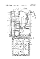
FIG. 1 is a partly sectioned side view of a light display device in accordance with the invention;
FIG. 2 is a section, on a substantial reduction in scale, taken approximately along the indicated line 2--2 of FIG. 1;
FIG. 3 is an exploded view of the device;
and
FIG. 4 is a somewhat schematic and much simplified view illustrating the functioning of the components of the device.
THE PREFERRED EMBODIMENT OF THE INVENTION
The light display device illustrated by the drawings has an open ended box or housing, generally indicated at 5 which is shown as consisting of a bottom 5A in the form of a channel that is rectangular in cross section and a cover 5B. The bottom 5A and the cover 5B are provided with vertically aligned slots of channels 6, 7, and 8.
The slots 6 receive and hold a window 9 of the one way type which closes the front of the box 5 and a sheet, either glass or plastic, and disposed so that its rear surface functions as a mirror. The slots 7 receive and support a like one way window 10 so disposed that the rear surface functions as a mirror while the sots 8 receive and support a mirror 11 facing the front of the box. The mirror 11 is a partition dividing the box 5 into front and rear sections.
The other or rear end of the box is closed by a plate 12 to the interior of which is secured a motor 13 and a lamp 14. The plate 12 has a port 15 through which a cord 16 extends with its leads 16A and 16B at one end connected to the corresponding leads of the motor and lamp and with the other lead ends connected to a plug 17.
The shaft 18 of the motor 13 extends freely through the one way mirror 11 and the one way sheet 10 between which there is a first or front cam 19 and a second or rear cam 20 both of which are of transparent material and are fast on the shaft 18 with a spacer 21 between them. The two cams differ both in size and shape and in function. The lobes 20A of the cam 20 are shown as arcuate and four in number and uniform in shape and in radial extent. The lobes of the cam 19 are shown as seven in number and as uniform in radial extent. As each varies in size and shape from any other, the lobes are designated 19A, 19B, 19C, 19D, 19E, 19F, and 19G and their path is outside the path of the lobes 20A.
The motor shaft 18 also carries a wheel or disc 22 having sections, see FIG. 3, of different colors. The color wheel is located between the lamp 14 and a holder 23 which is provided with a lens 24 and is held by a bracket 25 shown as attached to the rear of the mirror 11. The holder 23 unites as a bundle corresponding ends of a substantial number of optical fibers including a first inner circular series of fibers 26 concentric with the shaft 18, a second, outer concentric series of fibers 27 and a third series of fibers 28. The fibers of each series extend through the mirror 11 and are held thereby parallel to the shaft 18 and the fibers of each series are of a diameter appropriate for their length to provide free ends in the front section of the box 5 that are resilient and have normal positions at right angles to the window 9.
The optical fibers 26 are disposed with their free ends in the path of the lobes 20A of the cam 20 and terminating short of the one way window 10 while the free ends of the fibers 27 are outside the path of the lobes of the cam 20 and extend forwardly in the path of the lobes of the cam 19 through radial slots 29 in the window 10 and terminate short of the front window 9. The inner end of each slot 29 accommodate the associated fiber 27 when unflexed while its outer slot end limits the extent to which the fibers 27 can be displaced.
In operation, with the color disc 22 and the cams 19 and 20 rotating together, the free ends of the fibers 26 are displaced by the lobes of the cam 20 along substantially regular paths determined by the cam lobes 20A while the free ends of the fibers 27 confined within the slots 29 of the window 10 are displaced radially for a distance and interval determined by the size and shape of the lobes of the cam 19 each of which is shown as differing from the others.
While the free ends of the fibers 27 are confined in the slots 29 so that the extent of their travel under the influence of the lobes of the cam 19 is limited, the lobes are so formed as to affect their movement in both directions in their slots in various ways as determined by the leading and trailing edges of each lobe and the junction between the trailing edge of each cam lobe and the leading edge of the next adjacent cam lobe.
While, in the disclosed embodiment and, as is preferred, each lobe of the cam 19 differs from the others, all the differences between the seven cam lobes wll not be detailed. By way of example, however, the cam lobes 19A and 19E may be compared to illustrate how different rates of filament travel are effected by their respective leading and trailing surfaces. In the case of the cam lobe 19E, the leading and trailing edges are substantially identical. In the case of the cam lobe 19A, its leading edge is similar to but shorter than the leading edge of the cam lobe 19E and its trailing edge is such that the optical fiber 27 engaged by that lobe is free to return by its inherent resiliency to the inner end of the slot 29 by which it is confined. Thus the leading and trailing edgs of each cam lobe control the rate of travel of the filaments 27 which they successively engage and the rate of travel controlled by each edge may be varied. Note that both the leading and trailing edges of the cam lobe 19B provide a substantially uniform rate of travel of a fiber end 27 that is faster than that effected by the corresponding surfaces of the cam lobe 19E.
It should also be noted that while the trailing edge of the lobe 19G and the leading edge of the lobe 19H so merge that the fiber end 27 between them travels substantially continuously, the junction of said edges being spaced radially with respect to the shaft axis to have a circular path just inside the normal positions of the fibers 27. In the disclosed embodiment of the invention, the other merging leading and trailing edges of adjacent lobes define dwells enabling the fiber end or ends 27 between them to be at rest for intervals that vary.
The consequences of the action of the cams 19 and 20 are schematically illustrated in FIG. 4. When any of the fiber ends is disposed normal to the mirrors, light is transmitted directly through the one way sheet or sheets in front of it. When, however, the free ends of the fibers 26 are deflected by the lobes 20A, light is also reflected by the rear surfaces of the windows 9 and 10 with the reflected light also again reflected by the mirror 11. In the case of the fiber ends 27, light therefrom is transmitted directly through the window 9 until those fiber ends are reflected radially by the lobes of the cam 19, light then being both reflected and transmitted by the window 10 and the reflected light again reflected by the mirrors 11. In FIG. 4, the reflected light ray patterns are greatly simplified as it will be appreciated that the extent of the reflection is substantially infinite so that only primary paths of the reflected rays is indicated.
In the disclosed embodiment, there are eight optical fibers 26, sixteen optical fibers 27, and sixteen optical fibers 28 but due to the use of reflective surfaces, the effect is that of myriad moving pin points of light.
It will be appreciated that, when the box is viewed from in front, only the lit ends of the fibers are visible as in practice and as is preferred, the opacity of at least the front window 9 is such as to make the fibers invisible so that a shadow box effect is created. The positions of the lit fiber ends 28 are constant and the lit fiber ends 26 constantly move in a substantially regular manner while the lit fiber ends 27 travel erratically with all lit ends appearing as pin points of light in space of constantly changing color.

Claims (13)

We claim:
1. A device for displaying the lit ends of optical fibers, said device including a box provided with a transverse partition dividing the box into front and rear sections, the front of the box a window of one way sheet material, optical fibers extending through said partition with their ends in the front section free, resilient, parallel and at right angles to said window and their ends in the rear section in the form of a bundle, means in said rear section operable to direct light against the bundled ends of the fibers, and means in the front section of the box operable to effect the displacement of and the return of the free ends of at least some of the fibers thereby to produce the effect, when the lit free ends of the fibers are viewed through the window, of pin points of light moving in space.
2. The device of claim 1 in which the opacity of the window is such that only the free ends of the fibers, when lit, are visible through the window.
3. The device of claim 1 in which the partition is a mirror parallel to and facing the window.
4. The device of claim 1 in which the means in the rear section is operable to direct light of constantly changing color against the bundled ends of the fibers.
5. The device of claim 1 in which some of the free fiber ends are stationary.
6. The device of claim 1 in which the displacing means includes a shaft extending through the partition, a motor in the rear section is coupled to the rear end of the said shaft, a cam is fixed on said shaft in the front section, and the free ends of the fibers that are to be displaced are arranged as a circular set concentric with the shaft in position to be displaced and released as the cam rotates.
7. The device of claim 6 in which the means operable to direct light against the bundled ends of the fibers includes a lens, a light source mounted in the rear section and a color wheel fast on the shaft and between the light source and the lens.
8. The device of claim 6 in which the cam includes a plurality of identical lobes of a size and shape to effect uniform displacements of the ends of the fibers.
9. The device of claim 6 in which the cam includes a plurality of dissimilar lobes of sizes and shapes to effect irregular displacement of the ends of the fibers.
10. The device of claim 6 and a second cam in the front section and fixed on said shaft rearwardly of the first cam, the maximum radial extent of the second cam less than that of the first cam and the free ends of the fibers that are to be displaced include a second circular set concentric with said first set and positioned to be displaced and released by said second cam, said first cam translucent.
11. The device of claim 10 and a second window of one way sheet material between said first named window and said partition, said second window having a series of apertures concentric with said shaft through which extend the fiber ends that are to be displaced by the first named cam, said apertures shaped and dimensioned to permit wanted movement of said fiber ends.
12. The device of claim 11 in which the apertures are radial slots.
13. The device of claim 12 in which the first cam includes lobes each shaped and dimensioned to effect differing rates of travel of the fiber ends as they travel lengthwise of the slots and the second cam includes lobes shaped and dimensioned to effect uniform travel of the fiber ends of the second set as they are displaced and released.
US06/164,835 1980-06-30 1980-06-30 Optical fibers Expired - Lifetime US4280122A (en)

Priority Applications (1)

Application Number Priority Date Filing Date Title
US06/164,835 US4280122A (en) 1980-06-30 1980-06-30 Optical fibers

Applications Claiming Priority (1)

Application Number Priority Date Filing Date Title
US06/164,835 US4280122A (en) 1980-06-30 1980-06-30 Optical fibers

Publications (1)

Publication Number Publication Date
US4280122A true US4280122A (en) 1981-07-21

Family

ID=22596293

Family Applications (1)

Application Number Title Priority Date Filing Date
US06/164,835 Expired - Lifetime US4280122A (en) 1980-06-30 1980-06-30 Optical fibers

Country Status (1)

Country Link
US (1) US4280122A (en)

Cited By (12)

* Cited by examiner, † Cited by third party
Publication number Priority date Publication date Assignee Title
US4510555A (en) * 1984-02-27 1985-04-09 Kei Mori Ornamental lighting device
US4525711A (en) * 1982-09-03 1985-06-25 Gery Alan R Three-dimensional fiber optic display
WO1987002746A1 (en) * 1985-10-25 1987-05-07 Manfred Englert Device for fixing bar or rod-shaped elements
US4730930A (en) * 1986-06-24 1988-03-15 Technical Arts Corporation Scanning apparatus and method
US5050047A (en) * 1986-10-30 1991-09-17 Stuart L. Moore Assemblies and apparatus for lighting especially spotlighting
US5193901A (en) * 1991-10-04 1993-03-16 Glo-Max Fiber Optics Systems, Inc. Vending machine back light assembly and method
US5237634A (en) * 1992-01-06 1993-08-17 Follis Charles R Fiber laser light projection system
US5546289A (en) * 1993-10-04 1996-08-13 Gordon; Michael D. Lighting system for use in an aquarium
FR2851323A1 (en) * 2003-02-19 2004-08-20 Patrick Simon Lighting system for decoration and advertising purpose, has optical fiber placed at interior of enclosures, where fiber strands passes from reflecting side of plate towards silverless mirror plate for desired effects
US20050135089A1 (en) * 2003-11-26 2005-06-23 Intp, Inc. Fiber optic and LED fountain and method
US20050281025A1 (en) * 2004-06-17 2005-12-22 Coushaine Charles M High density LED array
US7083298B2 (en) 2001-10-03 2006-08-01 Led Pipe Solid state light source

Citations (12)

* Cited by examiner, † Cited by third party
Publication number Priority date Publication date Assignee Title
US1351562A (en) * 1919-09-10 1920-08-31 J B Wadman Illusion apparatus
US2227861A (en) * 1939-12-07 1941-01-07 Nick Mazzone Artificial christmas tree
US3431410A (en) * 1966-07-13 1969-03-04 Donner Electronics Inc Ornamental display
US3536908A (en) * 1968-04-08 1970-10-27 Nat Statham Inc Fiber optic lighting system
US3662381A (en) * 1970-06-08 1972-05-09 Eric Steffens Lighting devices
US3786500A (en) * 1971-08-03 1974-01-15 R Fiorletta Fiber optic translator
US3836911A (en) * 1973-07-16 1974-09-17 Gen Instrument Corp Coding arrangement for fiber optic digital display device
US3962702A (en) * 1974-03-01 1976-06-08 Jenaer Glaswerk Schott & Gen. Optical fiber display device
US4035215A (en) * 1976-04-05 1977-07-12 Allen Industries, Inc. Process for making sound insulation components
US4097917A (en) * 1976-06-07 1978-06-27 Mccaslin Robert E Rotatable light display
DE2806076A1 (en) * 1978-02-14 1979-08-16 Cima Kg Dipl Kfm W Hochmuth Lighting fitting with optically conducting fibre cluster - has tips of fibres lying in same plane to form picture and has light colour changing unit facing end of bundle
GB2028561A (en) * 1978-07-19 1980-03-05 Murakami T Optical fibre illuminating device employing optical fibres

Patent Citations (12)

* Cited by examiner, † Cited by third party
Publication number Priority date Publication date Assignee Title
US1351562A (en) * 1919-09-10 1920-08-31 J B Wadman Illusion apparatus
US2227861A (en) * 1939-12-07 1941-01-07 Nick Mazzone Artificial christmas tree
US3431410A (en) * 1966-07-13 1969-03-04 Donner Electronics Inc Ornamental display
US3536908A (en) * 1968-04-08 1970-10-27 Nat Statham Inc Fiber optic lighting system
US3662381A (en) * 1970-06-08 1972-05-09 Eric Steffens Lighting devices
US3786500A (en) * 1971-08-03 1974-01-15 R Fiorletta Fiber optic translator
US3836911A (en) * 1973-07-16 1974-09-17 Gen Instrument Corp Coding arrangement for fiber optic digital display device
US3962702A (en) * 1974-03-01 1976-06-08 Jenaer Glaswerk Schott & Gen. Optical fiber display device
US4035215A (en) * 1976-04-05 1977-07-12 Allen Industries, Inc. Process for making sound insulation components
US4097917A (en) * 1976-06-07 1978-06-27 Mccaslin Robert E Rotatable light display
DE2806076A1 (en) * 1978-02-14 1979-08-16 Cima Kg Dipl Kfm W Hochmuth Lighting fitting with optically conducting fibre cluster - has tips of fibres lying in same plane to form picture and has light colour changing unit facing end of bundle
GB2028561A (en) * 1978-07-19 1980-03-05 Murakami T Optical fibre illuminating device employing optical fibres

Cited By (14)

* Cited by examiner, † Cited by third party
Publication number Priority date Publication date Assignee Title
US4525711A (en) * 1982-09-03 1985-06-25 Gery Alan R Three-dimensional fiber optic display
US4510555A (en) * 1984-02-27 1985-04-09 Kei Mori Ornamental lighting device
WO1987002746A1 (en) * 1985-10-25 1987-05-07 Manfred Englert Device for fixing bar or rod-shaped elements
US4730930A (en) * 1986-06-24 1988-03-15 Technical Arts Corporation Scanning apparatus and method
US5050047A (en) * 1986-10-30 1991-09-17 Stuart L. Moore Assemblies and apparatus for lighting especially spotlighting
US5193901A (en) * 1991-10-04 1993-03-16 Glo-Max Fiber Optics Systems, Inc. Vending machine back light assembly and method
US5237634A (en) * 1992-01-06 1993-08-17 Follis Charles R Fiber laser light projection system
US5546289A (en) * 1993-10-04 1996-08-13 Gordon; Michael D. Lighting system for use in an aquarium
US7083298B2 (en) 2001-10-03 2006-08-01 Led Pipe Solid state light source
FR2851323A1 (en) * 2003-02-19 2004-08-20 Patrick Simon Lighting system for decoration and advertising purpose, has optical fiber placed at interior of enclosures, where fiber strands passes from reflecting side of plate towards silverless mirror plate for desired effects
US20050135089A1 (en) * 2003-11-26 2005-06-23 Intp, Inc. Fiber optic and LED fountain and method
US6971779B2 (en) * 2003-11-26 2005-12-06 Intp, Inc. Fiber optic and led fountain and method
US20050281025A1 (en) * 2004-06-17 2005-12-22 Coushaine Charles M High density LED array
US7090386B2 (en) * 2004-06-17 2006-08-15 Osram Sylvania Inc. High density LED array

Similar Documents

Publication Publication Date Title
US4280122A (en) Optical fibers
US2507909A (en) Advertising display
EP0611921B1 (en) Apparatus for simulating flames or a solid fuel fire
US4139955A (en) Display device
US2640144A (en) Indicator illuminating device
US3030856A (en) Kaleidoscope projecting apparatus
US4417412A (en) Fiber optic display device
US3780463A (en) Illuminated displays and illuminaries
US3679888A (en) Variable light projection apparatus
US3208174A (en) Illumination devices
US3747243A (en) Advertising device with flickering light effect
US5111183A (en) Third brake lamp employing optical fibers
GB1374995A (en) Optical arrangement
US4357771A (en) Optical filter device
US2915843A (en) Sign
US3205598A (en) Devices for the production of multiple images
WO2005059443A1 (en) Display arrangement
US2147959A (en) Illuminated indicium
US2670400A (en) Synchronized rotating color filters
US2300447A (en) Animated sign
US2811798A (en) Display device
US1914562A (en) Advertising device
GB1507883A (en) Fibre optic display
EP0080852B1 (en) Display arrangements
US2170368A (en) Illuminated advertising apparatus with a scintillating effect

Legal Events

Date Code Title Description
STCF Information on status: patent grant

Free format text: PATENTED CASE

AS Assignment

Owner name: FIRST NATIONAL BANK OF BOSTON, THE, AS AGENT

Free format text: SECURITY INTEREST;ASSIGNOR:DOLAN-JENNER INDUSTRIES, INC.;REEL/FRAME:004883/0492

Effective date: 19880509

AS Assignment

Owner name: UNITED STATES TRUST COMPANY A MA COMPANY

Free format text: ASSIGNMENT OF ASSIGNORS INTEREST.;ASSIGNOR:DOLAN-JENNER INDUSTRIES, INC. A CORP. MA;REEL/FRAME:005238/0309

Effective date: 19900124

AS Assignment

Owner name: DOLAN-JENNER INDUSTRIES, INC., 99 BLUEBERRY HILL R

Free format text: RELEASED BY SECURED PARTY;ASSIGNOR:FIRST NATIONAL BANK OF BOSTON, THE;REEL/FRAME:005271/0362

Effective date: 19900323