US4292590A - Magnetometer apparatus with detector immobilized in wax - Google Patents
Magnetometer apparatus with detector immobilized in wax Download PDFInfo
- Publication number
- US4292590A US4292590A US06/093,329 US9332979A US4292590A US 4292590 A US4292590 A US 4292590A US 9332979 A US9332979 A US 9332979A US 4292590 A US4292590 A US 4292590A
- Authority
- US
- United States
- Prior art keywords
- detector
- magnetometer
- coil
- housing
- assembly
- Prior art date
- Legal status (The legal status is an assumption and is not a legal conclusion. Google has not performed a legal analysis and makes no representation as to the accuracy of the status listed.)
- Expired - Lifetime
Links
Images


Classifications
-
- G—PHYSICS
- G01—MEASURING; TESTING
- G01R—MEASURING ELECTRIC VARIABLES; MEASURING MAGNETIC VARIABLES
- G01R33/00—Arrangements or instruments for measuring magnetic variables
- G01R33/02—Measuring direction or magnitude of magnetic fields or magnetic flux
- G01R33/04—Measuring direction or magnitude of magnetic fields or magnetic flux using the flux-gate principle
- G01R33/045—Measuring direction or magnitude of magnetic fields or magnetic flux using the flux-gate principle in single-, or multi-aperture elements
-
- G—PHYSICS
- G01—MEASURING; TESTING
- G01R—MEASURING ELECTRIC VARIABLES; MEASURING MAGNETIC VARIABLES
- G01R33/00—Arrangements or instruments for measuring magnetic variables
- G01R33/02—Measuring direction or magnitude of magnetic fields or magnetic flux
-
- G—PHYSICS
- G12—INSTRUMENT DETAILS
- G12B—CONSTRUCTIONAL DETAILS OF INSTRUMENTS, OR COMPARABLE DETAILS OF OTHER APPARATUS, NOT OTHERWISE PROVIDED FOR
- G12B5/00—Adjusting position or attitude, e.g. level, of instruments or other apparatus, or of parts thereof; Compensating for the effects of tilting or acceleration, e.g. for optical apparatus
Definitions
- the invention in general relates to magnetic detection devices, and particularly to a magnetometer assembly.
- a magnetometer is an instrument for measuring the intensity of a magnetic field.
- One widely used magnetometer is of the type which provides an output signal indicative of the change in the earth's magnetic field at a particular location, and more particularly the vertical component of the earth's magnetic field.
- the magnetometer may be secured in a permanent location with a vertical orientation so as to detect disturbances in the vertical component of the earth's magnetic field, which for example may be caused by the relative proximity of a magnetic object.
- the structure to which the magnetometer is attached may not have the proper orientations so as to allow the magnetometer to be absolutely vertical. Accordingly, for such situations, the magnetometer assembly includes a housing having a magnetometer therein which is supported by a gimbal arrangement which allows the magnetometer to orient itself vertically if the supporting structure moves.
- the magnetometer in such gimbaled arrangement is subject to damage during shipment unless special precautions are taken. This may represent a time consuming and relatively expensive procedure.
- the magnetometer assembly of the present invention obviates these disadvantages.
- the assembly includes a housing containing a magnetometer detector to sense external magnetic disturbances.
- the detector is supported in a manner so that it may swing freely so as to assume a vertical orientation.
- the detector is suspended in a material which is a solid at the normal operating temperature of the detector so as to prevent swinging movement, but is a liquid at a relatively higher temperature so as to allow swinging movement.
- Means are also provided for heating the material to the higher temperature. In this manner the material is kept in its solid state during shipment, is heated during installation so as to allow the magnetometer detector to assume a vertical orientation and is thereafter a solid during normal intended operation.
- FIG. 1 is a sectional view of a test range for obtaining a ship's magnetic signature, utilizing a magnetometer assemblies;
- FIG. 2 is a view of a device as illustrated in FIG. 1, with a portion cut away to show a magnetic assembly therein;
- FIG. 3 illustrates yet another use for the magnetometer assembly of the present invention
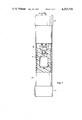
- FIG. 4 is a view partially in section and partially broken away of one embodiment of the present invention.
- FIG. 5 is a further view of the gimbal arrangement for the magnetometer device used in the assembly
- FIG. 6 is a circuit diagram illustrating the operation of the magnetometer device and the present invention.
- FIG. 7 is a view as in FIG. 4 further illustrating another embodiment.
- FIG. 1 illustrates one typical use for magnetometer assemblies.
- the magnetic signature of the ship is obtained by having the ship relatively move past an array of magnetometer assemblies.
- ship 10 has just passed over an array 12 of magnetometer assemblies contained in protective tubes 14.
- the output signals from the respective magnetometer assemblies due to the passage and proximity of the ship 10 are provided by means of cables 16 to a monitoring station 18 whereby the magnetic signature for the ship may then be obtained.
- FIG. 2 a magnetometer assembly 20 is seen positioned within protective tube 14 made of non-magnetic material, such as a fiberglass or plastic.
- Protective tube 14 has a pointed end section 22 to assist during the insertion of the tube into the bed of the body of water.
- the tubes are made as nearly vertical as possible so that the magnetometer assemblies, and particularly the detector portion thereof can assume a vertical position for measuring the vertical component of the earth's magnetic field.
- FIG. 3 Another use for the magnetometer assembly is illustrated in FIG. 3 wherein a magnetometer assembly package 24 is affixed to a structure 26.
- the package 24 is mounted so as to assume a vertical position and any tilting movement by the structure 26 will cause a corresponding output signal from the magnetometer assembly which by virtue of its connection to the structure will tilt with it thus assuming a different orientation with respect to the vertical component of the earths magnetic field.
- FIG. 4 A magnetometer assembly in accordance with the present invention for performing such measurements is illustrated in FIG. 4.
- the magnetometer assembly 20 includes a magnetometer detector 30 contained within a housing member in the form of a tube 32 symmetrically disposed about a central axis A and having top and bottom end caps 34 and 35. If utilized in an environment where the ambient medium is a liquid, a weight 37 may be provided at the lower portion of the assembly to impart negative buoyancy.
- the magnetometer detector 30 is mounted within the housing 32 so as to swing freely, this action being provided by means of a gimbal assembly 40 which in a well known manner and as illustrated in FIG. 5 allows rotation about mutually orthogonal axes x and y.
- the gimbal assembly 40 is supported at the lower end of a printed circuit board 42 containing electronic components 44 utilized in the operation of the magnetometer detector 30.
- the printed circuit assembly 42 is in turn supported by means of bracket 46 connected to the top end cap 34.
- a socket arrangement 48 is operable to conduct power and signals to and from the magnetometer assembly by way of cable 16.
- the housing 32 contains a material 50 in which the magnetometer detector is suspended.
- the material 50 is of the type which is a solid at the normal operating temperature of the detector so as to prevent swinging movement of it but is a liquid at a relatively higher temperature to allow the detector to assume a vertical position for its operation.
- Various mineral waxes having the appropriate melting point are suitable for use as the material and may be introduced into the housing 32 while in a liquid state to a level preferably covering the gimbal assembly 40.
- the magnetometer assembly when the material is a solid state, the magnetometer assembly may be handled and be subjected to shock and vibration without the magnetometer detector banging into the housing since the solidified wax holds the detector solidly with respect to the housing.
- heat is applied to material 50 to melt it at least at the vicinity of the magnetometer detector 30 so as to allow gimbaled movement thereof and the assumption of a vertical orientation. Thereafter the heat is removed to return material 50 to its solidified form so that any output from detector 30 represents a magnetic disturbance caused either by a relative tilting of the assembly 20 or the proximity of a magnetic object.
- FIG. 6 illustrates one means for performing the heating operation to melt the material in the vicinity of the detector.
- the detector 30 includes a toroidal core 60 having a torodial winding 62 thereabout supplied with an AC drive signal from drive source 64, the signal having a frequency f 1 .
- a solonoid or sense winding 66 is wound about the core 60 and winding 62 and coil 68 utilized for nulling the effects of the earth's magnetism is also included.
- Each cycle of the drive signal of frequency f 1 drives the toroidal core 60 into positive and negative saturation which has the effect of modulating any external magnetic field with a frequency 2f 1 .
- the modulation of the magnetic field results in an output signal provided by sense winding 66.
- a small current is provided to coil 68 so as to provide a magnetic field equal and opposite to the earth's magnetic field so that in the normal quiescent operating condition sense winding 66 provides no output signal.
- phase or synchronous detector 76 which is additionally provided with a signal of frequency 2f 1 from drive circuit 64, this frequency being the same as that of the other signal provided to phase detector 76.
- Phase detector 76 in effect operates as an electronic switch which is provided with a gating signal from drive source 64 to gate the signal from amplifier 74 to an intergrator 78, the output signal of which is fed back via line 80 to the sense winding 66.
- the integrator output signal fed back to the sense winding 66 drives a current through the winding to counteract and nullify the disturbance whereupon the former output signal of sense winding 66, and therefore the input to phase detector 76 and its output to integrator 78 goes to zero.
- the voltage at the output 82 of the integrator 78 therefore is indicative of how much signal was fed back to counteract the change, and consequently is indicative of the magnitude of the change.
- a power source 90 is provided for supplying a relatively high current to the existing coil 68 causing it to generate heat of sufficient value so as to liquify material 50 surrounding the detector 30.
- Manually or electrically operable switch means 92 is provided for selecting power supply 90 to be connected to coil 68 for initial installation of the apparatus and thereafter for selecting the lower and adjustable current for initial and continual nullification of the earth's magnetic field.
- FIG. 7 illustrates another means by which the material 50 may be heated to its higher temperature to cause melting thereof.
- the embodiment of FIG. 7 includes a heating coil 94 which preferably is located within housing 32 so as to allow operation in a water medium.
- Coil 94 is disposed around magnetometer detector 30 and is spaced therefrom so as to allow gimbal action when material 50 is in its liquified state in the vicinity of detector 30.
- Current for heating coil 94 may be supplied via cable 16.
Abstract
A magnetometer assembly wherein a magnetometer detector suspended from a gimbal is immersed in a wax so as to immobilize the detector. Desired gimbal operation is achieved by heating the wax in the vicinity of the detector.
Description
1. Field of the Invention
The invention in general relates to magnetic detection devices, and particularly to a magnetometer assembly.
2. Description of the Prior Art
A magnetometer is an instrument for measuring the intensity of a magnetic field. One widely used magnetometer is of the type which provides an output signal indicative of the change in the earth's magnetic field at a particular location, and more particularly the vertical component of the earth's magnetic field.
The magnetometer may be secured in a permanent location with a vertical orientation so as to detect disturbances in the vertical component of the earth's magnetic field, which for example may be caused by the relative proximity of a magnetic object.
In many instances, the structure to which the magnetometer is attached may not have the proper orientations so as to allow the magnetometer to be absolutely vertical. Accordingly, for such situations, the magnetometer assembly includes a housing having a magnetometer therein which is supported by a gimbal arrangement which allows the magnetometer to orient itself vertically if the supporting structure moves.
A problem arises however in that any lateral movement of the holding structure causes the gimbaled magnetometer to swing, thus providing an erroneous output signal.
Further, the magnetometer in such gimbaled arrangement is subject to damage during shipment unless special precautions are taken. This may represent a time consuming and relatively expensive procedure.
The magnetometer assembly of the present invention obviates these disadvantages. The assembly includes a housing containing a magnetometer detector to sense external magnetic disturbances. The detector is supported in a manner so that it may swing freely so as to assume a vertical orientation. The detector is suspended in a material which is a solid at the normal operating temperature of the detector so as to prevent swinging movement, but is a liquid at a relatively higher temperature so as to allow swinging movement. Means are also provided for heating the material to the higher temperature. In this manner the material is kept in its solid state during shipment, is heated during installation so as to allow the magnetometer detector to assume a vertical orientation and is thereafter a solid during normal intended operation.
FIG. 1 is a sectional view of a test range for obtaining a ship's magnetic signature, utilizing a magnetometer assemblies;
FIG. 2 is a view of a device as illustrated in FIG. 1, with a portion cut away to show a magnetic assembly therein;
FIG. 3 illustrates yet another use for the magnetometer assembly of the present invention;
FIG. 4 is a view partially in section and partially broken away of one embodiment of the present invention;
FIG. 5 is a further view of the gimbal arrangement for the magnetometer device used in the assembly;
FIG. 6 is a circuit diagram illustrating the operation of the magnetometer device and the present invention; and
FIG. 7 is a view as in FIG. 4 further illustrating another embodiment.
FIG. 1 illustrates one typical use for magnetometer assemblies. In order to determine what effect a ship will have on the earth's magnetic field, in particular the vertical component of the field, due to its own magnetism, the magnetic signature of the ship is obtained by having the ship relatively move past an array of magnetometer assemblies. In FIG. 1 ship 10 has just passed over an array 12 of magnetometer assemblies contained in protective tubes 14. The output signals from the respective magnetometer assemblies due to the passage and proximity of the ship 10 are provided by means of cables 16 to a monitoring station 18 whereby the magnetic signature for the ship may then be obtained.
In FIG. 2 a magnetometer assembly 20 is seen positioned within protective tube 14 made of non-magnetic material, such as a fiberglass or plastic. Protective tube 14 has a pointed end section 22 to assist during the insertion of the tube into the bed of the body of water. During the insertion phase the tubes are made as nearly vertical as possible so that the magnetometer assemblies, and particularly the detector portion thereof can assume a vertical position for measuring the vertical component of the earth's magnetic field. Some degree of error however is allowable since the detector portion in many types of assemblies is, as will be seen, mounted to swing freely to assume a vertical orientation.
Another use for the magnetometer assembly is illustrated in FIG. 3 wherein a magnetometer assembly package 24 is affixed to a structure 26. The package 24 is mounted so as to assume a vertical position and any tilting movement by the structure 26 will cause a corresponding output signal from the magnetometer assembly which by virtue of its connection to the structure will tilt with it thus assuming a different orientation with respect to the vertical component of the earths magnetic field. A magnetometer assembly in accordance with the present invention for performing such measurements is illustrated in FIG. 4.
The magnetometer assembly 20 includes a magnetometer detector 30 contained within a housing member in the form of a tube 32 symmetrically disposed about a central axis A and having top and bottom end caps 34 and 35. If utilized in an environment where the ambient medium is a liquid, a weight 37 may be provided at the lower portion of the assembly to impart negative buoyancy.
The magnetometer detector 30 is mounted within the housing 32 so as to swing freely, this action being provided by means of a gimbal assembly 40 which in a well known manner and as illustrated in FIG. 5 allows rotation about mutually orthogonal axes x and y.
Referring once again to FIG. 4, the gimbal assembly 40 is supported at the lower end of a printed circuit board 42 containing electronic components 44 utilized in the operation of the magnetometer detector 30. The printed circuit assembly 42 is in turn supported by means of bracket 46 connected to the top end cap 34. A socket arrangement 48 is operable to conduct power and signals to and from the magnetometer assembly by way of cable 16.
In accordance with the present invention, the housing 32 contains a material 50 in which the magnetometer detector is suspended. The material 50 is of the type which is a solid at the normal operating temperature of the detector so as to prevent swinging movement of it but is a liquid at a relatively higher temperature to allow the detector to assume a vertical position for its operation. Various mineral waxes having the appropriate melting point are suitable for use as the material and may be introduced into the housing 32 while in a liquid state to a level preferably covering the gimbal assembly 40.
Thus, when the material is a solid state, the magnetometer assembly may be handled and be subjected to shock and vibration without the magnetometer detector banging into the housing since the solidified wax holds the detector solidly with respect to the housing. During installation, heat is applied to material 50 to melt it at least at the vicinity of the magnetometer detector 30 so as to allow gimbaled movement thereof and the assumption of a vertical orientation. Thereafter the heat is removed to return material 50 to its solidified form so that any output from detector 30 represents a magnetic disturbance caused either by a relative tilting of the assembly 20 or the proximity of a magnetic object.
FIG. 6 illustrates one means for performing the heating operation to melt the material in the vicinity of the detector. In one form the detector 30 includes a toroidal core 60 having a torodial winding 62 thereabout supplied with an AC drive signal from drive source 64, the signal having a frequency f1. A solonoid or sense winding 66 is wound about the core 60 and winding 62 and coil 68 utilized for nulling the effects of the earth's magnetism is also included. Each cycle of the drive signal of frequency f1 drives the toroidal core 60 into positive and negative saturation which has the effect of modulating any external magnetic field with a frequency 2f1. The modulation of the magnetic field results in an output signal provided by sense winding 66. In order to increase the sensitivity, of the apparatus, a small current, the value of which is adjustable by potentiometer 70, is provided to coil 68 so as to provide a magnetic field equal and opposite to the earth's magnetic field so that in the normal quiescent operating condition sense winding 66 provides no output signal.
Should the magnetic field thereafter change due to a different orientation of the detector or the presence of a disturbing magnetic influence, there will result an output signal from sense winding 66 which is coupled by means of capacitor 72 to amplifier 74. The amplified signal is provided to a phase or synchronous detector 76 which is additionally provided with a signal of frequency 2f1 from drive circuit 64, this frequency being the same as that of the other signal provided to phase detector 76. Phase detector 76 in effect operates as an electronic switch which is provided with a gating signal from drive source 64 to gate the signal from amplifier 74 to an intergrator 78, the output signal of which is fed back via line 80 to the sense winding 66. The integrator output signal fed back to the sense winding 66 drives a current through the winding to counteract and nullify the disturbance whereupon the former output signal of sense winding 66, and therefore the input to phase detector 76 and its output to integrator 78 goes to zero. The voltage at the output 82 of the integrator 78 therefore is indicative of how much signal was fed back to counteract the change, and consequently is indicative of the magnitude of the change.
In one embodiment of the present invention, a power source 90 is provided for supplying a relatively high current to the existing coil 68 causing it to generate heat of sufficient value so as to liquify material 50 surrounding the detector 30. Manually or electrically operable switch means 92 is provided for selecting power supply 90 to be connected to coil 68 for initial installation of the apparatus and thereafter for selecting the lower and adjustable current for initial and continual nullification of the earth's magnetic field.
FIG. 7 illustrates another means by which the material 50 may be heated to its higher temperature to cause melting thereof. The embodiment of FIG. 7 includes a heating coil 94 which preferably is located within housing 32 so as to allow operation in a water medium. Coil 94 is disposed around magnetometer detector 30 and is spaced therefrom so as to allow gimbal action when material 50 is in its liquified state in the vicinity of detector 30. Current for heating coil 94 may be supplied via cable 16.
Claims (7)
1. A magnetometer assembly comprising:
(a) a housing;
(b) a magnetometer detector disposed within said housing to sense external magnetic disturbances;
(c) support means for supporting said detector and being of the type which allows said detector to swing freely so as to assume a vertical orientation;
(d) said detector being suspended in a material which is a solid at the normal operating temperature of said detector so as to prevent swinging movement of said detector but is a liquid at a relatively higher temperature so as to allow swinging movement of said detector; and
(e) means for heating said material to said higher temperature.
2. Apparatus according to claim 1 wherein:
(a) said support means is a gimbal which allows rotation of said detector about two mutually perpendicular axes; and wherein,
(b) said material covers said gimbal.
3. Apparatus according to claim 1 wherein:
(a) said material is a wax.
4. Apparatus according to claim 1 wherein:
(a) said detector includes an electrical coil normally used for nulling the effects of the earth's magnetism; and which includes;
(b) means for supplying said coil with electrical energy to generate heat of sufficient values so as to liquify said material.
5. Apparatus according to claim 1 wherein:
(a) said means for heating includes a heating coil disposed within said housing.
6. Apparatus according to claim 5 wherein:
(a) said coil is disposed around said detector.
7. Apparatus according to claim 6 wherein:
(a) said coil is spaced from said detector.
Priority Applications (7)
| Application Number | Priority Date | Filing Date | Title |
|---|---|---|---|
| US06/093,329 US4292590A (en) | 1979-11-13 | 1979-11-13 | Magnetometer apparatus with detector immobilized in wax |
| CA000363081A CA1146630A (en) | 1979-11-13 | 1980-10-23 | Magnetometer apparatus |
| KR1019800004250A KR830001110B1 (en) | 1979-11-13 | 1980-11-05 | Magnetometer |
| GB8035877A GB2063483B (en) | 1979-11-13 | 1980-11-07 | Magnetometer apparatus |
| IT25904/80A IT1134216B (en) | 1979-11-13 | 1980-11-12 | MAGNETOMETER |
| JP15891480A JPS5684574A (en) | 1979-11-13 | 1980-11-13 | Magnetic force meter |
| DE19803042861 DE3042861A1 (en) | 1979-11-13 | 1980-11-13 | MAGNETOMETER DEVICE |
Applications Claiming Priority (1)
| Application Number | Priority Date | Filing Date | Title |
|---|---|---|---|
| US06/093,329 US4292590A (en) | 1979-11-13 | 1979-11-13 | Magnetometer apparatus with detector immobilized in wax |
Publications (1)
| Publication Number | Publication Date |
|---|---|
| US4292590A true US4292590A (en) | 1981-09-29 |
Family
ID=22238340
Family Applications (1)
| Application Number | Title | Priority Date | Filing Date |
|---|---|---|---|
| US06/093,329 Expired - Lifetime US4292590A (en) | 1979-11-13 | 1979-11-13 | Magnetometer apparatus with detector immobilized in wax |
Country Status (7)
| Country | Link |
|---|---|
| US (1) | US4292590A (en) |
| JP (1) | JPS5684574A (en) |
| KR (1) | KR830001110B1 (en) |
| CA (1) | CA1146630A (en) |
| DE (1) | DE3042861A1 (en) |
| GB (1) | GB2063483B (en) |
| IT (1) | IT1134216B (en) |
Cited By (19)
| Publication number | Priority date | Publication date | Assignee | Title |
|---|---|---|---|---|
| US4388592A (en) * | 1980-06-24 | 1983-06-14 | Schonstedt Instrument Company | Multiaxis magnetometer apparatus with orthogonally disposed rectangular housings for mounting separate sensor assemblies |
| US4539522A (en) * | 1982-06-23 | 1985-09-03 | Schonstedt Instrument Company | Magnetic detector apparatus with liquid-supported, conductive, sensor-support tube |
| US4590425A (en) * | 1982-06-23 | 1986-05-20 | Schonstedt Instrument Company | Magnetic detector apparatus with excitation conductors connected in series via sensor housing |
| US4600969A (en) * | 1984-07-06 | 1986-07-15 | Hendrickson Max S | Protective apparatus for encapsulating electrical circuits |
| US4694119A (en) * | 1983-09-07 | 1987-09-15 | Sundstrand Data Control, Inc. | Heat shielded memory unit for an aircraft flight data recorder |
| US4712094A (en) * | 1986-05-29 | 1987-12-08 | Minnesota Mining And Manufacturing Company | Self-orienting passive marker structure |
| US4812759A (en) * | 1985-06-14 | 1989-03-14 | Thomson-Csf | Method for measuring and correcting the induced magnetization in a nautical vessel |
| US5015801A (en) * | 1988-05-11 | 1991-05-14 | Schaller-Automation, Industrielle Automationstechnik Kg | Electrical circuit module |
| US5080190A (en) * | 1991-06-14 | 1992-01-14 | Southwest Research Institute | Reversible rigid coupling apparatus and method for borehole seismic transducers |
| US5327089A (en) * | 1992-09-30 | 1994-07-05 | Raytheon Company | Portable assembly for supporting magnetic and electrical sensors |
| US5570023A (en) * | 1991-07-23 | 1996-10-29 | Thomson-Csf | Portable station for measuring and adjusting the magnetic signature of a naval ship |
| US5699048A (en) * | 1996-10-03 | 1997-12-16 | Industrial Technology Inc. | Omnidirectional passive electrical marker for underground use |
| US5955954A (en) * | 1997-06-19 | 1999-09-21 | Wandel & Goltermann Management Holding Gmbh | Warning and measuring device for personal protection in electromagnetic fields |
| US6097293A (en) * | 1999-04-15 | 2000-08-01 | Industrial Technology, Inc. | Passive electrical marker for underground use and method of making thereof |
| WO2001065280A1 (en) * | 2000-03-01 | 2001-09-07 | Geco As | A seismic sensor |
| US6380857B1 (en) | 2000-10-16 | 2002-04-30 | Industrial Technology, Inc. | Self leveling underground marker |
| US6388575B1 (en) | 1999-11-05 | 2002-05-14 | Industrial Technology, Inc. | Addressable underground marker |
| US20040075577A1 (en) * | 2001-01-25 | 2004-04-22 | Victor Allan | Induction logging antenna |
| US10705249B2 (en) | 2018-05-23 | 2020-07-07 | Joe T. Minarovic | Electronic marker with integral level indicator |
Families Citing this family (2)
| Publication number | Priority date | Publication date | Assignee | Title |
|---|---|---|---|---|
| DE3134811C1 (en) * | 1981-09-03 | 1999-02-18 | Stn Atlas Elektronik Gmbh | Arrangement for determining the spatial variation of magnetic field gradients |
| DE4419355A1 (en) * | 1994-06-03 | 1995-12-07 | Telefunken Microelectron | Detection of road or rail vehicles for traffic monitoring |
Citations (6)
| Publication number | Priority date | Publication date | Assignee | Title |
|---|---|---|---|---|
| US1240872A (en) * | 1915-11-10 | 1917-09-25 | John Perry | Gyro-compass. |
| US2687507A (en) * | 1950-09-29 | 1954-08-24 | Erick O Schonstedt | Method and apparatus for measuring the earth's total magnetic field vector |
| US2951375A (en) * | 1954-02-24 | 1960-09-06 | Summers Gyroscope Company | Rate integrating gyro |
| US3115784A (en) * | 1961-06-28 | 1963-12-31 | Gen Precision Inc | Free rotor gas bearing gyro |
| US3283592A (en) * | 1961-08-04 | 1966-11-08 | Sperry Rand Corp | Gyroscopic caging apparatus |
| US3790882A (en) * | 1972-11-30 | 1974-02-05 | Coniagas Research Inc | Dip magnet magnetometer having a damped pendulous support and temperature compensation |
-
1979
- 1979-11-13 US US06/093,329 patent/US4292590A/en not_active Expired - Lifetime
-
1980
- 1980-10-23 CA CA000363081A patent/CA1146630A/en not_active Expired
- 1980-11-05 KR KR1019800004250A patent/KR830001110B1/en active
- 1980-11-07 GB GB8035877A patent/GB2063483B/en not_active Expired
- 1980-11-12 IT IT25904/80A patent/IT1134216B/en active
- 1980-11-13 JP JP15891480A patent/JPS5684574A/en active Pending
- 1980-11-13 DE DE19803042861 patent/DE3042861A1/en not_active Withdrawn
Patent Citations (6)
| Publication number | Priority date | Publication date | Assignee | Title |
|---|---|---|---|---|
| US1240872A (en) * | 1915-11-10 | 1917-09-25 | John Perry | Gyro-compass. |
| US2687507A (en) * | 1950-09-29 | 1954-08-24 | Erick O Schonstedt | Method and apparatus for measuring the earth's total magnetic field vector |
| US2951375A (en) * | 1954-02-24 | 1960-09-06 | Summers Gyroscope Company | Rate integrating gyro |
| US3115784A (en) * | 1961-06-28 | 1963-12-31 | Gen Precision Inc | Free rotor gas bearing gyro |
| US3283592A (en) * | 1961-08-04 | 1966-11-08 | Sperry Rand Corp | Gyroscopic caging apparatus |
| US3790882A (en) * | 1972-11-30 | 1974-02-05 | Coniagas Research Inc | Dip magnet magnetometer having a damped pendulous support and temperature compensation |
Cited By (21)
| Publication number | Priority date | Publication date | Assignee | Title |
|---|---|---|---|---|
| US4388592A (en) * | 1980-06-24 | 1983-06-14 | Schonstedt Instrument Company | Multiaxis magnetometer apparatus with orthogonally disposed rectangular housings for mounting separate sensor assemblies |
| US4539522A (en) * | 1982-06-23 | 1985-09-03 | Schonstedt Instrument Company | Magnetic detector apparatus with liquid-supported, conductive, sensor-support tube |
| US4590425A (en) * | 1982-06-23 | 1986-05-20 | Schonstedt Instrument Company | Magnetic detector apparatus with excitation conductors connected in series via sensor housing |
| US4694119A (en) * | 1983-09-07 | 1987-09-15 | Sundstrand Data Control, Inc. | Heat shielded memory unit for an aircraft flight data recorder |
| US4600969A (en) * | 1984-07-06 | 1986-07-15 | Hendrickson Max S | Protective apparatus for encapsulating electrical circuits |
| US4812759A (en) * | 1985-06-14 | 1989-03-14 | Thomson-Csf | Method for measuring and correcting the induced magnetization in a nautical vessel |
| US4712094A (en) * | 1986-05-29 | 1987-12-08 | Minnesota Mining And Manufacturing Company | Self-orienting passive marker structure |
| US5015801A (en) * | 1988-05-11 | 1991-05-14 | Schaller-Automation, Industrielle Automationstechnik Kg | Electrical circuit module |
| US5080190A (en) * | 1991-06-14 | 1992-01-14 | Southwest Research Institute | Reversible rigid coupling apparatus and method for borehole seismic transducers |
| US5570023A (en) * | 1991-07-23 | 1996-10-29 | Thomson-Csf | Portable station for measuring and adjusting the magnetic signature of a naval ship |
| US5327089A (en) * | 1992-09-30 | 1994-07-05 | Raytheon Company | Portable assembly for supporting magnetic and electrical sensors |
| US5699048A (en) * | 1996-10-03 | 1997-12-16 | Industrial Technology Inc. | Omnidirectional passive electrical marker for underground use |
| US5955954A (en) * | 1997-06-19 | 1999-09-21 | Wandel & Goltermann Management Holding Gmbh | Warning and measuring device for personal protection in electromagnetic fields |
| US6097293A (en) * | 1999-04-15 | 2000-08-01 | Industrial Technology, Inc. | Passive electrical marker for underground use and method of making thereof |
| US6388575B1 (en) | 1999-11-05 | 2002-05-14 | Industrial Technology, Inc. | Addressable underground marker |
| WO2001065280A1 (en) * | 2000-03-01 | 2001-09-07 | Geco As | A seismic sensor |
| US6751162B2 (en) * | 2000-03-01 | 2004-06-15 | Westerngeco, Llc | Seismic sensor |
| US6380857B1 (en) | 2000-10-16 | 2002-04-30 | Industrial Technology, Inc. | Self leveling underground marker |
| US20040075577A1 (en) * | 2001-01-25 | 2004-04-22 | Victor Allan | Induction logging antenna |
| US7012432B2 (en) * | 2001-01-25 | 2006-03-14 | Geolink (Uk) Ltd. | Induction logging antenna |
| US10705249B2 (en) | 2018-05-23 | 2020-07-07 | Joe T. Minarovic | Electronic marker with integral level indicator |
Also Published As
| Publication number | Publication date |
|---|---|
| IT1134216B (en) | 1986-08-13 |
| GB2063483B (en) | 1983-08-03 |
| IT8025904A0 (en) | 1980-11-12 |
| JPS5684574A (en) | 1981-07-09 |
| GB2063483A (en) | 1981-06-03 |
| DE3042861A1 (en) | 1981-09-03 |
| KR830001110B1 (en) | 1983-06-11 |
| CA1146630A (en) | 1983-05-17 |
Similar Documents
| Publication | Publication Date | Title |
|---|---|---|
| US4292590A (en) | Magnetometer apparatus with detector immobilized in wax | |
| JPS61180127A (en) | Method and device for measuring rheology characteristic of liquid, particularly, liquid of organism such as blood | |
| US2551596A (en) | Aerodynamic body for carrying detection apparatus | |
| US4033045A (en) | Portable surveying gyrocompass apparatus | |
| US4362992A (en) | System and method of detecting the proximity of an alternating magnetic field | |
| US2674885A (en) | Gravity meter motion compensator | |
| US2746301A (en) | Gyroscopic devices | |
| US4894617A (en) | Device for locating steel rods buried in high-density reinforced concrete | |
| Serson | Instrumentation for induction studies on land | |
| US3924261A (en) | Displacement detector using magnetometer sensor | |
| US2946226A (en) | Accelerometers | |
| US2607217A (en) | Viscosity meter | |
| US3510832A (en) | Field homogenization for a reference sample in a lock-on nuclear magnetic resonance apparatus | |
| US3873914A (en) | Flux valve apparatus for sensing both horizontal and vertical components of an ambient magnetic field | |
| US3644823A (en) | Nulling coil apparatus for magnetic susceptibility logging | |
| US2542018A (en) | Compass | |
| US3573610A (en) | Earth{3 s field-sensitive magnetometer for use in compass systems having gradually converging flux collectors and being insensitive to varying ambient temperature | |
| US4806865A (en) | Device for measuring the earth's magnetic field disturbed by anomalies | |
| US5570023A (en) | Portable station for measuring and adjusting the magnetic signature of a naval ship | |
| US3685011A (en) | Seismometer | |
| US2436039A (en) | Magnetic field gradient measurement | |
| US4139950A (en) | Direction responsive flux gate unit | |
| US2451819A (en) | Induction magnetometer | |
| US2969503A (en) | Measurement of potential gradients | |
| US3471777A (en) | Differential magnetometer having parallel rotating fields and associated sensing circuitry |
Legal Events
| Date | Code | Title | Description |
|---|---|---|---|
| STCF | Information on status: patent grant |
Free format text: PATENTED CASE |
|
| AS | Assignment |
Owner name: HOPE INDUSTRIES, INC., A CORP. OF PENNSYLVANIA, PE Free format text: ASSIGNMENT OF ASSIGNORS INTEREST.;ASSIGNORS:HOPE, HENRY F.;HOPE, STEPHEN F.;REEL/FRAME:005285/0464 Effective date: 19890720 |
|
| AS | Assignment |
Owner name: NORTHROP GRUMMAN CORPORATION, CALIFORNIA Free format text: ASSIGNMENT OF ASSIGNORS INTEREST;ASSIGNOR:WESTINGHOUSE ELECTRIC CORPORATION;REEL/FRAME:008104/0190 Effective date: 19960301 |