US4294696A - Swing diffuser - Google Patents
Swing diffuser Download PDFInfo
- Publication number
- US4294696A US4294696A US06/115,470 US11547080A US4294696A US 4294696 A US4294696 A US 4294696A US 11547080 A US11547080 A US 11547080A US 4294696 A US4294696 A US 4294696A
- Authority
- US
- United States
- Prior art keywords
- arm
- array
- hanger arm
- diffuser
- upper hanger
- Prior art date
- Legal status (The legal status is an assumption and is not a legal conclusion. Google has not performed a legal analysis and makes no representation as to the accuracy of the status listed.)
- Expired - Lifetime
Links
Images


Classifications
-
- C—CHEMISTRY; METALLURGY
- C02—TREATMENT OF WATER, WASTE WATER, SEWAGE, OR SLUDGE
- C02F—TREATMENT OF WATER, WASTE WATER, SEWAGE, OR SLUDGE
- C02F3/00—Biological treatment of water, waste water, or sewage
- C02F3/02—Aerobic processes
- C02F3/12—Activated sludge processes
- C02F3/20—Activated sludge processes using diffusers
- C02F3/203—Swing diffusers
-
- B—PERFORMING OPERATIONS; TRANSPORTING
- B01—PHYSICAL OR CHEMICAL PROCESSES OR APPARATUS IN GENERAL
- B01F—MIXING, e.g. DISSOLVING, EMULSIFYING OR DISPERSING
- B01F23/00—Mixing according to the phases to be mixed, e.g. dispersing or emulsifying
- B01F23/20—Mixing gases with liquids
- B01F23/23—Mixing gases with liquids by introducing gases into liquid media, e.g. for producing aerated liquids
- B01F23/231—Mixing gases with liquids by introducing gases into liquid media, e.g. for producing aerated liquids by bubbling
- B01F23/23105—Arrangement or manipulation of the gas bubbling devices
- B01F23/2311—Mounting the bubbling devices or the diffusers
- B01F23/23116—Means for manipulating the bubbling constructions or elements, e.g. for raising or lowering them
-
- Y—GENERAL TAGGING OF NEW TECHNOLOGICAL DEVELOPMENTS; GENERAL TAGGING OF CROSS-SECTIONAL TECHNOLOGIES SPANNING OVER SEVERAL SECTIONS OF THE IPC; TECHNICAL SUBJECTS COVERED BY FORMER USPC CROSS-REFERENCE ART COLLECTIONS [XRACs] AND DIGESTS
- Y02—TECHNOLOGIES OR APPLICATIONS FOR MITIGATION OR ADAPTATION AGAINST CLIMATE CHANGE
- Y02W—CLIMATE CHANGE MITIGATION TECHNOLOGIES RELATED TO WASTEWATER TREATMENT OR WASTE MANAGEMENT
- Y02W10/00—Technologies for wastewater treatment
- Y02W10/10—Biological treatment of water, waste water, or sewage
-
- Y—GENERAL TAGGING OF NEW TECHNOLOGICAL DEVELOPMENTS; GENERAL TAGGING OF CROSS-SECTIONAL TECHNOLOGIES SPANNING OVER SEVERAL SECTIONS OF THE IPC; TECHNICAL SUBJECTS COVERED BY FORMER USPC CROSS-REFERENCE ART COLLECTIONS [XRACs] AND DIGESTS
- Y10—TECHNICAL SUBJECTS COVERED BY FORMER USPC
- Y10S—TECHNICAL SUBJECTS COVERED BY FORMER USPC CROSS-REFERENCE ART COLLECTIONS [XRACs] AND DIGESTS
- Y10S261/00—Gas and liquid contact apparatus
- Y10S261/47—Swing diffusers
Definitions
- the present invention relates to liquid treatment systems of the type in which gas is passed through the liquid to modify it for subsequent uses, such as in sanitary sewage treatment systems where oxidative gases are diffused into waste liquids.
- the invention concerns such systems in which an array of gas diffusers is submerged in the liquid during operation of the system.
- the array is positioned in the tank or vessel containing the liquid by an apparatus, mechanism or linkage which permits lifting the array from its submerged operating position to an open air servicing position adjacent to the side of the tank.
- the combination of such an apparatus and an array of diffusers has become known in the art as a "swing diffuser.”
- Waste liquid treatment systems having various types of swing diffusers have been known since about the mid-1930's.
- One early sewage treatment apparatus comprised an array of diffusers connected to a pivot in the treatment tank at a location below the liquid surface, so that the array could be raised to a servicing position using a chain and sprocket mechanism. In the servicing position, the array extended over and at least partly blocked the walkway provided at the edge of the tank.
- a later, improved apparatus comprised an upper hanger pipe pivoted to an air supply main located on the coping at the edge of the tank above the liquid surface.
- a lower hanger pipe was pivoted to the lower end of the upper hanger pipe, and the diffuser array was rigidly secured to the lower end of the lower hanger pipe. This arrangement permitted movement of the array to a point at which it partly blocked the walkway and partly extended out over the tank, thus making servicing of some of the diffusers rather difficult.
- Complex systems of cables and guide tracks also have been used to raise and lower diffuser arrays.
- Swing diffusers also were developed in which a flexible hose, supported by pivoted upper and lower hanger arms, was attached to a diffuser array rigidly connected to the lower hanger arm. In its raised position, the array remained nearly horizontal so that some diffuser units extended over the edge of the tank, thus making servicing difficult. Even until very recent years, swing diffuser mechanisms have continued to be installed in which pivoted upper and lower hanger arms supported a diffuser array rigidly attached to the lower hanger arm, so that the array remained horizontal and rather difficult to service in its raised position.
- a primary object of the present invention is to provide an improved swing diffuser apparatus in which a large array of diffusers can be easily, safely moved to a servicing position at a location adjacent the edge of the waste liquid tank.
- Another object of the invention is to provide such an apparatus in which the array of diffusers is oriented in the servicing position in an upwardly extending attitude adjacent the edge of the waste liquid tank, thus facilitating safe, effective maintenance of the diffusers making up the array.
- a further object of the invention is to provide such an apparatus which permits the array to be oriented substantially horizontally in operating positions ranging from deeply to rather shallowly submerged positions below the surface of the waste liquid.
- Yet another object of the invention is to provide such an apparatus in which stress levels in the arms comprising the apparatus can be conveniently maintained within desired limits.
- the invention comprises a rigid upper hanger arm, an upper portion of which includes a pivot by which the arm may be secured to a fixed support, such as the edge of a tank of waste liquid.
- a rigid lower arm is also provided, and its upper portion is pivotally connected to the lower portion of the upper arm by a suitable joint so that the major portion or all of the lower arm folds toward the upper arm as the upper arm is raised about its pivot.
- an array of diffusers for oxidative gas is pivotally connected to a lower portion of the lower hanger arm, so that when the upper hanger arm is raised, the array can pivot from its essentially horizontal operating position to a substantially upright servicing position near the edge of the tank.
- the term “upper hanger arm” refers to the hanger arm that is uppermost when the diffuser array is in its operating position below the surface of the waste liquid.
- the term “lower hanger arm” refers to the hanger arm that is lowermost when the diffuser array is in its operating position.
- the diffuser arrays used in the invention typically extend over a considerable lateral area with a plurality of diffuser heads, plates or arms located in much the same plane or between two closely spaced essentially parallel planes, depending on the type of diffuser used.
- substantially horizontal operating position means that the array is oriented so that the oxidative gases are released into the waste liquid along a common substantially horizontal plane or between two closely spaced substantially horizontal planes.
- array orientations other than horizontal also may be used without departing from the scope of the invention.
- “substantially upright” as applied to this servicing position of the array means that the latter is oriented in a plane or planes that are more nearly vertical than horizontal.
- means are provided for automatically rotating the diffuser array between its substantially horizontal operating position and its upwardly extending servicing position.
- This function preferably is achieved by a reach arm having one end portion pivoted to the array and another end portion pivoted to a point fixed relative to but movable with the upper hanger arm.
- the latter pivot referred to as the upper reach arm pivot
- the upper reach arm pivot can be supported or mounted directly or indirectly on the upper hanger arm, and can be offset to either side of the longitudinal axis of the upper hanger arm as necessary to ensure desired stress levels in the various arms; however, such pivot is typically positioned on the bisector of a chord line which connects the positions that are occupied by the lower reach arm pivot located at the other end portion of the reach arm, when the lower hanger arm is rotated through its desired arc of rotation relative to the upper hanger arm.
- the diffuser arrays used in the invention can be symmetric or asymmetric about the pivot to the lower hanger arm, so that the arrays can be extended away from, but more preferably toward, the center of the liquid waste tank.
- the hanger arms preferably are rigid hollow pipes which serve as conduits for the oxidative gases; however, flexible tubing supported by rigid arms may also be used.
- the array will assume a horizontal operating position at one, or more, or virtually any position(s) ranging from deeply to shallowly submerged locations below the surface of the waste liquid, as desired.
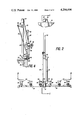
- FIG. 1 shows a side elevation view, partially in section taken on line 1--1 of FIG. 2, of a swing diffuser apparatus according to the invention, as positioned deeply submerged in a waste liquid treatment tank.
- FIG. 2 shows a front elevation view of the invention.
- FIG. 3 shows a plan view of a diffuser array of one type suitable for use in the invention, taken along line 3--3 of FIG. 2.
- FIG. 4 shows a side elevation view, partially in section, of the embodiment of FIG. 1 when the swing diffuser has been raised to its substantially upright position for servicing.
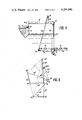
- FIG. 5 shows a side elevation view, partially in section, of another swing diffuser apparatus according to the invention, as positioned shallowly submerged in a waste liquid treatment tank.
- FIG. 6 shows schematically the manner in which the arm lengths and locations of the reach arm pivot points can be determined, based on three preselected desired positions for the diffuser array.
- FIG. 7 shows a modification of the embodiment of FIGS. 1-5, in which the upper reach arm pivot is offset to the opposite side of the upper hanger arm.
- FIG. 8 shows another modification of the embodiment of FIG. 1, in which the diffuser array is asymmetrical about its pivot to the lower hanger arm.
- FIGS. 1 to 4 a portion of a wall 10 and the bottom 12 are illustrated fragmentally for a typical waste liquid treatment tank of the type in which the present invention is used.
- the upper end of wall 10 diverges into a conventional Y-shaped cross section within which headers for compressed air, not shown, are located.
- a grating 14 spans the top of the Y-wall to form a walkway 15 from which the treatment equipment can be serviced and observed.
- the coping 16 adjacent the walkway provides a convenient location for mounting the swing diffuser according to the invention.
- a hollow swing elbow 18 is pivotably mounted to a hollow stanchion or outlet 20 of conventional design, so that elbow 18 can pivot about stanchion 20 in an essentially vertical plane.
- a rigid tubular upper hanger arm 22 is attached to elbow 18 so that arm 22 extends downwardly into the treatment tank, as illustrated.
- a conventional hollow knee joint 24 pivotably connects arm 22 to a rigid tubular lower hanger arm 26 so that a major portion or all of lower arm 26 can be folded toward upper arm 22 and the two arms rotated upwardly to a collapsed position above coping 16, as shown in FIG. 4. All components are made from corrosion resistant material.
- the swing diffuser corresponds to prior art swing diffusers of the type previously mentioned.
- rigid, hollow arms are preferred both to carry the oxidative gas and to support the diffuser array, flexible tubing supported by rigid arms may also be used in the invention.
- a hollow swing elbow 30 is provided which is pivotably mounted to a hollow header connector 32, so that upper hanger arm 22 and header connector 32 have their longitudinal axes in a common vertical plane.
- a pair of hollow half-headers 34, 36 are rigidly connected to header connector 32 and extend laterally from the vertical plane of arm 22 and header connector 32.
- half-headers 34, 36 preferably are of equal length.
- a plurality of cross-headers 38 to 48 are mounted on top of half-headers 34, 36 and preferably at right angles thereto.
- An array of diffusers for oxidative gas is defined by a further plurality of individual plate diffuser assemblies 50 extending upwardly from half-headers 34, 36.
- Assemblies 50 preferably comprise diffusers of the type disclosed in U.S. Ser. No. 952,891, filed Oct. 19, 1978 by Lloyd Ewing, David T. Redmon, Paul M. Thayer, Frank L. Schmit and William H. Roche, for Sewage Aeration Systems, now abandoned, and also assigned to the assignee of the present application.
- diffusers of the type disclosed in U.S. Ser. No. 952,891, filed Oct. 19, 1978 by Lloyd Ewing, David T. Redmon, Paul M. Thayer, Frank L. Schmit and William H. Roche, for Sewage Aeration Systems, now abandoned, and also assigned to the assignee of the present application.
- diffusers of the type disclosed in U.S. Ser. No. 952,891 filed Oct. 19, 1978 by Lloyd Ewing, David T. Redmon, Paul M. Thayer, Frank L. Schmit and William H. Roche, for Sewage Aeration Systems, now abandoned, and also assigned to the assignee of the present application.
- other types of diffusers
- arms 22 and 26 are raised to the folded position above coping 16 as shown in FIG. 4.
- a lever arm 52 and reach arm 54 may be used to cause rotational movement of the diffuser array between its operating and servicing positions, during the raising of arms 22 and 26.
- Lever arm 52 is rigidly attached to header connector 32 and extends, in the illustrated embodiment, toward wall 10 of the treatment tank in a plane essentially parallel with the array.
- arm 52 need not be parallel with the array for the swing diffuser to function as indicated; however, the parallel arrangement is preferred due to its compact geometry.
- arm 52 may comprise one of cross-headers 42, 44, suitably strengthened for the purpose, rather than a separate element as illustrated.
- Reach arm 54 is pivoted at its lower portion to the outer portion 56 of lever arm 52.
- the upper portion 58 of reach arm 54 is pivoted at a point fixed relative to but movable with upper hanger arm 22.
- upper end 58 is pivoted at the end of an offset flange 60 rigidly attached to the lower portion of upper hanger arm 22.
- the diffuser array is movable from the deeply submerged substantially horizontal operating position shown in FIG. 1, through a succession of intermediate positions (not shown in FIGS. 1 to 4) to the substantially upright servicing position shown in FIG. 4.
- the array In the servicing position, the array preferably is oriented substantially upright, substantially at or above the level of the walkway and, as viewed in side elevation, positioned over or adjacent to the edge of walkway 15, so that the individual diffuser assemblies 50 all are readily accessible from walkway 15 without requiring service personnel to reach far out over the treatment tank; yet, hanger arms 22, 26 and reach arms 54 do not block passage on the walkway.
- FIG. 5 illustrates another embodiment of the swing diffuser according to the invention in which the diffuser array is movable from a shallowly submerged substantially horizontal operating position as illustrated, to a substantially upright servicing position, such as shown in FIG. 4.
- the lengths and pivot points of the various arms and levers may require adjustment from those used for the embodiment of FIGS. 1 to 4, in order to provide a shallowly submerged substantially horizontal operating position; or, if desired, one set of arms and pivots can be used to facilitate movement from either the deeply or shallowly submerged operating position to the servicing position.
- FIG. 6 illustrates schematically how the lengths of the various arms and the locations of their pivot points can be determined in accordance with the invention so that the operating position and the servicing position just described for the embodiment of FIGS. 1 to 4 can be achieved.
- the arms are illustrated by single line links and identified by the same reference numbers as in FIGS. 1 to 4, followed by the superscripts 1, 2 and 3 for the operating position, an intermediate position and the servicing position.
- Arm 22 is shown in dashed lines in FIG. 6 and for purposes of determining other link sizes and pivot points, arm 22 is considered to be stationary so that only movement relative to it need be considered.
- lever arm 52 may allow the diffuser array to move to positions not so nearly perpendicular to arm 26, as shown only schematically at position 52 2 . Of course, other intermediate positions may be chosen, as desired. Finally, arm 52 should assume in position 52 3 the orientation required to hold the diffuser array in the essentially vertical position shown in FIG. 4.
- FIGS. 1 to 5 show a swing diffuser in which the diffuser array is arranged symmetrically about the longitudinal axis of upper hanger arm 22. While this arrangement has the advantage that buoyant forces in the operating positions do not develop much of a moment about knee joint 24, it is also within the scope of the invention to use asymmetric diffuser arrays such as shown in FIG. 8. There, the array extends further toward the center of the treatment tank which is desirable in some applications, as will be understood by those skilled in the art. The size and location of the various arms and levers are determined in such an asymmetric embodiment just as for the symmetric embodiment.
- the various components of the swing diffuser according to the present invention will take on differing dimensions depending on the depth of the treatment tank, the depth at which the diffusers are to operate, the type of diffuser used, the desired flow rate for the oxidative gas and related factors.
- upper hanger arm 22 was ten feet long; lower hanger pipe 26, six feet nine inches long; offset flange 60, one foot three inches long and one foot four inches above knee joint 24; lever arm 52, three feet ten inches long; and reach arm 54, nine feet seven inches long.
- This set of lengths provided acceptable stress levels in the various components for a swing diffuser whose normal operating position for the diffuser array was a deeply submerged, essentially horizontal orientation at or near the bottom of the treatment tank, as shown in FIGS. 1 to 4.
- reach arm 54 was shortened to eight feet ten inches and offset flange 60 was lengthened to one foot eleven inches at two feet one-half inch above knee joint 24.
- one set of arm lengths and pivot locations also can be derived to serve both the deeply and shallowly submerged operating positions.
- the invention is intended primarily for use in waste liquid treatment systems of the type used to treat sanitary sewer effluents.
- the swing diffuser apparatus also can be used in other applications where a submerged array of diffusers is required to force a reactive gas through a surrounding liquid medium.
Abstract
Description
Claims (12)
Priority Applications (2)
| Application Number | Priority Date | Filing Date | Title |
|---|---|---|---|
| US06/115,470 US4294696A (en) | 1980-01-25 | 1980-01-25 | Swing diffuser |
| CA000361996A CA1156383A (en) | 1980-01-25 | 1980-10-08 | Swing diffuser |
Applications Claiming Priority (1)
| Application Number | Priority Date | Filing Date | Title |
|---|---|---|---|
| US06/115,470 US4294696A (en) | 1980-01-25 | 1980-01-25 | Swing diffuser |
Publications (1)
| Publication Number | Publication Date |
|---|---|
| US4294696A true US4294696A (en) | 1981-10-13 |
Family
ID=22361616
Family Applications (1)
| Application Number | Title | Priority Date | Filing Date |
|---|---|---|---|
| US06/115,470 Expired - Lifetime US4294696A (en) | 1980-01-25 | 1980-01-25 | Swing diffuser |
Country Status (2)
| Country | Link |
|---|---|
| US (1) | US4294696A (en) |
| CA (1) | CA1156383A (en) |
Cited By (22)
| Publication number | Priority date | Publication date | Assignee | Title |
|---|---|---|---|---|
| EP0068362A1 (en) * | 1981-06-20 | 1983-01-05 | Menzel GmbH. + Co. | Process and apparatus for waste water treatment |
| EP0068363A1 (en) * | 1981-06-20 | 1983-01-05 | Menzel GmbH. + Co. | Process and apparatus for the gasification of a liquid |
| FR2736279A1 (en) * | 1995-07-07 | 1997-01-10 | Kaltchev Roumen | Apparatus for dissolving a gas in a liquid - has gas diffuser immersed in liquid and performing a rapid movement relative to it |
| EP0754087A1 (en) * | 1994-04-05 | 1997-01-22 | Roberts Filter Manufacturing Company | Air grid for underdrain and methods |
| US5804104A (en) * | 1997-03-13 | 1998-09-08 | Meurer Industries, Inc. | Apparatus for moving an aeration unit |
| WO1998040155A1 (en) * | 1997-03-13 | 1998-09-17 | Meurer Industries, Inc. | Method and apparatus for movement of an aeration unit |
| WO1999055628A1 (en) * | 1998-04-29 | 1999-11-04 | Alexandr Teterja | Device for biological wastewater treatment |
| EP1072560A1 (en) * | 1999-07-24 | 2001-01-31 | Arnold Jäger | Apparatus for aerating water with fine air bubbles |
| KR100326209B1 (en) * | 1994-03-11 | 2002-07-27 | 최영기 | Method and apparatus for treating malodor from biological wastewater treatment system employing diffuser and turbo fan |
| US6478964B1 (en) * | 2001-05-18 | 2002-11-12 | Midwest Water Management, Llp | Floating fine-bubble aeration system |
| US6708957B2 (en) | 1998-10-09 | 2004-03-23 | Zenon Environmental Inc. | Moving aerator for immersed membranes |
| US20040201115A1 (en) * | 2003-04-14 | 2004-10-14 | Sebastiani Charles Salvatore | Fluid distribution system and associated methods |
| US20070095737A1 (en) * | 2005-10-31 | 2007-05-03 | Mckinney Jerry L | Aeration vessel and aerator assembly for use in a wastewater treatment system |
| US20070120276A1 (en) * | 2005-11-30 | 2007-05-31 | Siemens Water Technologies Corp. | Hybrid diffuser system headloss balancing |
| US7314572B1 (en) | 2006-02-14 | 2008-01-01 | Meurer Research, Inc. | Methods of and apparatus for low-angle-tray settling with multi-zone configuration |
| US7560035B1 (en) | 2007-06-22 | 2009-07-14 | Charles Lonnie Meurer | Overhead trough with constant trough flow velocity configuration and methods of regulating trough flow velocity |
| US7718076B1 (en) | 2006-02-14 | 2010-05-18 | Charles Lonnie Meurer | Methods of and common gantry drive for single-pass cleaning of multiple stages of a material separation and removal system |
| JP2010158626A (en) * | 2009-01-08 | 2010-07-22 | Sumitomo Heavy Industries Environment Co Ltd | Air diffuser |
| US20100181263A1 (en) * | 2007-07-18 | 2010-07-22 | Bioworks Verfahrenstechnik Gmbh | Method for stirring and/or aerating fluids, particularly sewage, particularly using a floodable aerator |
| US7780015B1 (en) | 2006-08-24 | 2010-08-24 | Meurer Research, Inc. | Methods of and sludge collector with adjacent opposed oppositely-moving blades for moving sludge in a basin |
| US20130113125A1 (en) * | 2010-07-15 | 2013-05-09 | Korea Institute Of Machinery & Materials | Rotating unit-based micro-sized bubble generator |
| USD1015481S1 (en) | 2022-01-06 | 2024-02-20 | Wholesale Septic Supplies, LLC | Articulating diffuser |
Citations (17)
| Publication number | Priority date | Publication date | Assignee | Title |
|---|---|---|---|---|
| US2144385A (en) * | 1935-03-18 | 1939-01-17 | Advance Engineering Company | Sewage treatment apparatus |
| US2221346A (en) * | 1938-07-13 | 1940-11-12 | Chicago Pump Co | Air diffusing means |
| US2328655A (en) * | 1942-02-02 | 1943-09-07 | Chicago Pump Co | Sewage treatment system |
| US2650810A (en) * | 1947-02-26 | 1953-09-01 | Carl H Nordell | Means for raising and lowering diffuser tubes |
| US2815943A (en) * | 1951-01-16 | 1957-12-10 | Chicago Pump Co | Diffuser tube |
| US2997284A (en) * | 1957-07-16 | 1961-08-22 | Fmc Corp | Swing diffuser |
| FR1271718A (en) * | 1960-08-06 | 1961-09-15 | Assembly of diffuser elements for water purification | |
| US3008492A (en) * | 1957-05-24 | 1961-11-14 | Fmc Corp | Quick acting valve |
| US3116021A (en) * | 1962-11-15 | 1963-12-31 | American Well Works | Diffuser swing mechanism |
| US3160685A (en) * | 1961-04-14 | 1964-12-08 | Fmc Corp | Swing diffuser |
| US3339901A (en) * | 1963-03-29 | 1967-09-05 | Chicago Bridge & Iron Co | Aeration equipment with easy-raising facilities |
| NL6709487A (en) * | 1966-07-09 | 1968-01-10 | ||
| US3864441A (en) * | 1973-05-17 | 1975-02-04 | Niigata Engineering Co Ltd | Diffused aeration pipe apparatus for use with an aeration tank |
| US3989627A (en) * | 1975-09-30 | 1976-11-02 | Envirex Inc. | Removable gas diffuser and apparatus therefor |
| JPS5264155A (en) * | 1975-11-25 | 1977-05-27 | Kurita Water Ind Ltd | Air diffuser for air exposure tank |
| US4048267A (en) * | 1972-01-13 | 1977-09-13 | Chicago Bridge & Iron Company | Aeration system with foldable low-loss downcomers and method of operation thereof |
| DE2838204B1 (en) * | 1978-09-01 | 1979-12-06 | Botho Prof. Dr.-Ing. Boehnke | Device for introducing oxygen-containing gases into aeration basins |
-
1980
- 1980-01-25 US US06/115,470 patent/US4294696A/en not_active Expired - Lifetime
- 1980-10-08 CA CA000361996A patent/CA1156383A/en not_active Expired
Patent Citations (18)
| Publication number | Priority date | Publication date | Assignee | Title |
|---|---|---|---|---|
| US2144385A (en) * | 1935-03-18 | 1939-01-17 | Advance Engineering Company | Sewage treatment apparatus |
| US2221346A (en) * | 1938-07-13 | 1940-11-12 | Chicago Pump Co | Air diffusing means |
| US2328655A (en) * | 1942-02-02 | 1943-09-07 | Chicago Pump Co | Sewage treatment system |
| US2650810A (en) * | 1947-02-26 | 1953-09-01 | Carl H Nordell | Means for raising and lowering diffuser tubes |
| US2815943A (en) * | 1951-01-16 | 1957-12-10 | Chicago Pump Co | Diffuser tube |
| US3008492A (en) * | 1957-05-24 | 1961-11-14 | Fmc Corp | Quick acting valve |
| US2997284A (en) * | 1957-07-16 | 1961-08-22 | Fmc Corp | Swing diffuser |
| FR1271718A (en) * | 1960-08-06 | 1961-09-15 | Assembly of diffuser elements for water purification | |
| US3174733A (en) * | 1961-04-14 | 1965-03-23 | Fmc Corp | Swing diffuser |
| US3160685A (en) * | 1961-04-14 | 1964-12-08 | Fmc Corp | Swing diffuser |
| US3116021A (en) * | 1962-11-15 | 1963-12-31 | American Well Works | Diffuser swing mechanism |
| US3339901A (en) * | 1963-03-29 | 1967-09-05 | Chicago Bridge & Iron Co | Aeration equipment with easy-raising facilities |
| NL6709487A (en) * | 1966-07-09 | 1968-01-10 | ||
| US4048267A (en) * | 1972-01-13 | 1977-09-13 | Chicago Bridge & Iron Company | Aeration system with foldable low-loss downcomers and method of operation thereof |
| US3864441A (en) * | 1973-05-17 | 1975-02-04 | Niigata Engineering Co Ltd | Diffused aeration pipe apparatus for use with an aeration tank |
| US3989627A (en) * | 1975-09-30 | 1976-11-02 | Envirex Inc. | Removable gas diffuser and apparatus therefor |
| JPS5264155A (en) * | 1975-11-25 | 1977-05-27 | Kurita Water Ind Ltd | Air diffuser for air exposure tank |
| DE2838204B1 (en) * | 1978-09-01 | 1979-12-06 | Botho Prof. Dr.-Ing. Boehnke | Device for introducing oxygen-containing gases into aeration basins |
Non-Patent Citations (1)
| Title |
|---|
| "Chicago" Swing Diffuser, Chicago Pump Co., Bulletin 175, 20 pages, 7/1938. * |
Cited By (32)
| Publication number | Priority date | Publication date | Assignee | Title |
|---|---|---|---|---|
| EP0068362A1 (en) * | 1981-06-20 | 1983-01-05 | Menzel GmbH. + Co. | Process and apparatus for waste water treatment |
| EP0068363A1 (en) * | 1981-06-20 | 1983-01-05 | Menzel GmbH. + Co. | Process and apparatus for the gasification of a liquid |
| WO1983000040A1 (en) * | 1981-06-20 | 1983-01-06 | Zink, Jürgen | Method and device for mixing a gas to a liquid |
| WO1983000039A1 (en) * | 1981-06-20 | 1983-01-06 | Zink, Jürgen | Method and device for the treatment of waste waters |
| KR100326209B1 (en) * | 1994-03-11 | 2002-07-27 | 최영기 | Method and apparatus for treating malodor from biological wastewater treatment system employing diffuser and turbo fan |
| EP0754087A1 (en) * | 1994-04-05 | 1997-01-22 | Roberts Filter Manufacturing Company | Air grid for underdrain and methods |
| EP0754087A4 (en) * | 1994-04-05 | 1998-06-10 | Roberts Filter Mfg | Air grid for underdrain and methods |
| FR2736279A1 (en) * | 1995-07-07 | 1997-01-10 | Kaltchev Roumen | Apparatus for dissolving a gas in a liquid - has gas diffuser immersed in liquid and performing a rapid movement relative to it |
| WO1998040155A1 (en) * | 1997-03-13 | 1998-09-17 | Meurer Industries, Inc. | Method and apparatus for movement of an aeration unit |
| US5804104A (en) * | 1997-03-13 | 1998-09-08 | Meurer Industries, Inc. | Apparatus for moving an aeration unit |
| WO1999055628A1 (en) * | 1998-04-29 | 1999-11-04 | Alexandr Teterja | Device for biological wastewater treatment |
| US6708957B2 (en) | 1998-10-09 | 2004-03-23 | Zenon Environmental Inc. | Moving aerator for immersed membranes |
| EP1072560A1 (en) * | 1999-07-24 | 2001-01-31 | Arnold Jäger | Apparatus for aerating water with fine air bubbles |
| US6478964B1 (en) * | 2001-05-18 | 2002-11-12 | Midwest Water Management, Llp | Floating fine-bubble aeration system |
| US20040201115A1 (en) * | 2003-04-14 | 2004-10-14 | Sebastiani Charles Salvatore | Fluid distribution system and associated methods |
| US7014176B2 (en) | 2003-04-14 | 2006-03-21 | Rf Delaware, Inc. | Fluid distribution system and associated methods |
| US20070095737A1 (en) * | 2005-10-31 | 2007-05-03 | Mckinney Jerry L | Aeration vessel and aerator assembly for use in a wastewater treatment system |
| US7513994B2 (en) * | 2005-10-31 | 2009-04-07 | Jerry L. Mckinney 2002 Trust | Aeration vessel and aerator assembly for use in a wastewater treatment system |
| US7862014B2 (en) * | 2005-11-30 | 2011-01-04 | Siemens Water Technologies Corp. | Hybrid diffuser system headloss balancing |
| US20070120276A1 (en) * | 2005-11-30 | 2007-05-31 | Siemens Water Technologies Corp. | Hybrid diffuser system headloss balancing |
| US7314572B1 (en) | 2006-02-14 | 2008-01-01 | Meurer Research, Inc. | Methods of and apparatus for low-angle-tray settling with multi-zone configuration |
| US7718076B1 (en) | 2006-02-14 | 2010-05-18 | Charles Lonnie Meurer | Methods of and common gantry drive for single-pass cleaning of multiple stages of a material separation and removal system |
| US8074810B2 (en) | 2006-08-24 | 2011-12-13 | Meurer Research, Inc. | Methods of and sludge collector with adjacent opposed oppositely-moving blades for moving sludge in a basin |
| US7981302B2 (en) | 2006-08-24 | 2011-07-19 | Meurer Research Inc. | Method and apparatus for enhanced settling and collection of settled material |
| US7780015B1 (en) | 2006-08-24 | 2010-08-24 | Meurer Research, Inc. | Methods of and sludge collector with adjacent opposed oppositely-moving blades for moving sludge in a basin |
| US7560035B1 (en) | 2007-06-22 | 2009-07-14 | Charles Lonnie Meurer | Overhead trough with constant trough flow velocity configuration and methods of regulating trough flow velocity |
| US20100181263A1 (en) * | 2007-07-18 | 2010-07-22 | Bioworks Verfahrenstechnik Gmbh | Method for stirring and/or aerating fluids, particularly sewage, particularly using a floodable aerator |
| US8241497B2 (en) * | 2007-07-18 | 2012-08-14 | Bioworks Verfahrenstechnik Gmbh | Method for stirring and/or aerating fluids, particularly sewage, particularly using a floodable aerator |
| JP2010158626A (en) * | 2009-01-08 | 2010-07-22 | Sumitomo Heavy Industries Environment Co Ltd | Air diffuser |
| US20130113125A1 (en) * | 2010-07-15 | 2013-05-09 | Korea Institute Of Machinery & Materials | Rotating unit-based micro-sized bubble generator |
| US9061255B2 (en) * | 2010-07-15 | 2015-06-23 | Korea Institute Of Machinery & Materials | Rotating unit-based micro-sized bubble generator |
| USD1015481S1 (en) | 2022-01-06 | 2024-02-20 | Wholesale Septic Supplies, LLC | Articulating diffuser |
Also Published As
| Publication number | Publication date |
|---|---|
| CA1156383A (en) | 1983-11-01 |
Similar Documents
| Publication | Publication Date | Title |
|---|---|---|
| US4294696A (en) | Swing diffuser | |
| US8246018B2 (en) | Diffuser assembly with buoyancy vessel | |
| JPH0316520B2 (en) | ||
| US4511470A (en) | Apparatus for the recovery of oils or other similar substances floating on streaming water courses | |
| PT854837E (en) | FILLING OF DEPOSITS | |
| US4252162A (en) | Articulated loading arm attitude control system | |
| US3641779A (en) | Stinger system for guiding a pipeline from or on a moving vessel | |
| US3989627A (en) | Removable gas diffuser and apparatus therefor | |
| US3738628A (en) | Removable deep tank gas diffusing apparatus | |
| JPS6139237B2 (en) | ||
| US3236259A (en) | Counterbalanced loading device | |
| US6640828B2 (en) | Flushing apparatus and method thereof | |
| CA1132520A (en) | Adjustable support for underwater pipes at a short distance from the sea bed | |
| EP0024187B1 (en) | System for collecting products dumped on the surface of a mass of water | |
| CN211236701U (en) | Desalted water level control device | |
| US4025976A (en) | Submarine pivoting structure with ducting | |
| JP3993705B2 (en) | Pollution prevention device | |
| SU1437356A1 (en) | Apparatus for biological treatment of waste water | |
| JP3539750B2 (en) | Floating bridge | |
| SU993214A1 (en) | Liquid level regulator | |
| SU1001021A1 (en) | Level control in water-development works pools | |
| SU1418398A2 (en) | Apparatus for producing waves in open water flow | |
| KR820002274B1 (en) | Floating roof drainage system | |
| SU972182A2 (en) | Automatic device for feeding liquid from one tank to another | |
| SU971822A1 (en) | Arrangement for lifting section of pneumatic aerators |
Legal Events
| Date | Code | Title | Description |
|---|---|---|---|
| STCF | Information on status: patent grant |
Free format text: PATENTED CASE |
|
| AS | Assignment |
Owner name: NORWEST BANK ST. PAUL, NATIONAL ASSOCIATION Free format text: SECURITY INTEREST;ASSIGNOR:WATER POLLUTION CONTROL CORP.;REEL/FRAME:004600/0002 Effective date: 19860730 Owner name: NORWEST BANK ST. PAUL, NATIONAL ASSOCIATION,STATEL Free format text: SECURITY INTEREST;ASSIGNOR:WATER POLLUTION CONTROL CORP.;REEL/FRAME:004600/0002 Effective date: 19860730 |
|
| AS | Assignment |
Owner name: WATER POLLUTION CONTROL CORP., A CORP. OF DE. Free format text: MERGER;ASSIGNOR:WATER POLLUTION CONTROL CORP., A WI CORP;REEL/FRAME:004652/0469 Effective date: 19860811 Owner name: WATER POLLUTION CONTROL CORP. Free format text: MERGER;ASSIGNOR:WATER POLLUTION CONTROL CORP., A WI CORP;REEL/FRAME:004652/0469 Effective date: 19860811 |
|
| AS | Assignment |
Owner name: WATER POLLUTION CONTROL CORP. Free format text: MERGER;ASSIGNOR:SANITAIRE ACQUISITION CORP.;REEL/FRAME:004690/0409 Effective date: 19870317 |
|
| AS | Assignment |
Owner name: FIRST WISCONSIN NATIONAL BANK OF MILWAUKEE, 777 EA Free format text: SECURITY INTEREST;ASSIGNOR:WATER POLLUTION CONTROL CORP. A CORP. OF WI;REEL/FRAME:004757/0741 Effective date: 19870902 |
|
| AS | Assignment |
Owner name: WATER POLLUTION CONTROL CORP. Free format text: RELEASED BY SECURED PARTY;ASSIGNOR:FIRST WISCONSIN NATIONAL BANK OF MILWAUKEE;REEL/FRAME:005612/0020 Effective date: 19901213 |
|
| AS | Assignment |
Owner name: WATER POLLUTION CONTROL CORP., WISCONSIN Free format text: RELEASE BY SECURED PARTY;ASSIGNOR:NORWEST BANK ST. PAUL, NATIONAL ASSOCIATION N/K/A NORWEST BANK MINNESOTA, NATIONAL ASSOCIATION;REEL/FRAME:007108/0384 Effective date: 19940630 |
|
| AS | Assignment |
Owner name: ITT MANUFACTURING ENTERPRISES, INC., DELAWARE Free format text: INVALID ASSIGNMENT.;ASSIGNOR:SANITAIRE CORPORATION;REEL/FRAME:011511/0778 Effective date: 20001221 Owner name: SANITAIRE ACQUISITION CORP., DELAWARE Free format text: CERTIFICATE OF OWNERSHIP AND MERGER;ASSIGNOR:WATER POLLUTION CONTROL CORP.;REEL/FRAME:011511/0897 Effective date: 19860811 Owner name: SANITAIRE CORPORATION, WISCONSIN Free format text: CHANGE OF NAME;ASSIGNOR:WATER POLLUTION CONTROL CORP.;REEL/FRAME:011533/0317 Effective date: 19990429 Owner name: ITT MANUFACTURING ENTERPRISES, INC., DELAWARE Free format text: ASSIGNMENT OF ASSIGNORS INTEREST;ASSIGNOR:SANITAIRE CORPORATION;REEL/FRAME:011541/0101 Effective date: 20001221 |