US4307479A - Angle tufted rotary brush assembly - Google Patents
Angle tufted rotary brush assembly Download PDFInfo
- Publication number
- US4307479A US4307479A US06/086,463 US8646379A US4307479A US 4307479 A US4307479 A US 4307479A US 8646379 A US8646379 A US 8646379A US 4307479 A US4307479 A US 4307479A
- Authority
- US
- United States
- Prior art keywords
- midplane
- roller body
- bristle
- bristles
- brush
- Prior art date
- Legal status (The legal status is an assumption and is not a legal conclusion. Google has not performed a legal analysis and makes no representation as to the accuracy of the status listed.)
- Expired - Lifetime
Links
Images

Classifications
-
- A—HUMAN NECESSITIES
- A47—FURNITURE; DOMESTIC ARTICLES OR APPLIANCES; COFFEE MILLS; SPICE MILLS; SUCTION CLEANERS IN GENERAL
- A47L—DOMESTIC WASHING OR CLEANING; SUCTION CLEANERS IN GENERAL
- A47L9/00—Details or accessories of suction cleaners, e.g. mechanical means for controlling the suction or for effecting pulsating action; Storing devices specially adapted to suction cleaners or parts thereof; Carrying-vehicles specially adapted for suction cleaners
- A47L9/02—Nozzles
- A47L9/04—Nozzles with driven brushes or agitators
- A47L9/0461—Dust-loosening tools, e.g. agitators, brushes
- A47L9/0466—Rotating tools
- A47L9/0477—Rolls
-
- A—HUMAN NECESSITIES
- A46—BRUSHWARE
- A46B—BRUSHES
- A46B7/00—Bristle carriers arranged in the brush body
- A46B7/04—Bristle carriers arranged in the brush body interchangeably removable bristle carriers
-
- A—HUMAN NECESSITIES
- A46—BRUSHWARE
- A46B—BRUSHES
- A46B9/00—Arrangements of the bristles in the brush body
- A46B9/02—Position or arrangement of bristles in relation to surface of the brush body, e.g. inclined, in rows, in groups
Definitions
- This invention relates to the field of brushes, and more particularly to an improved angled bristle array configuration in a rotary brush assembly of the type used in vacuum cleaners.
- Rotary brush assemblies have included a generally cylindrical brush roller body carrying on its outer surface an array of radially extending tufted bristles.
- the roller body is mounted on the vacuum cleaner for powered sweeping rotation, to loosen debris to facilitate its removal by appropriate air flow.
- Beater bars are sometimes also attached to the roller body to enhance cleaning efficiency.
- the bristle array and beater bars are distributed regularly about the periphery of the roller body to balance the moments of inertia about the roller body axis.
- One form of known rotary brush assembly includes a brush roller having several helical rows of bristle tufts distributed on its periphery.
- the bristles extend outwardly from the brush roller substantially perpendicular to the roller axis.
- alternate rows of bristles about the roller circumference comprise bristles having differing degrees of stiffness. For example, one proposal is to use alternate rows of horse and goat hair.
- Such rotary brush assemblies have exhibited undesirable nonuniformity in sweeping efficiency along the length of the assembly.
- Such assemblies have included the use of somewhat longer bristles for the more angled tufts than in those which are more closely perpendicular to the roller body axis. Such an arrangement provides equal bristle extension from the roller body axis. Residual sweeping nonuniformity remained, because the longer, more angled, bristles were less stiff than the shorter, less angled ones.
- a rotary brush assembly which obviates the foregoing disadvantages of prior structure.
- Such an assembly includes a generally cylindrical brush roller body carrying an array of bristles.
- the bristles are angled, with respect to the roller body axis, in an amount which is a function of the longitudinal bristle location along the roller body. Additionally, the stiffness of the individual bristles is a function of bristle angulation.
- This structure affords the advantages of wider cleaning range and good edge cleaning capabilities associated with bristle angulation, while ameliorating previous nonuniformity of cleaning action along the length of the brush assembly.
- a more specific aspect of the invention involves providing bristles having a diameter which is an increasing function of the degree of angulation of the bristles. This structure results in the more angled bristles having greater stiffness than those of lesser angulation. Hence, the more angled bristles can be longer, without sacrificing uniformity of cleaning action along the roller body length.
- the roller body defines grooves in its external surface, for accomodating portions of brush strip substrate material into which bristle tufts are inserted.
- a single brush strip extending substantially the entire length of a groove from one end of the roller body to the other is provided.
- bristle tufts near the midplane of the roller body are substantially normal to the roller body axis, while tufting near the ends is angled outwardly away form the midplane.
- two portions of brush strip substrate material carrying tufts are laid end to end in each groove.
- tufts near the middle of each separate brush strip substrate portion are normal to the roller body axis, while tufting at each end of each of the substrate portions is angled outwardly.
- a rotary brush assembly including structure adapted for holding an array of bristles of differing length attached to the bristle holding structure.
- the bristles are provided with a stiffness which is an increasing function of bristle length.
- a rotary brush assembly including structure adapted for holding a bristle array and an array of bristles of differing length attached to the bristle holding structure.
- the bristles have a diameter which increases with respect to bristle length.
- Another feature of the invention comprises a rotary brush assembly having a generally cylindrical brush roller body and two brush strip substrate portions placed end to end and attached to the roller body.
- the brush strip substrate portions each carry an array of bristle tufts.
- Locking structure is provided for coupling together adjacent ends of the brush strip substrate portion, to inhibit their longitudinal separation which tends to result from rapid rotation of the rotary brush assembly.
- the locking structure is integrally defined by the adjacent ends of the brush strip portions themselves.
- FIG. 1 is an elevational view of a rotary brush assembly incorporating the present invention
- FIG. 2 is an elevational view, partially broken away, of a portion of the assembly shown in FIG. 1;
- FIG. 3 is a plan view illustrating another portion of the assembly of FIG. 1;
- FIG. 4 is a cross-sectional detailed view of a portion of the structure of FIG. 3 taken along the lines 4--4 of FIG. 3;
- FIG. 5 is another detailed cross-sectional view of a portion of the assembly of FIG. 1, taken along the lines 5--5;
- FIG. 6 is an elevational view of another embodiment of a rotary brush assembly of the present invention.
- FIG. 7 is an elevational view of a portion of the assembly of FIG. 6.
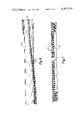
- FIG. 1 illustrates a rotary brush assembly B incorporating the present invention.
- the brush assembly B includes a generally cylindrical roller body 10 having an axis A and carrying an array of bristle tufts, indicated for example at 12, on its external surface.
- the assembly B is suited for incorporation in known fashion into a vacuum cleaner.
- the rotary brush assembly is power rotated at high speed in the vicinity of the swept surface, so that its bristles loosen debris from the surface to facilitate its removal by appropriate air flow generated by the cleaner.
- the roller body defines a set of generally helical grooves 14 in its surface.
- One of the grooves 14 is illustrated in detailed cross-section in FIG. 5.
- the grooves 14 are preferably disposed symmetrically about the outer surface of the roller body 10.
- the bristle tufts 12 are mounted in and comprise parts of brush strip elements, an example of which is illustrated in FIG. 2.
- Each brush strip includes a plurality of bristle tufts 12 inserted into holes, such as 16, drilled into a brush strip substrate portion 18.
- the brush strip substrate portion is preferably made from a durable plastic material, and has a cross-sectional configuration similar to the interior cross-sectional configuration of the groove 14.
- bristle tufts 12 can be mounted on the outer surface of the roller body 10 by inserting the brush strip substrate portions, bearing the bristle tufts, in the respective grooves defined in the roller body surface.
- two brush strips each bearing bristle tufts, are inserted end to end in each roller body surface groove.
- the junction between brush strips is referred to by the reference character 20.
- each bristle tuft is a function of its respective location along the length of the brush strip, as shown in FIG. 2. More specifically, the tufting in the region near the middle of each brush strip is substantially normal to the longitudinal axis of the strip. The angulation of each tuft with respect to the normal is an increasing function of the longitudinal distance of the tuft from the middle of the brush strip. Angulation of bristle tuft increases from zero degrees, with respect to the normal, at the brush strip middle, to approximately thirty degrees outwardly from the normal at each end of the brush strip.
- the bristles of the brush assembly are made of nylon. Bristles angled less than approximately fifteen degrees to the normal have a diameter of approximately 0.006 inches. Bristles angled more than approximately fifteen degrees to the normal are provided with a diameter of approximately 0.008 inches.
- Interlocking structure is provided for longitudinally fastening together adjacent ends of the brush strip substrate portions 18. Referring to FIGS. 3 and 4, the brush strip substrate portions are connected at location 20 by means of locking structure integrally defined by the ends of the brush strip substrate portions themselves.
- the interlocking structure is embodied by mutually mating end configurations including lip and flanged portions 22, 24.
- the interlocking structure inhibits outward migration of the brush strip toward the roller body ends which would otherwise tend to result due to rotation of the brush assembly.
- FIGS. 6 and 7 Another embodiment of a rotary brush assembly is shown in FIGS. 6 and 7.
- the brush strip substrate portion 118 extends the entire length of grooves such as 114 defined in the outer surface of a roller body 110.
- the angulation of the bristle tufts 112 is somewhat different than in the embodiment of FIG. 1.
- the bristle tufts near a midplane are substantially parallel to the midplane and normal to the axis.
- the outward angulation of bristle tufts with respect to the midplane is an increasing function of the longitudinal distance of the tufts from the midplane.
- the end tuft has an angulation of approximately thirty degrees outwardly from the midplane.
Abstract
A rotary brush assembly, suitable for use in a vacuum cleaner, is disclosed. The assembly includes a generally cylindrical brush roller body carrying an array of helical rows of bristle tufts. In one embodiment, bristle tufts near a midplane normal to the roller body axis and equidistant between its ends are substantially normal to the roller body axis. Other bristle tufts are angled away from the midplane in an amount which is an increasing function of their distance from the midplane. Bristle stiffness is an increasing function of the degree of tuft angulation.
In another embodiment, the roller body defines helical grooves in its outer surface, and two brush strip substrate portions bearing the bristle tufts are inserted end to end in each groove. Adjacent brush strip ends define structure for interlocking the brush strips for inhibiting longitudinal separation of the brush strips, which would otherwise tend to result from brush rotation. In this embodiment, bristle tuft angulation from the normal is a function of tuft displacement from the midpoint of each individual substrate portion.
Description
1. Field of the Invention
This invention relates to the field of brushes, and more particularly to an improved angled bristle array configuration in a rotary brush assembly of the type used in vacuum cleaners.
2. Description of the Prior Art
The use of rotary brush assemblies in cleaning apparatus such as vacuum cleaners is well known. Rotary brush assemblies have included a generally cylindrical brush roller body carrying on its outer surface an array of radially extending tufted bristles. The roller body is mounted on the vacuum cleaner for powered sweeping rotation, to loosen debris to facilitate its removal by appropriate air flow. Beater bars are sometimes also attached to the roller body to enhance cleaning efficiency. The bristle array and beater bars are distributed regularly about the periphery of the roller body to balance the moments of inertia about the roller body axis.
An example of a prior art rotary brush assembly is described in U.S. Pat. No. 3,874,017, issued on Apr. 1, 1975 to Russel H. R. Parker, and assigned to the present Assignee. This patent is expressly incorporated by reference here.
One form of known rotary brush assembly includes a brush roller having several helical rows of bristle tufts distributed on its periphery. In such an assembly, the bristles extend outwardly from the brush roller substantially perpendicular to the roller axis. It has been proposed that alternate rows of bristles about the roller circumference comprise bristles having differing degrees of stiffness. For example, one proposal is to use alternate rows of horse and goat hair.
It has also been proposed to drill holes in the outside surface of a wooden cylindrical roller body at differing angles with respect to its axis. Identical bristle tufts were then inserted in the various holes and fastened therein with wire staples or the like. In such an assembly, in order to achieve a wider sweeping range and to improve edge cleaning capability, it has been proposed that the end bristle tufts near the roller body ends be angled outwardly.
Such rotary brush assemblies have exhibited undesirable nonuniformity in sweeping efficiency along the length of the assembly.
Such assemblies have included the use of somewhat longer bristles for the more angled tufts than in those which are more closely perpendicular to the roller body axis. Such an arrangement provides equal bristle extension from the roller body axis. Residual sweeping nonuniformity remained, because the longer, more angled, bristles were less stiff than the shorter, less angled ones.
It is thus an object of this invention to provide a rotary brush assembly having advantages of appropriately angled bristle tufting without disadvantages of nonuniform sweeping action.
A rotary brush assembly is provided which obviates the foregoing disadvantages of prior structure. Such an assembly includes a generally cylindrical brush roller body carrying an array of bristles. The bristles are angled, with respect to the roller body axis, in an amount which is a function of the longitudinal bristle location along the roller body. Additionally, the stiffness of the individual bristles is a function of bristle angulation.
This structure affords the advantages of wider cleaning range and good edge cleaning capabilities associated with bristle angulation, while ameliorating previous nonuniformity of cleaning action along the length of the brush assembly.
A more specific aspect of the invention involves providing bristles having a diameter which is an increasing function of the degree of angulation of the bristles. This structure results in the more angled bristles having greater stiffness than those of lesser angulation. Hence, the more angled bristles can be longer, without sacrificing uniformity of cleaning action along the roller body length.
According to another specific feature, the roller body defines grooves in its external surface, for accomodating portions of brush strip substrate material into which bristle tufts are inserted.
In one specific embodiment, a single brush strip extending substantially the entire length of a groove from one end of the roller body to the other is provided. In such an embodiment, bristle tufts near the midplane of the roller body are substantially normal to the roller body axis, while tufting near the ends is angled outwardly away form the midplane.
In a different embodiment, two portions of brush strip substrate material carrying tufts are laid end to end in each groove. In such an embodiment, tufts near the middle of each separate brush strip substrate portion are normal to the roller body axis, while tufting at each end of each of the substrate portions is angled outwardly.
In accordance with another aspect of the invention, there is provided a rotary brush assembly including structure adapted for holding an array of bristles of differing length attached to the bristle holding structure. The bristles are provided with a stiffness which is an increasing function of bristle length.
In accordance with a more specific aspect of the invention, a rotary brush assembly is provided including structure adapted for holding a bristle array and an array of bristles of differing length attached to the bristle holding structure. The bristles have a diameter which increases with respect to bristle length.
Another feature of the invention comprises a rotary brush assembly having a generally cylindrical brush roller body and two brush strip substrate portions placed end to end and attached to the roller body. As previously described, the brush strip substrate portions each carry an array of bristle tufts. Locking structure is provided for coupling together adjacent ends of the brush strip substrate portion, to inhibit their longitudinal separation which tends to result from rapid rotation of the rotary brush assembly.
In accordance with a more specific feature, the locking structure is integrally defined by the adjacent ends of the brush strip portions themselves.
This invention will be understood in more detail by reference to the following detailed description, and to the drawings, in which:
FIG. 1 is an elevational view of a rotary brush assembly incorporating the present invention;
FIG. 2 is an elevational view, partially broken away, of a portion of the assembly shown in FIG. 1;
FIG. 3 is a plan view illustrating another portion of the assembly of FIG. 1;
FIG. 4 is a cross-sectional detailed view of a portion of the structure of FIG. 3 taken along the lines 4--4 of FIG. 3;
FIG. 5 is another detailed cross-sectional view of a portion of the assembly of FIG. 1, taken along the lines 5--5;
FIG. 6 is an elevational view of another embodiment of a rotary brush assembly of the present invention;
FIG. 7 is an elevational view of a portion of the assembly of FIG. 6.
FIG. 1 illustrates a rotary brush assembly B incorporating the present invention. The brush assembly B includes a generally cylindrical roller body 10 having an axis A and carrying an array of bristle tufts, indicated for example at 12, on its external surface. The assembly B is suited for incorporation in known fashion into a vacuum cleaner. In such an application, the rotary brush assembly is power rotated at high speed in the vicinity of the swept surface, so that its bristles loosen debris from the surface to facilitate its removal by appropriate air flow generated by the cleaner.
In the embodiment of FIG. 1, the roller body defines a set of generally helical grooves 14 in its surface. One of the grooves 14 is illustrated in detailed cross-section in FIG. 5. The grooves 14 are preferably disposed symmetrically about the outer surface of the roller body 10.
The bristle tufts 12 are mounted in and comprise parts of brush strip elements, an example of which is illustrated in FIG. 2. Each brush strip includes a plurality of bristle tufts 12 inserted into holes, such as 16, drilled into a brush strip substrate portion 18. The brush strip substrate portion is preferably made from a durable plastic material, and has a cross-sectional configuration similar to the interior cross-sectional configuration of the groove 14.
Thus, bristle tufts 12 can be mounted on the outer surface of the roller body 10 by inserting the brush strip substrate portions, bearing the bristle tufts, in the respective grooves defined in the roller body surface.
Preferably, and as illustrated in FIG. 1, two brush strips, each bearing bristle tufts, are inserted end to end in each roller body surface groove. In FIG. 1, the junction between brush strips is referred to by the reference character 20.
The angulation of each bristle tuft is a function of its respective location along the length of the brush strip, as shown in FIG. 2. More specifically, the tufting in the region near the middle of each brush strip is substantially normal to the longitudinal axis of the strip. The angulation of each tuft with respect to the normal is an increasing function of the longitudinal distance of the tuft from the middle of the brush strip. Angulation of bristle tuft increases from zero degrees, with respect to the normal, at the brush strip middle, to approximately thirty degrees outwardly from the normal at each end of the brush strip.
Longer bristles are provided for tufts more outwardly angled than for those tufts less angled. Bristle length increases with respect to increasing angulation in order that all the bristles extend a substantially equal distance transverse from the brush strip substrate material, and consequently from the axis A of the roller body 10. This feature tends to enhance uniformity of cleaning performance of the rotating brush assembly along its entire axial length.
The more angled, and hence longer, bristle tufts are provided with stiffer bristles than are the less angled and shorter tufts. In a specific embodiment, the bristles of the brush assembly are made of nylon. Bristles angled less than approximately fifteen degrees to the normal have a diameter of approximately 0.006 inches. Bristles angled more than approximately fifteen degrees to the normal are provided with a diameter of approximately 0.008 inches.
This additional stiffness for the longer bristles further enhances uniformity of the vigor of the sweeping action along the length of the brush assembly.
Interlocking structure is provided for longitudinally fastening together adjacent ends of the brush strip substrate portions 18. Referring to FIGS. 3 and 4, the brush strip substrate portions are connected at location 20 by means of locking structure integrally defined by the ends of the brush strip substrate portions themselves.
More specifically, and as shown in FIG. 4, the interlocking structure is embodied by mutually mating end configurations including lip and flanged portions 22, 24. The interlocking structure inhibits outward migration of the brush strip toward the roller body ends which would otherwise tend to result due to rotation of the brush assembly.
Another embodiment of a rotary brush assembly is shown in FIGS. 6 and 7. In such an embodiment, the brush strip substrate portion 118 extends the entire length of grooves such as 114 defined in the outer surface of a roller body 110. Obviously, where only a single brush strip portion is utilized in a groove, there is no need for providing the interlocking structure of FIGS. 3 and 4. Moreover, the angulation of the bristle tufts 112 is somewhat different than in the embodiment of FIG. 1.
More specifically, in the FIG. 6 and 7 embodiment, the bristle tufts near a midplane, equally distant between the roller body ends and normal to its axes, are substantially parallel to the midplane and normal to the axis. The outward angulation of bristle tufts with respect to the midplane is an increasing function of the longitudinal distance of the tufts from the midplane. As in the embodiment of FIG. 1, the end tuft has an angulation of approximately thirty degrees outwardly from the midplane.
It is to be understood that the present disclosure is illustrative of the invention, rather than exhaustive. Those of ordinary skill may make additions, deletions or modifications to the disclosed structure without departing from the spirit of the invention, or its scope, as defined in the appended claims:
Claims (4)
1. A rotary brush assembly comprising:
(a) a generally cylindrical brush roller body having at least one longitudinally extending helical groove defined in its outer surface;
(b) two brush strip substrate portions mounted end to end in each said groove and defining locking structure for coupling together, against relative longitudinal movement, adjacent ends of the substrate portions approximately equidistant the ends of the cylindrical roller body;
(c) a tufted array of bristles mounted on each brush strip substrate portion, said bristles:
(i) having an angle, with respect to a midplane normal to the roller body axis and equidistant its ends, which angle is an increasing function of bristle spacing from said midplane, the angulation of said bristles ranging from approximately parallel to the midplane near the midplane to approximately 30 degrees outwardly from the midplane at the ends of the roller body;
(ii) having a length which is an increasing function of bristle angulation from said midplane, and
(iii) having a stiffness which is an increasing function of said bristle angulation.
2. The rotary brush assembly of claim 1, wherein:
(a) said bristles having an angle of less than approximately 15 degrees with respect to said midplane are of a first diameter, and
(b) said bristles having an angle of more than approximately 15 degrees to the midplane have a second diameter greater than said first diameter.
3. A rotary brush assembly comprising:
(a) a generally cylindrical roller body;
(b) an array of bristles carried on the roller body, said bristles:
(i) being angled with respect to the roller body axis in an amount which is an increasing function of bristle distance from the midplane of the roller body;
(ii) having a stiffness which is an increasing function of said bristle angle, and
(iii) the diameter of said bristle increasing with respect to increasing bristle angle relative to the midplane normal to the roller body axis.
4. A rotary brush assembly comprising:
(a) a generally cylindrical brush roller body defining a midplane located equal distance between the roller body ends;
(b) an array of nylon bristles carried on the roller body, said bristles:
(i) having an angle to said midplane ranging from approximately parallel to said midplane near said midplane to about 30° outwardly from the midplane at the ends of the roller body;
(ii) being angled less than about 15° from the midplane having a diameter of about 0.006 inches, and
(iii) being angled more than about 15° to the midplane having a diameter of about 0.008 inches.
Priority Applications (1)
| Application Number | Priority Date | Filing Date | Title |
|---|---|---|---|
| US06/086,463 US4307479A (en) | 1979-10-19 | 1979-10-19 | Angle tufted rotary brush assembly |
Applications Claiming Priority (1)
| Application Number | Priority Date | Filing Date | Title |
|---|---|---|---|
| US06/086,463 US4307479A (en) | 1979-10-19 | 1979-10-19 | Angle tufted rotary brush assembly |
Publications (1)
| Publication Number | Publication Date |
|---|---|
| US4307479A true US4307479A (en) | 1981-12-29 |
Family
ID=22198732
Family Applications (1)
| Application Number | Title | Priority Date | Filing Date |
|---|---|---|---|
| US06/086,463 Expired - Lifetime US4307479A (en) | 1979-10-19 | 1979-10-19 | Angle tufted rotary brush assembly |
Country Status (1)
| Country | Link |
|---|---|
| US (1) | US4307479A (en) |
Cited By (34)
| Publication number | Priority date | Publication date | Assignee | Title |
|---|---|---|---|---|
| US4372004A (en) * | 1981-04-03 | 1983-02-08 | The Singer Company | Wide-sweep carpet cleaner bristle strip and brush roll |
| WO1985002522A1 (en) * | 1983-12-12 | 1985-06-20 | Campbell's Janitor Supplies Pty. Ltd. | Improved floor maintenance brush |
| FR2614188A1 (en) * | 1987-04-27 | 1988-10-28 | Rozier Henry | Cleaning brush, particularly for a vehicle such as a road sweeper |
| US5083840A (en) * | 1988-04-27 | 1992-01-28 | Minnesota Mining And Manufacturing Company | Method of preparing an industrial cylinder brush arrangement for operation |
| US5295894A (en) * | 1991-09-24 | 1994-03-22 | Ludo De Cleroq | Device for removing lids from honeycombs |
| US6574823B1 (en) * | 2001-02-12 | 2003-06-10 | The Scott Fetzer Company | Brushroll |
| US6591441B2 (en) * | 2001-10-10 | 2003-07-15 | The Scott Fetzer Company | Brushroll having improved cleaning capability |
| US20030145424A1 (en) * | 2002-02-01 | 2003-08-07 | Royal Appliance Mfg. Co. | Two-piece brushroll |
| US6760952B1 (en) | 2003-06-20 | 2004-07-13 | The Scott Fetzer Company | Vacuum cleaner brushroll |
| US20040185762A1 (en) * | 2003-03-17 | 2004-09-23 | Turch Steven E. | Abrasive brush elements and segments |
| US20050039282A1 (en) * | 2003-08-22 | 2005-02-24 | Oreck Holdings, Llc | Vacuum cleaner brushroll |
| US20060053584A1 (en) * | 2004-09-16 | 2006-03-16 | Panasonic Corporation Of North America | Rotary agitator with reverse helix pattern |
| US20060282964A1 (en) * | 2005-05-13 | 2006-12-21 | Sclafani Adam C | Motorized broom and collector |
| GB2482227A (en) * | 2010-07-22 | 2012-01-25 | Panasonic Corp North America | Rotary agitator |
| CN103932635A (en) * | 2013-01-17 | 2014-07-23 | 戴森技术有限公司 | Agitator for a surface treating appliance |
| GB2518882A (en) * | 2013-10-04 | 2015-04-08 | Richard William Renwick | 3 axis cylinder brush |
| USD747052S1 (en) * | 2013-10-18 | 2016-01-05 | Irobot Corporation | Vacuum roller |
| USD781594S1 (en) * | 2014-12-30 | 2017-03-21 | Maschinenfabrik Huete GmbH & Co. KG | Cleaning brush |
| USD781595S1 (en) * | 2014-12-30 | 2017-03-21 | Maschinenfabrik Huete GmbH & Co. KG | Cleaning brush |
| US9693663B2 (en) | 2013-03-15 | 2017-07-04 | Bissell Homecare, Inc. | Tufting method and brushroll for vacuum cleaner |
| US9756998B2 (en) | 2014-05-28 | 2017-09-12 | Bissell Homecare, Inc. | Brushroll for vacuum cleaner |
| DE202018101345U1 (en) | 2018-03-09 | 2018-04-06 | Lee Fook Yuen | Brush with molded brush strips |
| USD840695S1 (en) * | 2017-01-26 | 2019-02-19 | Tsuchiya Tsco Co., Ltd. | Brush material |
| EP1806990B1 (en) * | 2004-09-28 | 2019-07-10 | Andrea Dondi | Tool for cleaning surfaces |
| USD855333S1 (en) | 2017-01-26 | 2019-08-06 | Tsuchiya Tsco Co., Ltd. | Brush roller |
| USD856000S1 (en) * | 2017-01-26 | 2019-08-13 | Tsuchiya Tsco Co., Ltd. | Brush material |
| USD856001S1 (en) * | 2017-01-26 | 2019-08-13 | Tsuchiya Tsco Co., Ltd. | Brush material |
| US10905297B2 (en) | 2018-01-05 | 2021-02-02 | Irobot Corporation | Cleaning head including cleaning rollers for cleaning robots |
| US11109727B2 (en) | 2019-02-28 | 2021-09-07 | Irobot Corporation | Cleaning rollers for cleaning robots |
| US20220079402A1 (en) * | 2019-06-03 | 2022-03-17 | Dyson Technology Limited | Cleaner head for a vacuum cleaner |
| US20220347895A1 (en) * | 2019-06-07 | 2022-11-03 | Ipco Germany Gmbh | Spreader roll for a distributing device |
| US11638507B2 (en) | 2018-10-04 | 2023-05-02 | Techtronic Cordless Gp | Vacuum cleaner |
| US11826009B2 (en) | 2017-12-12 | 2023-11-28 | Dyson Technology Limited | Cleaner head for a vacuum cleaner |
| WO2023227990A1 (en) * | 2022-05-24 | 2023-11-30 | Dyson Technology Limited | Agitator element for a vacuum cleaner |
Citations (12)
| Publication number | Priority date | Publication date | Assignee | Title |
|---|---|---|---|---|
| US1005801A (en) * | 1907-01-28 | 1911-10-17 | American Finishing Machinery Company | Cloth-stretching machine. |
| GB495982A (en) * | 1937-06-25 | 1938-11-23 | Walter Wessel Junior | Improvements in or relating to brushes or pads |
| US2740985A (en) * | 1949-11-10 | 1956-04-10 | Hoover Co | Agitator structure for cleaning devices |
| US2753583A (en) * | 1951-02-15 | 1956-07-10 | Sunbeam Corp | Grooming device |
| US3533125A (en) * | 1968-08-21 | 1970-10-13 | James A Buechel | Segmental cylindrical brush assembly |
| US3588937A (en) * | 1968-12-05 | 1971-06-29 | Ind Brush Co | Street sweeping broom construction with inclined bristles |
| US3683444A (en) * | 1971-03-29 | 1972-08-15 | Nat Union Electric Corp | Suction cleaner brush roll assembly |
| US3742549A (en) * | 1972-02-03 | 1973-07-03 | I Scopp | Contoured toothbrush |
| US3758915A (en) * | 1971-09-13 | 1973-09-18 | Swanson Electric Shop | Roller for combing shag rugs |
| US3874017A (en) * | 1973-07-18 | 1975-04-01 | Superior Brush Co | Rotary brush assembly |
| SU677744A1 (en) * | 1978-02-06 | 1979-08-05 | Sadykov Zharylkasyn S | Brush |
| US4173807A (en) * | 1977-06-29 | 1979-11-13 | Dupro Ag | Cleaning implement |
-
1979
- 1979-10-19 US US06/086,463 patent/US4307479A/en not_active Expired - Lifetime
Patent Citations (12)
| Publication number | Priority date | Publication date | Assignee | Title |
|---|---|---|---|---|
| US1005801A (en) * | 1907-01-28 | 1911-10-17 | American Finishing Machinery Company | Cloth-stretching machine. |
| GB495982A (en) * | 1937-06-25 | 1938-11-23 | Walter Wessel Junior | Improvements in or relating to brushes or pads |
| US2740985A (en) * | 1949-11-10 | 1956-04-10 | Hoover Co | Agitator structure for cleaning devices |
| US2753583A (en) * | 1951-02-15 | 1956-07-10 | Sunbeam Corp | Grooming device |
| US3533125A (en) * | 1968-08-21 | 1970-10-13 | James A Buechel | Segmental cylindrical brush assembly |
| US3588937A (en) * | 1968-12-05 | 1971-06-29 | Ind Brush Co | Street sweeping broom construction with inclined bristles |
| US3683444A (en) * | 1971-03-29 | 1972-08-15 | Nat Union Electric Corp | Suction cleaner brush roll assembly |
| US3758915A (en) * | 1971-09-13 | 1973-09-18 | Swanson Electric Shop | Roller for combing shag rugs |
| US3742549A (en) * | 1972-02-03 | 1973-07-03 | I Scopp | Contoured toothbrush |
| US3874017A (en) * | 1973-07-18 | 1975-04-01 | Superior Brush Co | Rotary brush assembly |
| US4173807A (en) * | 1977-06-29 | 1979-11-13 | Dupro Ag | Cleaning implement |
| SU677744A1 (en) * | 1978-02-06 | 1979-08-05 | Sadykov Zharylkasyn S | Brush |
Cited By (48)
| Publication number | Priority date | Publication date | Assignee | Title |
|---|---|---|---|---|
| US4372004A (en) * | 1981-04-03 | 1983-02-08 | The Singer Company | Wide-sweep carpet cleaner bristle strip and brush roll |
| WO1985002522A1 (en) * | 1983-12-12 | 1985-06-20 | Campbell's Janitor Supplies Pty. Ltd. | Improved floor maintenance brush |
| FR2614188A1 (en) * | 1987-04-27 | 1988-10-28 | Rozier Henry | Cleaning brush, particularly for a vehicle such as a road sweeper |
| US5083840A (en) * | 1988-04-27 | 1992-01-28 | Minnesota Mining And Manufacturing Company | Method of preparing an industrial cylinder brush arrangement for operation |
| US5295894A (en) * | 1991-09-24 | 1994-03-22 | Ludo De Cleroq | Device for removing lids from honeycombs |
| US6574823B1 (en) * | 2001-02-12 | 2003-06-10 | The Scott Fetzer Company | Brushroll |
| US6591441B2 (en) * | 2001-10-10 | 2003-07-15 | The Scott Fetzer Company | Brushroll having improved cleaning capability |
| US20030145424A1 (en) * | 2002-02-01 | 2003-08-07 | Royal Appliance Mfg. Co. | Two-piece brushroll |
| US7121937B2 (en) | 2003-03-17 | 2006-10-17 | 3M Innovative Properties Company | Abrasive brush elements and segments |
| US20040185762A1 (en) * | 2003-03-17 | 2004-09-23 | Turch Steven E. | Abrasive brush elements and segments |
| US6760952B1 (en) | 2003-06-20 | 2004-07-13 | The Scott Fetzer Company | Vacuum cleaner brushroll |
| US20050039282A1 (en) * | 2003-08-22 | 2005-02-24 | Oreck Holdings, Llc | Vacuum cleaner brushroll |
| US20060053584A1 (en) * | 2004-09-16 | 2006-03-16 | Panasonic Corporation Of North America | Rotary agitator with reverse helix pattern |
| EP1806990B1 (en) * | 2004-09-28 | 2019-07-10 | Andrea Dondi | Tool for cleaning surfaces |
| US20060282964A1 (en) * | 2005-05-13 | 2006-12-21 | Sclafani Adam C | Motorized broom and collector |
| US7631387B2 (en) | 2005-05-13 | 2009-12-15 | Black & Decker Inc. | Motorized broom and collector |
| GB2482227A (en) * | 2010-07-22 | 2012-01-25 | Panasonic Corp North America | Rotary agitator |
| US20120017936A1 (en) * | 2010-07-22 | 2012-01-26 | Dant Ryan T | Agitator bristle tufting design |
| GB2482227B (en) * | 2010-07-22 | 2013-06-26 | Panasonic Corp North America | Improved agitator bristle tufting design |
| US9320399B2 (en) | 2013-01-17 | 2016-04-26 | Dyson Technology Limited | Agitator for a surface treating appliance |
| GB2509925B (en) * | 2013-01-17 | 2015-05-27 | Dyson Technology Ltd | Agitator for a surface treating appliance |
| GB2509925A (en) * | 2013-01-17 | 2014-07-23 | Dyson Technology Ltd | Agitator for a surface treating appliance |
| CN103932635A (en) * | 2013-01-17 | 2014-07-23 | 戴森技术有限公司 | Agitator for a surface treating appliance |
| CN103932635B (en) * | 2013-01-17 | 2017-04-12 | 戴森技术有限公司 | agitator for a surface treating appliance |
| JP2014136162A (en) * | 2013-01-17 | 2014-07-28 | Dyson Technology Ltd | Mixer for surface treatment electric tool |
| US10034588B2 (en) | 2013-03-15 | 2018-07-31 | Bissell Homecare, Inc. | Brushroll for vacuum cleaner |
| US10799081B2 (en) | 2013-03-15 | 2020-10-13 | Bissell Inc. | Brushroll for vacuum cleaner |
| US9693663B2 (en) | 2013-03-15 | 2017-07-04 | Bissell Homecare, Inc. | Tufting method and brushroll for vacuum cleaner |
| US11641989B2 (en) | 2013-03-15 | 2023-05-09 | Bissell Inc. | Brushroll for vacuum cleaner |
| GB2518882A (en) * | 2013-10-04 | 2015-04-08 | Richard William Renwick | 3 axis cylinder brush |
| USD747052S1 (en) * | 2013-10-18 | 2016-01-05 | Irobot Corporation | Vacuum roller |
| US9756998B2 (en) | 2014-05-28 | 2017-09-12 | Bissell Homecare, Inc. | Brushroll for vacuum cleaner |
| USD781595S1 (en) * | 2014-12-30 | 2017-03-21 | Maschinenfabrik Huete GmbH & Co. KG | Cleaning brush |
| USD781594S1 (en) * | 2014-12-30 | 2017-03-21 | Maschinenfabrik Huete GmbH & Co. KG | Cleaning brush |
| USD855333S1 (en) | 2017-01-26 | 2019-08-06 | Tsuchiya Tsco Co., Ltd. | Brush roller |
| USD856001S1 (en) * | 2017-01-26 | 2019-08-13 | Tsuchiya Tsco Co., Ltd. | Brush material |
| USD840695S1 (en) * | 2017-01-26 | 2019-02-19 | Tsuchiya Tsco Co., Ltd. | Brush material |
| USD856000S1 (en) * | 2017-01-26 | 2019-08-13 | Tsuchiya Tsco Co., Ltd. | Brush material |
| US11826009B2 (en) | 2017-12-12 | 2023-11-28 | Dyson Technology Limited | Cleaner head for a vacuum cleaner |
| US10905297B2 (en) | 2018-01-05 | 2021-02-02 | Irobot Corporation | Cleaning head including cleaning rollers for cleaning robots |
| DE202018101345U1 (en) | 2018-03-09 | 2018-04-06 | Lee Fook Yuen | Brush with molded brush strips |
| US11638507B2 (en) | 2018-10-04 | 2023-05-02 | Techtronic Cordless Gp | Vacuum cleaner |
| US11109727B2 (en) | 2019-02-28 | 2021-09-07 | Irobot Corporation | Cleaning rollers for cleaning robots |
| US11871888B2 (en) | 2019-02-28 | 2024-01-16 | Irobot Corporation | Cleaning rollers for cleaning robots |
| US20220079402A1 (en) * | 2019-06-03 | 2022-03-17 | Dyson Technology Limited | Cleaner head for a vacuum cleaner |
| US20220347895A1 (en) * | 2019-06-07 | 2022-11-03 | Ipco Germany Gmbh | Spreader roll for a distributing device |
| US11911935B2 (en) * | 2019-06-07 | 2024-02-27 | Ipco Germany Gmbh | Spreader roll for a distributing device |
| WO2023227990A1 (en) * | 2022-05-24 | 2023-11-30 | Dyson Technology Limited | Agitator element for a vacuum cleaner |
Similar Documents
| Publication | Publication Date | Title |
|---|---|---|
| US4307479A (en) | Angle tufted rotary brush assembly | |
| US4372004A (en) | Wide-sweep carpet cleaner bristle strip and brush roll | |
| EP1806990B1 (en) | Tool for cleaning surfaces | |
| EP0351224A3 (en) | Dual-purpose rotating brush for vacuum cleaner | |
| US3103679A (en) | Toothbrush | |
| US5452490A (en) | Brushroll with dual row of bristles | |
| US6530106B1 (en) | Vacuum sweeper roller brush | |
| US6735804B2 (en) | Toothbrush bristle disk | |
| US11540684B2 (en) | Rolling brush assembly and dust collector with the same | |
| US4357727A (en) | Dual brush floor sweeper | |
| EP1656063B1 (en) | Vacuum cleaner brushroll | |
| US2659921A (en) | Rotary brush for suction cleaners | |
| US4756039A (en) | Broom | |
| CA2224336A1 (en) | Brush section for an electric toothbrush | |
| EP1240847A3 (en) | Toothbrush | |
| US6760952B1 (en) | Vacuum cleaner brushroll | |
| IE34719B1 (en) | Carpet sweepers having rotary brushes | |
| US6574823B1 (en) | Brushroll | |
| US2849740A (en) | Tapered broom | |
| US3828387A (en) | Rotatable brush for cleaning apparatus | |
| WO2001080686A2 (en) | Combined toothbrush and tongue cleaner | |
| US4042997A (en) | Vacuum cleaner with improved brush | |
| CA2262865A1 (en) | A toothbrush | |
| WO1985004081A1 (en) | Brush and brush cylinder equipped therewith | |
| US4524480A (en) | Wire wheel cover brush |
Legal Events
| Date | Code | Title | Description |
|---|---|---|---|
| STCF | Information on status: patent grant |
Free format text: PATENTED CASE |