US4352274A - Circuit board mounting and cooling assembly - Google Patents
Circuit board mounting and cooling assembly Download PDFInfo
- Publication number
- US4352274A US4352274A US06/155,695 US15569580A US4352274A US 4352274 A US4352274 A US 4352274A US 15569580 A US15569580 A US 15569580A US 4352274 A US4352274 A US 4352274A
- Authority
- US
- United States
- Prior art keywords
- cabinet
- connectors
- card
- card cage
- extending
- Prior art date
- Legal status (The legal status is an assumption and is not a legal conclusion. Google has not performed a legal analysis and makes no representation as to the accuracy of the status listed.)
- Expired - Lifetime
Links
- 238000001816 cooling Methods 0.000 title claims abstract description 9
- 238000005057 refrigeration Methods 0.000 claims abstract description 15
- 230000003134 recirculating effect Effects 0.000 claims abstract description 6
- 230000003213 activating effect Effects 0.000 claims 1
- 238000012545 processing Methods 0.000 abstract description 7
- 238000003780 insertion Methods 0.000 abstract description 3
- 230000037431 insertion Effects 0.000 abstract description 2
- 238000012423 maintenance Methods 0.000 abstract description 2
- 230000008901 benefit Effects 0.000 description 3
- 230000006870 function Effects 0.000 description 3
- 239000004020 conductor Substances 0.000 description 2
- 238000013461 design Methods 0.000 description 2
- 230000010354 integration Effects 0.000 description 2
- 238000004519 manufacturing process Methods 0.000 description 2
- 230000002093 peripheral effect Effects 0.000 description 2
- 230000008439 repair process Effects 0.000 description 2
- 241000283725 Bos Species 0.000 description 1
- 241000555745 Sciuridae Species 0.000 description 1
- 238000010276 construction Methods 0.000 description 1
- 230000003247 decreasing effect Effects 0.000 description 1
- 238000011161 development Methods 0.000 description 1
- 230000000694 effects Effects 0.000 description 1
- 238000012986 modification Methods 0.000 description 1
- 230000004048 modification Effects 0.000 description 1
- 238000012856 packing Methods 0.000 description 1
- 230000009467 reduction Effects 0.000 description 1
- 239000003507 refrigerant Substances 0.000 description 1
- 230000001105 regulatory effect Effects 0.000 description 1
- 239000004065 semiconductor Substances 0.000 description 1
- 238000012360 testing method Methods 0.000 description 1
Images


Classifications
-
- H—ELECTRICITY
- H05—ELECTRIC TECHNIQUES NOT OTHERWISE PROVIDED FOR
- H05K—PRINTED CIRCUITS; CASINGS OR CONSTRUCTIONAL DETAILS OF ELECTRIC APPARATUS; MANUFACTURE OF ASSEMBLAGES OF ELECTRICAL COMPONENTS
- H05K7/00—Constructional details common to different types of electric apparatus
- H05K7/20—Modifications to facilitate cooling, ventilating, or heating
- H05K7/20536—Modifications to facilitate cooling, ventilating, or heating for racks or cabinets of standardised dimensions, e.g. electronic racks for aircraft or telecommunication equipment
- H05K7/20609—Air circulating in closed loop within cabinets wherein heat is removed through air-to-liquid heat-exchanger
-
- F—MECHANICAL ENGINEERING; LIGHTING; HEATING; WEAPONS; BLASTING
- F25—REFRIGERATION OR COOLING; COMBINED HEATING AND REFRIGERATION SYSTEMS; HEAT PUMP SYSTEMS; MANUFACTURE OR STORAGE OF ICE; LIQUEFACTION SOLIDIFICATION OF GASES
- F25D—REFRIGERATORS; COLD ROOMS; ICE-BOXES; COOLING OR FREEZING APPARATUS NOT OTHERWISE PROVIDED FOR
- F25D17/00—Arrangements for circulating cooling fluids; Arrangements for circulating gas, e.g. air, within refrigerated spaces
- F25D17/04—Arrangements for circulating cooling fluids; Arrangements for circulating gas, e.g. air, within refrigerated spaces for circulating air, e.g. by convection
- F25D17/06—Arrangements for circulating cooling fluids; Arrangements for circulating gas, e.g. air, within refrigerated spaces for circulating air, e.g. by convection by forced circulation
-
- F—MECHANICAL ENGINEERING; LIGHTING; HEATING; WEAPONS; BLASTING
- F25—REFRIGERATION OR COOLING; COMBINED HEATING AND REFRIGERATION SYSTEMS; HEAT PUMP SYSTEMS; MANUFACTURE OR STORAGE OF ICE; LIQUEFACTION SOLIDIFICATION OF GASES
- F25D—REFRIGERATORS; COLD ROOMS; ICE-BOXES; COOLING OR FREEZING APPARATUS NOT OTHERWISE PROVIDED FOR
- F25D19/00—Arrangement or mounting of refrigeration units with respect to devices or objects to be refrigerated, e.g. infrared detectors
-
- G—PHYSICS
- G06—COMPUTING; CALCULATING OR COUNTING
- G06F—ELECTRIC DIGITAL DATA PROCESSING
- G06F1/00—Details not covered by groups G06F3/00 - G06F13/00 and G06F21/00
- G06F1/16—Constructional details or arrangements
- G06F1/18—Packaging or power distribution
-
- F—MECHANICAL ENGINEERING; LIGHTING; HEATING; WEAPONS; BLASTING
- F25—REFRIGERATION OR COOLING; COMBINED HEATING AND REFRIGERATION SYSTEMS; HEAT PUMP SYSTEMS; MANUFACTURE OR STORAGE OF ICE; LIQUEFACTION SOLIDIFICATION OF GASES
- F25D—REFRIGERATORS; COLD ROOMS; ICE-BOXES; COOLING OR FREEZING APPARATUS NOT OTHERWISE PROVIDED FOR
- F25D23/00—General constructional features
- F25D23/003—General constructional features for cooling refrigerating machinery
-
- F—MECHANICAL ENGINEERING; LIGHTING; HEATING; WEAPONS; BLASTING
- F25—REFRIGERATION OR COOLING; COMBINED HEATING AND REFRIGERATION SYSTEMS; HEAT PUMP SYSTEMS; MANUFACTURE OR STORAGE OF ICE; LIQUEFACTION SOLIDIFICATION OF GASES
- F25D—REFRIGERATORS; COLD ROOMS; ICE-BOXES; COOLING OR FREEZING APPARATUS NOT OTHERWISE PROVIDED FOR
- F25D2323/00—General constructional features not provided for in other groups of this subclass
- F25D2323/002—Details for cooling refrigerating machinery
- F25D2323/0026—Details for cooling refrigerating machinery characterised by the incoming air flow
- F25D2323/00267—Details for cooling refrigerating machinery characterised by the incoming air flow through the side
-
- F—MECHANICAL ENGINEERING; LIGHTING; HEATING; WEAPONS; BLASTING
- F25—REFRIGERATION OR COOLING; COMBINED HEATING AND REFRIGERATION SYSTEMS; HEAT PUMP SYSTEMS; MANUFACTURE OR STORAGE OF ICE; LIQUEFACTION SOLIDIFICATION OF GASES
- F25D—REFRIGERATORS; COLD ROOMS; ICE-BOXES; COOLING OR FREEZING APPARATUS NOT OTHERWISE PROVIDED FOR
- F25D2323/00—General constructional features not provided for in other groups of this subclass
- F25D2323/002—Details for cooling refrigerating machinery
- F25D2323/0027—Details for cooling refrigerating machinery characterised by the out-flowing air
- F25D2323/00277—Details for cooling refrigerating machinery characterised by the out-flowing air from the side
Definitions
- This invention relates to electronic data processing systems and more particularly to a central processing unit for use in such systems.
- the central processing unit is advantageously instrumented with Large Scale Integration (“LSI”) and Medium Scale Integration (“MSI”) circuits.
- LSI Large Scale Integration
- MSI Medium Scale Integration
- Such semiconductor “chips,” or circuits, are selected from the Transistor-Transistor Logic (“TTL”) family of devices.
- TTL devices enjoy widespread use in electronic systems used in many different industries. As a result, many more types of functional subsystems have been embodied in TTL devices than in any of the other device families. Volume production of TTL devices amortizes their development cost and minimizes manufacturing process expenses. The result is that more functions in the processor can be implemented with LSI and MSI components, and these components are available at lower cost.
- TTL devices helps to create a highly compact, low-cost processor.
- the small size of the processor itself an important advantage, contributes to the reduction of noise and other types of problems associated with the design of computers. As a result, special circuits which might otherwise be required to cope with such problems need not be added to the processor.
- heat generated by the highly concentrated electronic components is carried away by a forced flow of refrigerated air which is recirculated through and between the parallel, spaced-apart circuit boards.
- the refrigeration unit, the power supply unit and the circuit boards take the form of independently removable modules. Novel circuit board support guides facilitate the removal testing and re-insertion of the boards.
- FIG. 1 is a perspective view showing the exterior appearance of a CPU cabinet which houses a central processing unit and other computer hardware, the CPU cabinet being shown with an adjoining operator's console desk and an operator message recording printer;
- FIG. 2 is a perspective view of the CPU cabinet frame shown with the control panel raised and the card-cage access door lowered;
- FIG. 3 is a front perspective view of the interior of the card-cage (from the vantage point 3 shown in FIG. 2);
- FIG. 4 is a perspective view of the card-cage with a portion thereof cut away to better depict interior details
- FIG. 5 is a cross-sectional side-elevation of card-cage and control-panel assembly (taken along the line 5--5 seen in FIG. 3;
- FIGS. 6 and 7 are top and bottom views of the card-cage guides (taken along the lines 6--6 and 7--7 respectively as seen in FIG. 5);
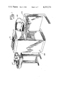
- FIG. 8 is a perspective view of the lower portion of the CPU cabinet shown with the exterior frame cut away to illustrate the assembled refrigeration and power-supply modules;
- FIG. 9 is a perspective view of the rear quarter of the CPU cabinet illustrating the position of the cooling air intake and exhaust ports
- FIG. 10 is a cross-sectional side elevation of the CPU cabinet (taken along the line 10--10 seen in FIG. 9) to depict the recirculating flow path of the refrigerated air used to cool the electronic circuit boards mounted within the card cage;
- FIG. 11 is a cross-sectional view looking downwardly at the refrigeration and power supply models from the line 11--11 seen in FIG. 10 to illustrate the flow-path of the forced air employed to cool the refrigeration and power supply modules;
- FIGS. 12 and 13 are perspective views of the CPU cabinet illustrating the independent removability of the power supply and refrigeration modules
- FIG. 14 is a perspective view of the CPU cabinet and console desk with portions thereof cut away to show the routing of input-output bus ribbon cables from the card cage to the junction box housing mounted on the inner rear wall of the console desk.
- TTL Transistor-Transistor Logic
- the TTL chips are in turn mounted on printed circuit boards which interconnect the chips by means of four or more conductive layers. Selected ones of the layers form closely spaced, facing planes to which the ground and non-zero voltage (Vcc) potentials are applied. These facing planes provide a low-resistance, distributed capacitance source of operating potentials to each chip.
- Vcc ground and non-zero voltage
- the Schottky TTL devices which are employed in the preferred embodiment of the invention generate relatively large amounts of heat.
- the total heat generated is particularly significant if high component density employed.
- this high heat density is controlled by recirculating refrigerated air maintained at a regulated temperature between the vertically aligned, spaced apart circuit boards.
- the circuit boards which make up the central processing unit, the input/output channels and a main memory of substantial capacity are advantageously housed together in a CPU cabinet whose exterior appearance is depicted in FIG. 1.
- a control panel indicated generally at 401, is positioned at the top of the substantially rectangular cabinet 402.
- a console desk indicated generally at 403, is attached to the side of the cabinet 402 and a combination key board input and CRT display terminal 405, which serves as the operator's system console, is positioned on the desk 403.
- a printer 407, which serves as the system recorder, is shown with the CPU unit in FIG. 1. (The system console 405 and the system recorder 407 are not part of the CPU, but are merely peripheral devices accessed through the input/output channels by operating system software).
- the cabinet which houses the CPU electronics is designed to permit easy access to the components which make up the system. All four sides of the cabinet are provided with exterior panels which, as will be described, are readily removable.
- a perspective view of the CPU cabinet with the exterior side panels removed appears in FIG. 2.
- the control panel 401 is hinge-mounted to the top of the interior cabinet frame, and is held in its fully raised position by a pair of braces 411.
- a card cage door 413 is hinged at its lower edge and may be pivoted downwardly to form a horizontal work shelf and to provide access to the front of the card cage pictured in more detail in FIGS. 3 through 7.
- the card cage comprises a pair of side panels 416 and 417, a bottom grill panel 419, three horizontal guide bars 421, 422 and 423 which extend across the top of the card cage, and a rear central guide bar 425.
- the grill plate 419 is shaped to form an array of regularly spaced guide channels separated by cooling apertures.
- circuit board cards are supported in spaced relation from one another by the grill 419, the guide bars 421-425 and by connectors 427, 428, which are rigidly affixed to the mother board 431 seen in FIG. 1.
- Two circuit boards are shown in FIGS. 6-8: the board 433 which is fully in place and plugged into the connector 427, and the board 435 which is shown only partly in place within the card cage.
- the upper guide bars 421, 422 and 423 each presents a row of downwardly and forwardly directed pointed fingers whose function is best seen in FIG. 6. These fingers facilitate the insertion of the circuit board by guiding the board into centered engagement with the connectors 427 and 428. As the board is inserted into the card cage, its lower edge is guided by the support channel formed in the grill plate 419, while its upper edge is guided by the guide bars 421-423. Just prior to engagement with the connectors 423 and 427, the board is further aligned by the forwardly projecting fingers on the guide bar 425, most clearly seen in FIG. 19.
- Guide bars 423 and 425 each provides channels indicated generally at 436 in FIG. 5 which receive and support flange members which extend from the top and bottom of the connectors 427 and 428.
- the closely packed components mounted on the circuit boards within the card cage generate substantial amounts of heat.
- this heat is removed by a forced flow of refrigerated air which circulates through the spaced apart circuit boards within the cage and through a cooling evaporator in a closed, recirculating air path.
- the evaporator forms part of a refrigeration module seen in the cut away view of FIG. 8.
- a motor 510 drives a pair of squirrel cage fans 512 which force air downwardly through an evaporator chamber indicated generally at 514.
- Tubes indicated at 516 carry refrigerant between the evaporator and a refrigeration compresser indicated generally at 520.
- the refrigeration module includes a filter drier 522, an accumulator 524, a radiator condenser chamber 525, a pan 530 for holding condensate from the evaporator 514 and a fan 535 which draws air through intake louvers seen at 540 in FIGS. 9 through 12.
- the cooling air driven by fan 535 then flows over the other components of the refrigeration unit as depicted in FIGS. 8 and 10 and over and through the components of the power supply module which includes a 12 volt power supply chassis, indicated generally at 551, and a 5 volt power supply chassis, indicated generally at 533. Cooling air driven by the fan 535 is expelled through the rear louvers 557 and through the side panel louvers 560.
- the power supply and refrigeration modules are independently removable from the CPU cabinet to facilitate repair and replacement.
- FIG. 13 of the drawings shows the air flow path within the refrigerated circuit board card cage.
- the temperature of the air flowing upwardly out of the card cage is monitored by a sensor seen at 560 in FIG. 10.
- the sensor 560 activates the compressor 520 whenever the temperature of air from the card cage exceeds a predetermined value (e.g. 25° C.).
- the evaporator chamber 514 is insulated from the remainder of the system by the insulating wall panels seen at 561 and 562 in FIG. 10.
- the card cage itself need not be thermally insulated since it is maintained at approximately room temperature.
- FIGS. 12 and 13 illustrate the manner in which the power supply module (indicated generally at 563 in FIG. 12) and the refrigeration module (indicated generally at 564 in FIG. 13) may be independently removed for repair or replacement.
- FIG. 14 of the drawing shows the CPU cabinet with circuit boards and input/output cables in place.
- These cables comprise ribbon conductors 570 which span laterally across the forward face of the card cage and through an aperture 571 where they are secured by a pressure plate 573.
- the ends of ribbon conductors are equipped with connectors which plug into a cross-connect panel 574.
- a second set of ribbon connectors 576 connect the panel 472 to a plurality of junction boxes indicated generally at 580 in FIG. 14.
- the junction boses 580 are mounted on the rear wall of the console desk 403.
- Junction boxes 580 interconnect the ribbon connectors 576 to conventional input/output wiring harness connectors at the ends of the cables 585 which connect the system to peripheral devices and controllers.
- the entire ribbon cable assembly is concealed behind removable panels during normal system use as depicted in FIG. 1.
Abstract
A cabinet for a central processing unit, made up of a card cage and refrigeration unit, for mounting and cooling electronic components on a group of vertically-aligned, closely-spaced circuit boards. A source of recirculating, forced, refrigerated air is employed to remove the heat from the highly concentrated electronic components. For ease of maintenance, the refrigeration unit and the power supply unit take the form of independently removable modules, and the removable circuit boards are mounted in a readily accessable card cage which incorporates formed card guides which facilitate card removal and insertion.
Description
This is a division of application Ser. No. 894,925, filed Apr. 10, 1978.
This invention relates to electronic data processing systems and more particularly to a central processing unit for use in such systems.
The central processing unit is advantageously instrumented with Large Scale Integration ("LSI") and Medium Scale Integration ("MSI") circuits. Such semiconductor "chips," or circuits, are selected from the Transistor-Transistor Logic ("TTL") family of devices.
TTL devices enjoy widespread use in electronic systems used in many different industries. As a result, many more types of functional subsystems have been embodied in TTL devices than in any of the other device families. Volume production of TTL devices amortizes their development cost and minimizes manufacturing process expenses. The result is that more functions in the processor can be implemented with LSI and MSI components, and these components are available at lower cost.
The widespread use of LSI and MSI devices in the processor results in improved system reliability and decreased design, debugging and servicing costs. Packing density increases and the number of interconnections external to the chips is reduced, thereby minimizing noise and other types of undesired effects.
Thus, the selection of TTL devices helps to create a highly compact, low-cost processor. The small size of the processor, itself an important advantage, contributes to the reduction of noise and other types of problems associated with the design of computers. As a result, special circuits which might otherwise be required to cope with such problems need not be added to the processor.
The central functions of a processor are sometimes carried out using so-called "Super High Speed" (Schottky) TTL circuits. By employing Schottky circuits, a substantial speed advantage over conventional TTL circuits is obtained.
This higher speed is obtained at a price: Schottky devices generate more heat than conventional high speed or standard TTL devices because they are not allowed to "saturate." The electronic hardware associated with one processor using super high speed TTL circuits is described in the copending parent and divisional applications identified in the previous section.
It is a principal object of the present invention to provide a central processing unit that is powerful but may be constructed at a low cost.
In accordance with one feature of the invention, heat generated by the highly concentrated electronic components is carried away by a forced flow of refrigerated air which is recirculated through and between the parallel, spaced-apart circuit boards. For ease of maintenance, the refrigeration unit, the power supply unit and the circuit boards take the form of independently removable modules. Novel circuit board support guides facilitate the removal testing and re-insertion of the boards.
These and other features to be described in more detail cooperatively interact to permit the construction of a highly compact, low cost processor.
These and other features and advantages of the present invention may be better understood through a consideration of the following detailed description. In the course of this description reference will frequently be made to the attached drawings, in which:
FIG. 1 is a perspective view showing the exterior appearance of a CPU cabinet which houses a central processing unit and other computer hardware, the CPU cabinet being shown with an adjoining operator's console desk and an operator message recording printer;
FIG. 2 is a perspective view of the CPU cabinet frame shown with the control panel raised and the card-cage access door lowered;
FIG. 3 is a front perspective view of the interior of the card-cage (from the vantage point 3 shown in FIG. 2);
FIG. 4 is a perspective view of the card-cage with a portion thereof cut away to better depict interior details;
FIG. 5 is a cross-sectional side-elevation of card-cage and control-panel assembly (taken along the line 5--5 seen in FIG. 3;
FIGS. 6 and 7 are top and bottom views of the card-cage guides (taken along the lines 6--6 and 7--7 respectively as seen in FIG. 5);
FIG. 8 is a perspective view of the lower portion of the CPU cabinet shown with the exterior frame cut away to illustrate the assembled refrigeration and power-supply modules;
FIG. 9 is a perspective view of the rear quarter of the CPU cabinet illustrating the position of the cooling air intake and exhaust ports;
FIG. 10 is a cross-sectional side elevation of the CPU cabinet (taken along the line 10--10 seen in FIG. 9) to depict the recirculating flow path of the refrigerated air used to cool the electronic circuit boards mounted within the card cage;
FIG. 11 is a cross-sectional view looking downwardly at the refrigeration and power supply models from the line 11--11 seen in FIG. 10 to illustrate the flow-path of the forced air employed to cool the refrigeration and power supply modules;
FIGS. 12 and 13 are perspective views of the CPU cabinet illustrating the independent removability of the power supply and refrigeration modules;
FIG. 14 is a perspective view of the CPU cabinet and console desk with portions thereof cut away to show the routing of input-output bus ribbon cables from the card cage to the junction box housing mounted on the inner rear wall of the console desk.
As previously discussed, the logical elements making up the processor are often advantageously instrumented using TTL (Transistor-Transistor Logic) integrated circuits. The TTL chips are in turn mounted on printed circuit boards which interconnect the chips by means of four or more conductive layers. Selected ones of the layers form closely spaced, facing planes to which the ground and non-zero voltage (Vcc) potentials are applied. These facing planes provide a low-resistance, distributed capacitance source of operating potentials to each chip.
As noted eariler, the Schottky TTL devices which are employed in the preferred embodiment of the invention generate relatively large amounts of heat. The total heat generated is particularly significant if high component density employed.
In accordance with a further feature of the invention, this high heat density is controlled by recirculating refrigerated air maintained at a regulated temperature between the vertically aligned, spaced apart circuit boards.
The circuit boards which make up the central processing unit, the input/output channels and a main memory of substantial capacity are advantageously housed together in a CPU cabinet whose exterior appearance is depicted in FIG. 1. A control panel, indicated generally at 401, is positioned at the top of the substantially rectangular cabinet 402. A console desk, indicated generally at 403, is attached to the side of the cabinet 402 and a combination key board input and CRT display terminal 405, which serves as the operator's system console, is positioned on the desk 403. A printer 407, which serves as the system recorder, is shown with the CPU unit in FIG. 1. (The system console 405 and the system recorder 407 are not part of the CPU, but are merely peripheral devices accessed through the input/output channels by operating system software).
The cabinet which houses the CPU electronics is designed to permit easy access to the components which make up the system. All four sides of the cabinet are provided with exterior panels which, as will be described, are readily removable. A perspective view of the CPU cabinet with the exterior side panels removed appears in FIG. 2. As there seen, the control panel 401 is hinge-mounted to the top of the interior cabinet frame, and is held in its fully raised position by a pair of braces 411. At the front of the cabinet a card cage door 413 is hinged at its lower edge and may be pivoted downwardly to form a horizontal work shelf and to provide access to the front of the card cage pictured in more detail in FIGS. 3 through 7.
As clearly seen in the perspective view of FIG. 4 the card cage comprises a pair of side panels 416 and 417, a bottom grill panel 419, three horizontal guide bars 421, 422 and 423 which extend across the top of the card cage, and a rear central guide bar 425.
The grill plate 419 is shaped to form an array of regularly spaced guide channels separated by cooling apertures. As seen in FIGS. 5 through 7, circuit board cards are supported in spaced relation from one another by the grill 419, the guide bars 421-425 and by connectors 427, 428, which are rigidly affixed to the mother board 431 seen in FIG. 1. Two circuit boards are shown in FIGS. 6-8: the board 433 which is fully in place and plugged into the connector 427, and the board 435 which is shown only partly in place within the card cage.
The upper guide bars 421, 422 and 423 each presents a row of downwardly and forwardly directed pointed fingers whose function is best seen in FIG. 6. These fingers facilitate the insertion of the circuit board by guiding the board into centered engagement with the connectors 427 and 428. As the board is inserted into the card cage, its lower edge is guided by the support channel formed in the grill plate 419, while its upper edge is guided by the guide bars 421-423. Just prior to engagement with the connectors 423 and 427, the board is further aligned by the forwardly projecting fingers on the guide bar 425, most clearly seen in FIG. 19.
Guide bars 423 and 425 each provides channels indicated generally at 436 in FIG. 5 which receive and support flange members which extend from the top and bottom of the connectors 427 and 428. When all of the circuit boards have been disengaged from the connectors 427 and 428, those connectors together with the mother board 431 to which they are attached, may be readily removed by sliding the combined unit horizontally through the support channels 436.
As noted previously, the closely packed components mounted on the circuit boards within the card cage generate substantial amounts of heat. In accordance with a feature of the present invention, this heat is removed by a forced flow of refrigerated air which circulates through the spaced apart circuit boards within the cage and through a cooling evaporator in a closed, recirculating air path. In addition, the evaporator forms part of a refrigeration module seen in the cut away view of FIG. 8. A motor 510 drives a pair of squirrel cage fans 512 which force air downwardly through an evaporator chamber indicated generally at 514. Tubes indicated at 516 carry refrigerant between the evaporator and a refrigeration compresser indicated generally at 520. Other portions of the refrigeration module include a filter drier 522, an accumulator 524, a radiator condenser chamber 525, a pan 530 for holding condensate from the evaporator 514 and a fan 535 which draws air through intake louvers seen at 540 in FIGS. 9 through 12. The cooling air driven by fan 535 then flows over the other components of the refrigeration unit as depicted in FIGS. 8 and 10 and over and through the components of the power supply module which includes a 12 volt power supply chassis, indicated generally at 551, and a 5 volt power supply chassis, indicated generally at 533. Cooling air driven by the fan 535 is expelled through the rear louvers 557 and through the side panel louvers 560. As seen in FIGS. 12 and 13, the power supply and refrigeration modules are independently removable from the CPU cabinet to facilitate repair and replacement.
FIG. 13 of the drawings shows the air flow path within the refrigerated circuit board card cage. The temperature of the air flowing upwardly out of the card cage is monitored by a sensor seen at 560 in FIG. 10. The sensor 560 activates the compressor 520 whenever the temperature of air from the card cage exceeds a predetermined value (e.g. 25° C.). The evaporator chamber 514 is insulated from the remainder of the system by the insulating wall panels seen at 561 and 562 in FIG. 10. The card cage itself need not be thermally insulated since it is maintained at approximately room temperature.
FIGS. 12 and 13 illustrate the manner in which the power supply module (indicated generally at 563 in FIG. 12) and the refrigeration module (indicated generally at 564 in FIG. 13) may be independently removed for repair or replacement.
FIG. 14 of the drawing shows the CPU cabinet with circuit boards and input/output cables in place. These cables comprise ribbon conductors 570 which span laterally across the forward face of the card cage and through an aperture 571 where they are secured by a pressure plate 573. The ends of ribbon conductors are equipped with connectors which plug into a cross-connect panel 574. A second set of ribbon connectors 576 connect the panel 472 to a plurality of junction boxes indicated generally at 580 in FIG. 14. The junction boses 580 are mounted on the rear wall of the console desk 403. Junction boxes 580 interconnect the ribbon connectors 576 to conventional input/output wiring harness connectors at the ends of the cables 585 which connect the system to peripheral devices and controllers. The entire ribbon cable assembly is concealed behind removable panels during normal system use as depicted in FIG. 1.
It is to be understood that the specific embodiment of the invention which has been described is merely illustrative of one application of the principles of the invention. Numerous modifications may be made to the preferred embodiment which has been disclosed without departing from the true spirit and scope of the invention.
Claims (6)
1. A card assembly for housing a plurality of removable electronic circuit boards comprising, in combination:
a pair of substantially planar, parallel, vertically oriented, spaced-apart side-panels;
a bottom grill plate extending between the bottom edges of said side panels, said grill plate being shaped to form an array of regularly spaced guide channels separated by cooling apertures;
connector support means extending between the rear edges of said side-panels for mounting a plurality of vertically oriented circuit board connectors, each of said connectors being adapted to engage with one of said cards; and
a plurality of spaced, horizontal guide support members extending between the upper edges of said side-panels, each of said support members defining a plurality of horizontally spaced, forwardly-directed, pointed guide fingers, adjacent pairs of said guide fingers being positioned to horizontally align one of said circuit boards for centering the engagement with one of said connectors.
2. A card cage assembly as set forth in claim 1 wherein said vertically oriented connectors include support flange members which extend from the top and bottom thereof, and wherein said connector support means include horizontally extending support channels shaped to receive and support said support flanges on said connectors.
3. A cabinet for housing a plurality of electronic circuit boards comprising, in combination:
an external wall;
a card cage assembly, fixed within said external wall, composed of a pair of side walls, a mother-board extending between the rear edges of said side walls for supporting a plurality of circuit board connectors, a movable access panel extending between the forward edges of said side walls, and a bottom grill plate extending between the bottom edges of said side walls, said grill plate being shaped to form an array of card support channels separated by cooling apertures; and
a refrigeration unit comprising an evaporator and a fan adapted to removably mate with said card cage assembly to form a closed recirculating air path, said evaporator being positioned adjacent one of said side walls and thermally insulated therefrom and from said exterior wall of said cabinet, and said fan being adapted to circulate air downwardly through said evaporator and upwardly through said card cage assembly.
4. A cabinet as set forth in claim 3 wherein said refrigeration unit further includes a compressor and a temperature sensor, said sensor being mounted in said closed recirculating air path for activating said compressor whenever the temperature in said air path exceeds a predetermined level.
5. A cabinet as set forth in claim 4 wherein said sensor is mounted substantially above said evaporator.
6. A cabinet as set forth in claim 5 wherein said sensor is mounted substantially above said card cage assembly.
Priority Applications (1)
| Application Number | Priority Date | Filing Date | Title |
|---|---|---|---|
| US06/155,695 US4352274A (en) | 1978-04-10 | 1980-06-02 | Circuit board mounting and cooling assembly |
Applications Claiming Priority (2)
| Application Number | Priority Date | Filing Date | Title |
|---|---|---|---|
| US89492578A | 1978-04-10 | 1978-04-10 | |
| US06/155,695 US4352274A (en) | 1978-04-10 | 1980-06-02 | Circuit board mounting and cooling assembly |
Related Parent Applications (1)
| Application Number | Title | Priority Date | Filing Date |
|---|---|---|---|
| US89492578A Division | 1978-04-10 | 1978-04-10 |
Publications (1)
| Publication Number | Publication Date |
|---|---|
| US4352274A true US4352274A (en) | 1982-10-05 |
Family
ID=26852534
Family Applications (1)
| Application Number | Title | Priority Date | Filing Date |
|---|---|---|---|
| US06/155,695 Expired - Lifetime US4352274A (en) | 1978-04-10 | 1980-06-02 | Circuit board mounting and cooling assembly |
Country Status (1)
| Country | Link |
|---|---|
| US (1) | US4352274A (en) |
Cited By (35)
| Publication number | Priority date | Publication date | Assignee | Title |
|---|---|---|---|---|
| US4446643A (en) * | 1981-07-20 | 1984-05-08 | Mitsubishi Denki Kabushiki Kaisha | Movable large display device |
| US4495780A (en) * | 1981-12-09 | 1985-01-29 | Hitachi, Ltd. | Cooling method and apparatus for hermetic type control box |
| FR2549980A1 (en) * | 1983-07-29 | 1985-02-01 | Thermetic Ste Nle | Thermal regulation device with fluid circulation. |
| US4514746A (en) * | 1983-12-01 | 1985-04-30 | Flakt Aktiebolag | Apparatus for cooling telecommunications equipment in a rack |
| US4683424A (en) * | 1984-11-07 | 1987-07-28 | Wehr Corporation | Apparatus for use in testing circuit boards |
| US4691274A (en) * | 1986-04-29 | 1987-09-01 | Modular Power Corporation | Modular electronic power supply |
| EP0288000A2 (en) * | 1987-04-24 | 1988-10-26 | Honeywell Bull Inc. | Compact packaging of electronic equipment within a small profile enclosure |
| US4797782A (en) * | 1985-10-03 | 1989-01-10 | Aktiebolaget Bofors | Arrangement in one or more units disposed in an outer unit |
| US4949031A (en) * | 1987-03-23 | 1990-08-14 | General Signal Corporation | Environmental stress screening apparatus for electronic products |
| US5027111A (en) * | 1988-07-07 | 1991-06-25 | Sentex Systems, Incorporated | Liquid-crystal display unit for electronic directory |
| US5823005A (en) * | 1997-01-03 | 1998-10-20 | Ncr Corporation | Focused air cooling employing a dedicated chiller |
| WO2001062060A1 (en) * | 2000-02-18 | 2001-08-23 | Rtkl Associates Inc. | Computer rack heat extraction device |
| US6285564B1 (en) * | 2000-03-24 | 2001-09-04 | Keystone Electronics Packaging, Inc. | Circuit card retainer assembly |
| US6493223B1 (en) * | 2000-06-28 | 2002-12-10 | Intel Corporation | Computer utilizing refrigeration for cooling |
| US6506111B2 (en) | 2001-05-16 | 2003-01-14 | Sanmina-Sci Corporation | Cooling airflow distribution device |
| US6557357B2 (en) | 2000-02-18 | 2003-05-06 | Toc Technology, Llc | Computer rack heat extraction device |
| US6574970B2 (en) | 2000-02-18 | 2003-06-10 | Toc Technology, Llc | Computer room air flow method and apparatus |
| US20040099747A1 (en) * | 2002-11-25 | 2004-05-27 | Johnson Rollie R. | Exhaust air removal system |
| US20050153649A1 (en) * | 2004-01-13 | 2005-07-14 | Bettridge James M. | Cabinet for computer devices with air distribution device |
| US20050170770A1 (en) * | 2002-11-25 | 2005-08-04 | American Power Conversion Corporation | Exhaust air removal system |
| US20050170772A1 (en) * | 2004-02-04 | 2005-08-04 | Fabian De Domenico | Air access panel |
| US20050219812A1 (en) * | 2004-04-01 | 2005-10-06 | Strobel Larry A | Environmental control system for personal computers |
| US20050225936A1 (en) * | 2002-03-28 | 2005-10-13 | Tony Day | Cooling of a data centre |
| US20060039107A1 (en) * | 2004-05-07 | 2006-02-23 | Daigaku Kumano | Cooling air intake structure and desk top computer |
| US20060276121A1 (en) * | 2003-05-13 | 2006-12-07 | American Power Conversion Corporation | Rack enclosure |
| US20070129000A1 (en) * | 2003-05-13 | 2007-06-07 | American Power Conversion Corporation | Rack enclosure |
| US20070171613A1 (en) * | 2006-01-20 | 2007-07-26 | Mcmahan Lianne M | Air removal unit |
| US20080158812A1 (en) * | 2006-12-27 | 2008-07-03 | Hakan Erturk | Method and system to cool memory |
| US7681410B1 (en) | 2006-02-14 | 2010-03-23 | American Power Conversion Corporation | Ice thermal storage |
| US20100149754A1 (en) * | 2007-03-14 | 2010-06-17 | Zonit Structured Solutions, Llc | Air-based cooling for data center rack |
| US20100197824A1 (en) * | 2007-09-26 | 2010-08-05 | Peter Bissinger | Methacrylate based monomers containing a urethane linkage, process for production and use thereof |
| US20110216503A1 (en) * | 2009-01-08 | 2011-09-08 | Shane Ramodien | Electronic equipment housing |
| US20130189916A1 (en) * | 2012-01-20 | 2013-07-25 | Delta Electronics, Inc. | Rack system and ventilation apparatus thereof |
| US9952103B2 (en) | 2011-12-22 | 2018-04-24 | Schneider Electric It Corporation | Analysis of effect of transient events on temperature in a data center |
| US11076507B2 (en) | 2007-05-15 | 2021-07-27 | Schneider Electric It Corporation | Methods and systems for managing facility power and cooling |
Citations (5)
| Publication number | Priority date | Publication date | Assignee | Title |
|---|---|---|---|---|
| US2187011A (en) * | 1937-03-13 | 1940-01-16 | Paul F Braden | Cooling means for an electrical apparatus |
| US3396780A (en) * | 1966-06-23 | 1968-08-13 | Udylite Corp | Add-on cooling system |
| US3723823A (en) * | 1971-11-30 | 1973-03-27 | Gen Electric | Printed circuit board guide |
| US3925710A (en) * | 1974-07-01 | 1975-12-09 | Us Navy | General purpose electronic interface equipment package |
| US4277815A (en) * | 1979-06-15 | 1981-07-07 | Westinghouse Electric Corp. | Replaceable air seal for force cooled removable electronic units |
-
1980
- 1980-06-02 US US06/155,695 patent/US4352274A/en not_active Expired - Lifetime
Patent Citations (5)
| Publication number | Priority date | Publication date | Assignee | Title |
|---|---|---|---|---|
| US2187011A (en) * | 1937-03-13 | 1940-01-16 | Paul F Braden | Cooling means for an electrical apparatus |
| US3396780A (en) * | 1966-06-23 | 1968-08-13 | Udylite Corp | Add-on cooling system |
| US3723823A (en) * | 1971-11-30 | 1973-03-27 | Gen Electric | Printed circuit board guide |
| US3925710A (en) * | 1974-07-01 | 1975-12-09 | Us Navy | General purpose electronic interface equipment package |
| US4277815A (en) * | 1979-06-15 | 1981-07-07 | Westinghouse Electric Corp. | Replaceable air seal for force cooled removable electronic units |
Cited By (78)
| Publication number | Priority date | Publication date | Assignee | Title |
|---|---|---|---|---|
| US4446643A (en) * | 1981-07-20 | 1984-05-08 | Mitsubishi Denki Kabushiki Kaisha | Movable large display device |
| US4495780A (en) * | 1981-12-09 | 1985-01-29 | Hitachi, Ltd. | Cooling method and apparatus for hermetic type control box |
| FR2549980A1 (en) * | 1983-07-29 | 1985-02-01 | Thermetic Ste Nle | Thermal regulation device with fluid circulation. |
| US4514746A (en) * | 1983-12-01 | 1985-04-30 | Flakt Aktiebolag | Apparatus for cooling telecommunications equipment in a rack |
| US4683424A (en) * | 1984-11-07 | 1987-07-28 | Wehr Corporation | Apparatus for use in testing circuit boards |
| US4797782A (en) * | 1985-10-03 | 1989-01-10 | Aktiebolaget Bofors | Arrangement in one or more units disposed in an outer unit |
| US4691274A (en) * | 1986-04-29 | 1987-09-01 | Modular Power Corporation | Modular electronic power supply |
| US4949031A (en) * | 1987-03-23 | 1990-08-14 | General Signal Corporation | Environmental stress screening apparatus for electronic products |
| EP0288000A3 (en) * | 1987-04-24 | 1989-10-18 | Honeywell Bull Inc. | Compact packaging of electronic equipment within a small profile enclosure |
| EP0288000A2 (en) * | 1987-04-24 | 1988-10-26 | Honeywell Bull Inc. | Compact packaging of electronic equipment within a small profile enclosure |
| US5027111A (en) * | 1988-07-07 | 1991-06-25 | Sentex Systems, Incorporated | Liquid-crystal display unit for electronic directory |
| US5252955A (en) * | 1988-07-07 | 1993-10-12 | Davis William R | Liquid-crystal display unit for electronic directory |
| US5823005A (en) * | 1997-01-03 | 1998-10-20 | Ncr Corporation | Focused air cooling employing a dedicated chiller |
| US6745579B2 (en) | 2000-02-18 | 2004-06-08 | Toc Technology, Llc | Computer room air flow method and apparatus |
| US6722151B2 (en) | 2000-02-18 | 2004-04-20 | Toc Technology, Llc | Computer rack heat extraction device |
| US6494050B2 (en) | 2000-02-18 | 2002-12-17 | Toc Technology, Llc | Computer rack heat extraction device |
| WO2001062060A1 (en) * | 2000-02-18 | 2001-08-23 | Rtkl Associates Inc. | Computer rack heat extraction device |
| US6557357B2 (en) | 2000-02-18 | 2003-05-06 | Toc Technology, Llc | Computer rack heat extraction device |
| US6574970B2 (en) | 2000-02-18 | 2003-06-10 | Toc Technology, Llc | Computer room air flow method and apparatus |
| US6285564B1 (en) * | 2000-03-24 | 2001-09-04 | Keystone Electronics Packaging, Inc. | Circuit card retainer assembly |
| US6493223B1 (en) * | 2000-06-28 | 2002-12-10 | Intel Corporation | Computer utilizing refrigeration for cooling |
| US6652374B2 (en) | 2001-05-16 | 2003-11-25 | Sanmina-Sci Corporation | Cooling airflow distribution device |
| US6652373B2 (en) | 2001-05-16 | 2003-11-25 | Sanmina-Sci Corporation | Cooling airflow distribution device |
| US7309279B2 (en) | 2001-05-16 | 2007-12-18 | Sanmina-Sci Corporation | Cooling airflow distribution device |
| US6506111B2 (en) | 2001-05-16 | 2003-01-14 | Sanmina-Sci Corporation | Cooling airflow distribution device |
| US20040180620A1 (en) * | 2001-05-16 | 2004-09-16 | Sharp Anthony C | Cooling airflow distribution device |
| US7011576B2 (en) | 2001-05-16 | 2006-03-14 | Sanmina Sci Corporation | Cooling airflow distribution device |
| US20050250435A1 (en) * | 2001-05-16 | 2005-11-10 | Sharp Anthony C | Cooling airflow distribution device |
| US20050225936A1 (en) * | 2002-03-28 | 2005-10-13 | Tony Day | Cooling of a data centre |
| US20090173473A1 (en) * | 2002-03-28 | 2009-07-09 | American Power Conversion Corporation | Data center cooling |
| US7534167B2 (en) | 2002-03-28 | 2009-05-19 | American Power Conversion Corporation | Data center cooling |
| US8157626B2 (en) | 2002-03-28 | 2012-04-17 | American Power Conversion Corporation | Data center cooling |
| US7867070B2 (en) | 2002-03-28 | 2011-01-11 | American Power Conversion Corporation | Data center cooling |
| US20070213000A1 (en) * | 2002-03-28 | 2007-09-13 | American Power Conversion | Data Center Cooling |
| US9392733B2 (en) | 2002-03-28 | 2016-07-12 | Schneider Electric It Corporation | Data center cooling |
| US20110094714A1 (en) * | 2002-03-28 | 2011-04-28 | American Power Conversion Corporation | Data center cooling |
| US7878889B2 (en) | 2002-03-28 | 2011-02-01 | American Power Conversion Corporation | Data center cooling |
| US20040099747A1 (en) * | 2002-11-25 | 2004-05-27 | Johnson Rollie R. | Exhaust air removal system |
| US20050170770A1 (en) * | 2002-11-25 | 2005-08-04 | American Power Conversion Corporation | Exhaust air removal system |
| US7752858B2 (en) * | 2002-11-25 | 2010-07-13 | American Power Conversion Corporation | Exhaust air removal system |
| US20090308579A1 (en) * | 2002-11-25 | 2009-12-17 | American Power Conversion Corporation | Exhaust air removal system |
| US7500911B2 (en) | 2002-11-25 | 2009-03-10 | American Power Conversion Corporation | Exhaust air removal system |
| US8544289B2 (en) | 2002-11-25 | 2013-10-01 | Schneider Electric It Corporation | Exhaust air removal system |
| US20070129000A1 (en) * | 2003-05-13 | 2007-06-07 | American Power Conversion Corporation | Rack enclosure |
| US20110045759A1 (en) * | 2003-05-13 | 2011-02-24 | American Power Conversion Corporation | Rack enclosure |
| US20060276121A1 (en) * | 2003-05-13 | 2006-12-07 | American Power Conversion Corporation | Rack enclosure |
| US7878888B2 (en) | 2003-05-13 | 2011-02-01 | American Power Conversion Corporation | Rack enclosure |
| US8087979B2 (en) | 2003-05-13 | 2012-01-03 | American Power Conversion Corporation | Rack enclosure |
| US8403736B2 (en) | 2003-05-13 | 2013-03-26 | Schneider Electric It Corporation | Rack enclosure |
| US7226353B2 (en) | 2004-01-13 | 2007-06-05 | Power Of 4, Llc | Cabinet for computer devices with air distribution device |
| US20050153649A1 (en) * | 2004-01-13 | 2005-07-14 | Bettridge James M. | Cabinet for computer devices with air distribution device |
| US20050248043A1 (en) * | 2004-01-13 | 2005-11-10 | Bettridge James M | Cabinet for computer devices with air distribution device |
| US7074123B2 (en) | 2004-01-13 | 2006-07-11 | Power Of 4, L.L.C. | Cabinet for computer devices with air distribution device |
| US20050170772A1 (en) * | 2004-02-04 | 2005-08-04 | Fabian De Domenico | Air access panel |
| US20050219812A1 (en) * | 2004-04-01 | 2005-10-06 | Strobel Larry A | Environmental control system for personal computers |
| US7236359B2 (en) * | 2004-04-01 | 2007-06-26 | Strobel Larry A | Environmental control system for personal computers |
| US7245486B2 (en) * | 2004-05-07 | 2007-07-17 | Sony Corporation | Cooling air intake structure and desk top computer |
| US20060039107A1 (en) * | 2004-05-07 | 2006-02-23 | Daigaku Kumano | Cooling air intake structure and desk top computer |
| US7791875B2 (en) | 2004-05-07 | 2010-09-07 | Sony Corporation | Cooling air intake structure and desk top computer |
| US20070236879A1 (en) * | 2004-05-07 | 2007-10-11 | Sony Corporation | Cooling air intake structure and desk top computer |
| US7862410B2 (en) | 2006-01-20 | 2011-01-04 | American Power Conversion Corporation | Air removal unit |
| US20070171613A1 (en) * | 2006-01-20 | 2007-07-26 | Mcmahan Lianne M | Air removal unit |
| US20110143644A1 (en) * | 2006-01-20 | 2011-06-16 | American Power Conversion Corporation | Air removal unit |
| US8210914B2 (en) | 2006-01-20 | 2012-07-03 | American Power Coversion Corporation | Air removal unit |
| US7681410B1 (en) | 2006-02-14 | 2010-03-23 | American Power Conversion Corporation | Ice thermal storage |
| US8650896B2 (en) | 2006-02-14 | 2014-02-18 | Schneider Electric It Corporation | Ice thermal storage |
| US20100154438A1 (en) * | 2006-02-14 | 2010-06-24 | American Power Conversion Corporation | Ice thermal storage |
| US7457116B2 (en) * | 2006-12-27 | 2008-11-25 | Intel Corporation | Method and system to cool memory |
| US20080158812A1 (en) * | 2006-12-27 | 2008-07-03 | Hakan Erturk | Method and system to cool memory |
| US8453471B2 (en) * | 2007-03-14 | 2013-06-04 | Zonit Structured Solutions, Llc | Air-based cooling for data center rack |
| US20100149754A1 (en) * | 2007-03-14 | 2010-06-17 | Zonit Structured Solutions, Llc | Air-based cooling for data center rack |
| US9618270B2 (en) | 2007-03-14 | 2017-04-11 | Zonit Structured Solutions, Llc | Air-based cooling for data center rack |
| US11076507B2 (en) | 2007-05-15 | 2021-07-27 | Schneider Electric It Corporation | Methods and systems for managing facility power and cooling |
| US11503744B2 (en) | 2007-05-15 | 2022-11-15 | Schneider Electric It Corporation | Methods and systems for managing facility power and cooling |
| US20100197824A1 (en) * | 2007-09-26 | 2010-08-05 | Peter Bissinger | Methacrylate based monomers containing a urethane linkage, process for production and use thereof |
| US20110216503A1 (en) * | 2009-01-08 | 2011-09-08 | Shane Ramodien | Electronic equipment housing |
| US9952103B2 (en) | 2011-12-22 | 2018-04-24 | Schneider Electric It Corporation | Analysis of effect of transient events on temperature in a data center |
| US20130189916A1 (en) * | 2012-01-20 | 2013-07-25 | Delta Electronics, Inc. | Rack system and ventilation apparatus thereof |
Similar Documents
| Publication | Publication Date | Title |
|---|---|---|
| US4352274A (en) | Circuit board mounting and cooling assembly | |
| US20220292044A1 (en) | Modular mass storage system | |
| US4672509A (en) | Air cooling assembly in an electronic system enclosure | |
| US4739445A (en) | Electronic computer cabinetry having fan and power supply drawers and connector port arrangement | |
| US6208522B1 (en) | Computer chassis assembly with a single center pluggable midplane board | |
| US7355852B2 (en) | Modular liquid cooling of electronic assemblies | |
| US3925710A (en) | General purpose electronic interface equipment package | |
| US3691432A (en) | Computer package cabinet and module system | |
| US5497288A (en) | Apparatus for tilted serial cooling in an electronic system | |
| US7420805B2 (en) | Method and apparatus for rack mounting computer components | |
| US5287009A (en) | Circuit module fan assembly | |
| US6836030B2 (en) | Rack mountable computer component power distribution unit and method | |
| US4149218A (en) | Minimum delay module assembly | |
| US9934824B2 (en) | Hard disk drive assembly with field-separable mechanical module and drive control | |
| US20050281005A1 (en) | Modular chassis divided along a midplane and cooling system therefor | |
| WO2007061713A2 (en) | Power supply cooling system | |
| EP0031419B1 (en) | Air-cooled hybrid electronic package | |
| US8804278B1 (en) | Cooling of hard disk drives with separate mechanical module and drive control module | |
| GB2025144A (en) | Device for a data processing system | |
| US6330156B1 (en) | Card support and cooler bracket | |
| US8908326B1 (en) | Hard disk drive mechanical modules with common controller | |
| US11317533B2 (en) | Heat sink arrangements for data storage systems | |
| CN111655016B (en) | Partitioned heat dissipation plug-in box and cabinet | |
| CN112527055A (en) | Computer case and computer system | |
| JP2828058B2 (en) | Electronic equipment cooling structure |
Legal Events
| Date | Code | Title | Description |
|---|---|---|---|
| STCF | Information on status: patent grant |
Free format text: PATENTED CASE |