US4366756A - Electronic tractor guidance system - Google Patents
Electronic tractor guidance system Download PDFInfo
- Publication number
- US4366756A US4366756A US06/185,410 US18541080A US4366756A US 4366756 A US4366756 A US 4366756A US 18541080 A US18541080 A US 18541080A US 4366756 A US4366756 A US 4366756A
- Authority
- US
- United States
- Prior art keywords
- steering
- tractor
- signal
- generating
- control signal
- Prior art date
- Legal status (The legal status is an assumption and is not a legal conclusion. Google has not performed a legal analysis and makes no representation as to the accuracy of the status listed.)
- Expired - Lifetime
Links
- 230000000694 effects Effects 0.000 claims abstract description 5
- 238000012937 correction Methods 0.000 claims description 21
- 230000035945 sensitivity Effects 0.000 claims description 4
- 238000000034 method Methods 0.000 claims 2
- 230000036962 time dependent Effects 0.000 claims 1
- 238000010586 diagram Methods 0.000 description 5
- 238000006073 displacement reaction Methods 0.000 description 2
- 238000007792 addition Methods 0.000 description 1
- 239000003990 capacitor Substances 0.000 description 1
- 238000012217 deletion Methods 0.000 description 1
- 230000037430 deletion Effects 0.000 description 1
- 210000002969 egg yolk Anatomy 0.000 description 1
- 230000000977 initiatory effect Effects 0.000 description 1
- 238000009434 installation Methods 0.000 description 1
- 238000004519 manufacturing process Methods 0.000 description 1
- 238000012986 modification Methods 0.000 description 1
- 230000004048 modification Effects 0.000 description 1
- 239000004065 semiconductor Substances 0.000 description 1
- 239000002689 soil Substances 0.000 description 1
- 238000006467 substitution reaction Methods 0.000 description 1
Images


Classifications
-
- G—PHYSICS
- G05—CONTROLLING; REGULATING
- G05D—SYSTEMS FOR CONTROLLING OR REGULATING NON-ELECTRIC VARIABLES
- G05D1/00—Control of position, course or altitude of land, water, air, or space vehicles, e.g. automatic pilot
- G05D1/02—Control of position or course in two dimensions
- G05D1/021—Control of position or course in two dimensions specially adapted to land vehicles
- G05D1/0227—Control of position or course in two dimensions specially adapted to land vehicles using mechanical sensing means, e.g. for sensing treated area
Definitions
- This invention relates generally to automatic guidance control systems for controlling the direction of travel of a moving vehicle to follow a prescribed path. More particularly, the present invention relates to an automatic guidance control system for guiding an agricultural tractor to follow a previously plowed furrow or guiding means in a field under cultivation.
- Prior-art tractor guidance systems have been constructed to guide the path of the tractor to follow a previously plowed furrow.
- these prior-art guidance systems are, for the most part, complicated mechanical-hydraulic contrivances that lack the sensitivity necessary to optimally control the direction of travel of the tractor to follow a previously plowed furrow.
- these types of prior-art devices are only effective when used on tractors which have closed center hydraulic systems. Not all tractors come so equipped. Another problem not solved by these prior-art devices occurs from external forces which act on the tractor and the implements being pulled to force the tractor to deviate in its direction of travel, without a change in the tractor's steering direction.
- an automatic guidance system for controlling the direction of travel of a tractor along a guide path.
- the guidance system consists of two sensors, a direction sensor connected to the tractor for sensing the direction of the guide path relative to the direction of travel of the tractor, and a tractor steering sensor connected to the steering means of the tractor to detect the steering direction of the tractor.
- Both the direction sensor and the tractor steering sensor are sensitive rotary variable differential transformers that produce DC output voltages proportional to the angular position of the sensor's shaft.
- a furrow follower assembly controls the angular position of the direction sensor's shaft to produce a path direction signal that indicates the relative direction of the path to the direction of travel of the tractor.
- angular rotation of the sensor's shaft is controlled by rotation of the front steering wheels of the tractor. In this manner, the steering direction of the tractor is sensed to generate a steering direction signal.
- the guidance system further includes a tractor steering means attached to the steering column of the tractor to provide rotation of the steering wheel under control of the guidance system.
- the tractor steering means includes a permanent magnetic DC motor coupled to the steering column through a gearing arrangement or by sprockets and chain.
- a control means that responds to the path direction signal from the direction sensor and the steering direction signal from the tractor steering sensor to produce a steering control signal.
- the steering control signal is a digital signal having a duty cycle which varies with the magnitude of the difference between the path direction signal and the steering direction signal. A steering change to the tractor is effected if the duty cycle of the steering signal deviates from a 50% duty cycle.
- control means amplifies the signals from the two sensors to respectively obtain the path direction signal and the steering direction signal.
- a bipolar offset control voltage is generated and subtracted from the path direction signal to produce a furrow error signal.
- the bipolar offset control voltage adjusts for the side forces acting on the tractor to alter the tractor's direction of travel even though a change in the steering direction of tractor was not made.
- a steering error amplifier responds to the steering direction signal and the furrow error signal to generate a steering error signal that ultimately will determine whether a steering change will occur to the tractor.
- a convergence control oscillator is provided for generating a bipolar convergence frequency signal that is compared with the steering error signal to produce the variable duty cycle steering control signal.
- a comparison means is provided to compare the convergence frequency signal and the steering error signal.
- the convergence frequency signal is a bipolar triangular wave form. When the magnitude of this convergence frequency signal is greater than the steering error signal, a digital logic state is generated for the steering control signal, and if the magnitude of the convergence frequency signal is less than the steering error signal, the opposite digital logic state is produced.
- a right-turn signal is generated to the DC motor controlling the steering column of the tractor, while in the opposite logic state, a left-turn control signal is delivered to the motor.
- a command to the steering motor to both turn right and to turn left is given. If the duty cycle of the steering control signal is 50%, no net effective turn occurs in the steering. However, any variation of the duty cycle, either above or below 50%, will respectively result in an effective net turn to the right or to the left.
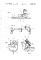
- FIG. 1 is a side view of the furrow follower assembly attached to the front end of a typical tractor;
- FIG. 2 is a top view of a typical steering linkage arrangement showing the steering sensor connected for sensing the steering direction of the tractor;
- FIG. 3 is a view from above of the direction sensor coupled to the furrow follower sensing boom mounted to the front end of the tractor;
- FIG. 4 is an illustration of the control motor assembly for controlling the steering column of the tractor
- FIG. 5 is a schematic blocked diagram of the control means of the present invention.
- FIG. 6 is a more detailed circuit diagram of a portion of the control means illustrated in FIG. 5;
- FIG. 7 is a detailed circuit diagram of the power amplifier that provides the drive signal to the steering control motor illustrated in FIG. 4;
- FIG. 8 is an illustration of various electrical signal wave forms which show how the steering control signal is generated by the control means illustrated in FIG. 5.
- a furrow follower assembly 2 for sensing the direction of a guide path, such as a previously plowed furrow.
- a more detailed description of the furrow follower assembly 2 is given in U.S. Pat. No. 4,165,796 issued to Petz and such disclosure is herein incorporated by reference.
- a boom 6 has attached at its sensing end two dish shaped plates 4 which lie within and follow the tapering sides of a plowed furrow. Connected to the opposite end of boom 6 is direction sensor 12.
- Direction sensor 12 is mounted to the plate 14 such that side-to-side displacement of the boom 6 relative to the direction of travel of the tractor produces a rotation of the shaft of sensor 12.
- a DC analog voltage is produced on the output of sensor 12 as a function of the angular position of its shaft. Therefore, rotation of the angular shaft by the furrow follower sensing assembly 2 produces a change in the voltage generated by sensor 12.
- the furrow sensing assembly 2 is provided with a hydraulic piston 8 actuated in response to electrical signals to raise and lower the boom 6. In operation, the boom 6 is lowered so that the dish plates 4 will be contacting the furrow along which the tractor will be guided. Any deviation of the direction of travel of the tractor to the direction of the path will be reflected as a change in the output of sensor 12.
- the front steering linkages of the tractor are diagrammatically illustrated showing how the tractor steering sensor 22 is coupled to the steering linkages of the tractors front wheels to provide a DC error signal indicating the steering direction of the tractor.
- the steering direction of the tractor will be the direction of travel of the tractor.
- the tractor steering may not necessarily be in the direction of travel of the tractor.
- the steering of the tractor In order to overcome the side forces, the steering of the tractor must be effected in a direction to overcome these side forces. By so doing, the direction of travel of the tractor can be maintained in the desired direction.
- Steering sensor 22 is identical to sensor 12, and functions to produce a DC analog voltage as a function of the angular position of the sensors input shaft. By modulating the angular position of sensor 22's shaft as a function of the front wheel positions, a feedback error signal can be generated as a function of the steering direction of the tractor.
- sensors 12 and 22 are both sold by Schaevitz Engineering as their model R30D rotary variable differential transformers. These units were selected because they exhibited zero volts out when the angular position of the shaft is at a reference position, regardless of variations in the supply voltages delivered to the units. This predictability in the output voltage eliminates the need for complicated offset error adjustments in the electronics to compensate for system power supply variations.
- FIG. 3 a view of the sensor 12 and boom 6 as viewed from above, is illustrated.
- the boom 6 provides a U-shaped yolk connection to the housing of the sensor 12, while the shaft 16 of the sensor is fixedly secured to the frame of the tractor by bracket 20.
- Brackets 18, 14 provide mechanical support for the sensor assembly while permitting the housing of sensor 12 to rotate relative to its shaft 16. Should the direction of travel of the tractor deviate from the direction of the path, the housing of sensor 12 will be rotated by displacement of the boom 6 attached thereto. This rotation will be reflected as a change in the DC output voltage from the sensor 12.
- a permanent magnet DC servo motor 34 is shown connected to the steering column 36 of the tractor via a combination of sprockets 40, 42 connected together by a continuous chain 38.
- Sprocket 40 is mounted to the shaft of the DC motor 34, while sprocket 32 is connected to the steering shaft 36 of the tractor.
- Continuous chain 38 transfers the torque produced by the DC motor 34 to the steering column 36. In this manner, rotation of steering motor 34 produces rotation of the steering column 36.
- the permanent magnet DC motor is an Indiana General model 4010-W19-01.
- FIG. 5 a block diagram of the control means of the automatic guidance system of the invention is shown.
- the furrow sensing assembly 2, including the boom 6 and furrow sensing dishes 4, are shown sensing the direction of furrow 1.
- the output signal from the sensor 12 contained in the furrow sensing assembly 2 is inputted into error amplifier 42.
- the feedback error signal from the steering sensor 22, illustrated in FIG. 2 is inputted to a feedback amplifier 50 identical to the error amplifier 42.
- Amplifier 42 produces the path direction signal on its output, while feedback amplifer 50 produces the steering direction signal 5.
- an offset control 44 which generates a bipolar switch selectable control offset voltage to compensate for the side forces acting on the tractor which tend to cause the direction of travel of the tractor to change.
- This offset control voltage is inputted with the path direction signal to a differencing amplifier 46 which subtracts the two signals and produces the furrow error signal 3 on its output.
- the furror error signal 3 is then inputted, along with the steering direction signal 5 from feedback amplifier 50 into a sum and difference amplifier 48.
- Sum or difference amplifier 48 generates both the sum of the furrow error signal 3 and the steering direction signal 5, and the difference of these two signals. Jumper selection (see FIG.
- the steering sensing assembly 22 is provided on the output of the sum or difference amplifier 48 to enable either combination of the furrow error signal 3 and the steering direction signal 5 to be selected as the steering error signal 7.
- the steering sensing assembly 22 may not be possible to mount the steering sensing assembly 22 to produce a particular direction change in its output signal for a particular change in the steering direction of the tractor.
- the magnitude of the change as a function of the steering change will be the same, its polarity may be different from tractor to tractor. Accordingly, by providing both a sum and a differencing function in the sum or difference amplifier 48, the appropriate combination of the furrow error signal 3 and a steering direction signal 5 can be selected to obtain the required steering error signal 7.
- the steering error signal 7 is shown inputted along with convergence frequency signal 9 from convergence control oscillator 41 to right/left turn comparator 52.
- the function of comparator 52 is to produce a digital right/left turn signal 11 in which one logic state of the digital signal occurs when the magnitude of the convergence frequency signal 9 is greater than the magnitude of steering error signal 7, while the opposite logic state obtains when frequency signal 9 is less than the steering error signal 7.
- the frequency of the right/left turn signal will be equal to the fundamental frequency of the convergence frequency signal 9.
- the convergence control oscillator output frequency is approximately one kilohertz (1 KHz).
- the right/left turn signal 11 is inputted to both right turn on unit 54 and left turn on unit 56.
- These two units function to provide digital signals on their respective output where a logic one on the output of one unit produces a steering turn in its respective direction while the output of the opposite unit will not produce a steering turn, i.e., its output will be at a logic zero.
- This condition alternately changes for each unit as the logic states of their respective outputs change.
- unit 54 is at a logic one
- unit 56 is at a logic zero.
- unit 56 is at a logic one.
- the outputs from right turn on 54 and left turn on 56 are applied to power amplifier 62 via delay units 58 and 60, respectively.
- Power amplifier 62 amplifies the right turn on 13 and left turn on 15 output signals to provide the steering control signals to the steering control motor 34.
- FIGS. 6 and 7 a detailed circuit diagram of the control means illustrated in FIG. 5 is shown.
- the operations of the circuits shown in FIGS. 6 and 7 are well known to those of ordinary skill in the art, and a detailed description of their operations will not be provided herein. It will be clear to those of ordinary skill in the art that the values of the various circuit components and voltage associated with the analog amplifiers and transistors depicted in FIGS. 6 and 7 will vary in dependence upon the intended use. In a presently preferred embodiment used in connection with an automatic tractor guidance system for controlling the direction of travel of a tractor, the table below sets out exemplary values which have been found satisfactory.
- FIG. 8(a), (b) and (c) signal waveforms of the steering error signal 7 outputted by the sum or difference amplifier 48 and the convergence control oscillator frequency signal 9 are shown superimposed in the same drawing.
- FIG. 8(a) illustrates a condition when the steering error signal 7 is zero volts in magnitude and where the voltage swing of convergence frequency signal 9 is ⁇ E.
- the right/left turn signal 11 is generated as a function of the comparison of the steering error signal 7 and the convergence frequency signal 9 in the right/left turn comparator 52.
- the convergence frequency signal 9 is greater than the magnitude of the steering error signal 7, a logic one is produced for the right/left turn signal 11.
- a logic zero state is generated.
- FIGS. 8(b) and 8(c) the operating conditions for a steering error signal 7 having a positive polarity and a steering error signal 7 having a negative polarity are respectively illustrated.
- a duty cycle less than 50% is generated. This results in a net steering change in the left direction.
- the steering error signal 7 is negative, a net right turn is effected.
- the control means illustrated in FIG. 5 functions to control the direction of steering of the tractor to cause the right/left turn signal 11 to exhibit a 50% duty cycle.
- the rate at which a steering correction can be made to the steering of the tractor is a function of the magnitude of the convergence frequency signal 9, a lower magnitude causing a faster steering change than a high magnitude signal.
- the present invention functions to sense both the direction of a guide path and the steering direction of the tractor to produce an error signal that is compared with an oscillator frequency signal.
- the result of this comparison produces a digital waveform in which the two logic states are assigned the control function of initiating a right or a left turn.
- a 50% duty cycle in the digital waveform will produce no net turning effect in the steering direction of the tractor. Deviations from the 50% duty cycle brought about by a deviation in the direction of travel of the tractor and the direction of the guide furrow result in a steering correction to bring the duty cycle back to 50%.
Abstract
Description
______________________________________
TABLE OF COMPONENT VALUES
______________________________________
Resistors
Component         Value (ohms)
______________________________________
R57, 60, 62, 69   10
R42, 46, 48, 49, 51, 54,
56, 58, 59, 61, 64, 65, 66
                  1K
R16               2.2K
R17,              10K        varibale
R7, R12, 31, 39, 43, 44,
                  10K        fixed
45, 47, 50, 52, 53, 52, 55, 63
R68               22K
R19               33K
R35, 36           47K
R7, 14, 18        100K       variable
All remaining resistors not listed
                  100K       fixed
______________________________________
Capacitors
Component         Value (f)
______________________________________
C1, 2             .1
C3                1
C4                220
C5, 6             .01
C7                10
C8                .047
Amplifiers
A1-A12            LM324      (National
                             Semiconductor)
A13-A16           3302       (Motorola)
66, 68, 70, A17-A20
                  1411       (Motorola)
Q2, Q6            SK3182     (RCA)
Q3, Q7            SK3183     (RCA)
Q1, Q5            2N6378     (Motorola)
Q4, Q8            2N6276     (Motorola)
Diodes
D1, D2            IN912
D3-D6             IN4005
Relay
64                W171-DIP19 (MAGNE-
                             CRAFT)
______________________________________
Claims (15)
Priority Applications (6)
| Application Number | Priority Date | Filing Date | Title |
|---|---|---|---|
| US06/185,410 US4366756A (en) | 1980-09-09 | 1980-09-09 | Electronic tractor guidance system |
| CA000384107A CA1158341A (en) | 1980-09-09 | 1981-08-18 | Electronic tractor guidance system |
| GB8125304A GB2083662B (en) | 1980-09-09 | 1981-08-19 | Electronic tractor guidance system |
| MX189011A MX151151A (en) | 1980-09-09 | 1981-09-03 | IMPROVEMENTS IN THE AUTOMATIC GUIDE SYSTEM TO CONTROL THE TRACING ROAD ORIENTATION |
| DE19813135512 DE3135512A1 (en) | 1980-09-09 | 1981-09-08 | ELECTRONIC TRACTOR GUIDE SYSTEM |
| JP56141122A JPS5783812A (en) | 1980-09-09 | 1981-09-09 | Tractor guide apparatus |
Applications Claiming Priority (1)
| Application Number | Priority Date | Filing Date | Title |
|---|---|---|---|
| US06/185,410 US4366756A (en) | 1980-09-09 | 1980-09-09 | Electronic tractor guidance system |
Publications (1)
| Publication Number | Publication Date |
|---|---|
| US4366756A true US4366756A (en) | 1983-01-04 |
Family
ID=22680853
Family Applications (1)
| Application Number | Title | Priority Date | Filing Date |
|---|---|---|---|
| US06/185,410 Expired - Lifetime US4366756A (en) | 1980-09-09 | 1980-09-09 | Electronic tractor guidance system |
Country Status (6)
| Country | Link |
|---|---|
| US (1) | US4366756A (en) |
| JP (1) | JPS5783812A (en) |
| CA (1) | CA1158341A (en) |
| DE (1) | DE3135512A1 (en) |
| GB (1) | GB2083662B (en) |
| MX (1) | MX151151A (en) |
Cited By (11)
| Publication number | Priority date | Publication date | Assignee | Title |
|---|---|---|---|---|
| US4607575A (en) * | 1983-08-27 | 1986-08-26 | Roland Bryda | Variable-path surface transport system utilizing an angle comparator with a control guideway or externally supplied data for lateral offset, and method |
| US4843972A (en) * | 1986-12-04 | 1989-07-04 | Zinser Textilmaschinen Gmbh | Apparatus for vertical adjustment of a traveling service unit for a textile spinning mill machine |
| US5010719A (en) * | 1986-06-18 | 1991-04-30 | Korvan Industries, Inc. | Method and system for automatically steering along row crops |
| US5103924A (en) * | 1990-09-10 | 1992-04-14 | Walker Dean B | Mechanically coupled automatic guidance system for agricultural tractors |
| US5121799A (en) * | 1988-07-29 | 1992-06-16 | Gar-Bar Corporation | Guiding agricultural vehicles |
| US6278918B1 (en) | 2000-02-28 | 2001-08-21 | Case Corporation | Region of interest selection for a vision guidance system |
| US6285930B1 (en) | 2000-02-28 | 2001-09-04 | Case Corporation | Tracking improvement for a vision guidance system |
| US6385515B1 (en) | 2000-06-15 | 2002-05-07 | Case Corporation | Trajectory path planner for a vision guidance system |
| US6445983B1 (en) | 2000-07-07 | 2002-09-03 | Case Corporation | Sensor-fusion navigator for automated guidance of off-road vehicles |
| US6490539B1 (en) | 2000-02-28 | 2002-12-03 | Case Corporation | Region of interest selection for varying distances between crop rows for a vision guidance system |
| US6686951B1 (en) | 2000-02-28 | 2004-02-03 | Case, Llc | Crop row segmentation by K-means clustering for a vision guidance system |
Families Citing this family (2)
| Publication number | Priority date | Publication date | Assignee | Title |
|---|---|---|---|---|
| GB8505496D0 (en) * | 1985-03-04 | 1985-04-03 | Scott P J | Locating seismic impact sources |
| DE19539088A1 (en) * | 1995-10-20 | 1997-04-24 | Claas Ohg | Self-steering device with proportional valve |
Citations (26)
| Publication number | Priority date | Publication date | Assignee | Title |
|---|---|---|---|---|
| US2068403A (en) * | 1936-06-12 | 1937-01-19 | Albin L Ekstrom | Vehicular apparatus |
| US3039554A (en) * | 1958-11-24 | 1962-06-19 | Emi Ltd | Automatic control systems for vehicles |
| GB958094A (en) | 1961-06-20 | 1964-05-13 | Philips Electrical Ind Ltd | Improvements in or relating to remote control devices |
| US3180280A (en) * | 1963-08-28 | 1965-04-27 | Kuch Heiner | Vehicle and guide rail therefor |
| US3188978A (en) * | 1963-02-12 | 1965-06-15 | Lansing Bagnall Ltd | Industrial trucks |
| US3254608A (en) * | 1965-03-29 | 1966-06-07 | Alden Self Transit Syst | Vehicles and transportation systems |
| US3402784A (en) * | 1966-08-19 | 1968-09-24 | Int Harvester Co | Tractor guidance apparatus |
| US3492949A (en) * | 1966-12-15 | 1970-02-03 | Sperry Rand Ltd | Steering vehicles along a track |
| US3537531A (en) * | 1968-07-23 | 1970-11-03 | Int Harvester Co | Automatic guidance apparatus for vehicles |
| US3581838A (en) * | 1969-01-15 | 1971-06-01 | Norton Co | Vehicle guiding apparatus |
| US3633701A (en) * | 1970-04-27 | 1972-01-11 | Letourneau Inc | Steering method and system employing ellipsoidal relationships |
| US3708029A (en) * | 1969-02-15 | 1973-01-02 | Sperry Rand Ltd | System for guiding vehicles |
| US3765501A (en) * | 1972-07-27 | 1973-10-16 | A Burvee | Automatic steering system |
| US3797602A (en) * | 1972-07-13 | 1974-03-19 | H Sumida | Vehicle guidance system |
| US3844372A (en) * | 1973-12-13 | 1974-10-29 | D Neece | Automatically guided tractor |
| US3933215A (en) * | 1973-08-16 | 1976-01-20 | Willy Scheuerle.Fahrzeugfabrik | Digital system for controlling the wheels of a heavy-duty commercial vehicle |
| US3939938A (en) * | 1973-03-05 | 1976-02-24 | Nissan Motor Co., Ltd. | Automotive steering system |
| US3946825A (en) * | 1973-08-14 | 1976-03-30 | Maschinenfabrik Fahr Ag | Automatic steering system for standing-crop harvester |
| US3982603A (en) * | 1974-09-13 | 1976-09-28 | Transports-Recherches-Etudes Et Groupement D'interet Economique (Tregie) | Steering systems for guided vehicles |
| US4032758A (en) * | 1975-11-05 | 1977-06-28 | The Boeing Company | Compensated vehicle heading system |
| US4161143A (en) * | 1977-03-21 | 1979-07-17 | Fasse Mark E | Automatic steering mechanism |
| US4165796A (en) * | 1977-02-03 | 1979-08-28 | Petz David I | Tractor guidance system |
| US4184551A (en) * | 1977-11-16 | 1980-01-22 | Orthman Manufacturing, Inc. | Steering device for row crop cultivator |
| US4219093A (en) * | 1978-08-04 | 1980-08-26 | Zahnradfabrik Friedrichshafen Ag | Vehicle steering assist |
| US4301739A (en) * | 1978-04-28 | 1981-11-24 | Daimler-Benz Aktiengesellschaft | Vehicle adapted to be externally mechanically guided, especially for the public local passenger traffic |
| US4304316A (en) * | 1977-08-25 | 1981-12-08 | Zahnradfabrik Friedrichshafen, Ag | Comparator for the automatic control system of an automatic steering installation |
-
1980
- 1980-09-09 US US06/185,410 patent/US4366756A/en not_active Expired - Lifetime
-
1981
- 1981-08-18 CA CA000384107A patent/CA1158341A/en not_active Expired
- 1981-08-19 GB GB8125304A patent/GB2083662B/en not_active Expired
- 1981-09-03 MX MX189011A patent/MX151151A/en unknown
- 1981-09-08 DE DE19813135512 patent/DE3135512A1/en not_active Withdrawn
- 1981-09-09 JP JP56141122A patent/JPS5783812A/en active Pending
Patent Citations (26)
| Publication number | Priority date | Publication date | Assignee | Title |
|---|---|---|---|---|
| US2068403A (en) * | 1936-06-12 | 1937-01-19 | Albin L Ekstrom | Vehicular apparatus |
| US3039554A (en) * | 1958-11-24 | 1962-06-19 | Emi Ltd | Automatic control systems for vehicles |
| GB958094A (en) | 1961-06-20 | 1964-05-13 | Philips Electrical Ind Ltd | Improvements in or relating to remote control devices |
| US3188978A (en) * | 1963-02-12 | 1965-06-15 | Lansing Bagnall Ltd | Industrial trucks |
| US3180280A (en) * | 1963-08-28 | 1965-04-27 | Kuch Heiner | Vehicle and guide rail therefor |
| US3254608A (en) * | 1965-03-29 | 1966-06-07 | Alden Self Transit Syst | Vehicles and transportation systems |
| US3402784A (en) * | 1966-08-19 | 1968-09-24 | Int Harvester Co | Tractor guidance apparatus |
| US3492949A (en) * | 1966-12-15 | 1970-02-03 | Sperry Rand Ltd | Steering vehicles along a track |
| US3537531A (en) * | 1968-07-23 | 1970-11-03 | Int Harvester Co | Automatic guidance apparatus for vehicles |
| US3581838A (en) * | 1969-01-15 | 1971-06-01 | Norton Co | Vehicle guiding apparatus |
| US3708029A (en) * | 1969-02-15 | 1973-01-02 | Sperry Rand Ltd | System for guiding vehicles |
| US3633701A (en) * | 1970-04-27 | 1972-01-11 | Letourneau Inc | Steering method and system employing ellipsoidal relationships |
| US3797602A (en) * | 1972-07-13 | 1974-03-19 | H Sumida | Vehicle guidance system |
| US3765501A (en) * | 1972-07-27 | 1973-10-16 | A Burvee | Automatic steering system |
| US3939938A (en) * | 1973-03-05 | 1976-02-24 | Nissan Motor Co., Ltd. | Automotive steering system |
| US3946825A (en) * | 1973-08-14 | 1976-03-30 | Maschinenfabrik Fahr Ag | Automatic steering system for standing-crop harvester |
| US3933215A (en) * | 1973-08-16 | 1976-01-20 | Willy Scheuerle.Fahrzeugfabrik | Digital system for controlling the wheels of a heavy-duty commercial vehicle |
| US3844372A (en) * | 1973-12-13 | 1974-10-29 | D Neece | Automatically guided tractor |
| US3982603A (en) * | 1974-09-13 | 1976-09-28 | Transports-Recherches-Etudes Et Groupement D'interet Economique (Tregie) | Steering systems for guided vehicles |
| US4032758A (en) * | 1975-11-05 | 1977-06-28 | The Boeing Company | Compensated vehicle heading system |
| US4165796A (en) * | 1977-02-03 | 1979-08-28 | Petz David I | Tractor guidance system |
| US4161143A (en) * | 1977-03-21 | 1979-07-17 | Fasse Mark E | Automatic steering mechanism |
| US4304316A (en) * | 1977-08-25 | 1981-12-08 | Zahnradfabrik Friedrichshafen, Ag | Comparator for the automatic control system of an automatic steering installation |
| US4184551A (en) * | 1977-11-16 | 1980-01-22 | Orthman Manufacturing, Inc. | Steering device for row crop cultivator |
| US4301739A (en) * | 1978-04-28 | 1981-11-24 | Daimler-Benz Aktiengesellschaft | Vehicle adapted to be externally mechanically guided, especially for the public local passenger traffic |
| US4219093A (en) * | 1978-08-04 | 1980-08-26 | Zahnradfabrik Friedrichshafen Ag | Vehicle steering assist |
Cited By (11)
| Publication number | Priority date | Publication date | Assignee | Title |
|---|---|---|---|---|
| US4607575A (en) * | 1983-08-27 | 1986-08-26 | Roland Bryda | Variable-path surface transport system utilizing an angle comparator with a control guideway or externally supplied data for lateral offset, and method |
| US5010719A (en) * | 1986-06-18 | 1991-04-30 | Korvan Industries, Inc. | Method and system for automatically steering along row crops |
| US4843972A (en) * | 1986-12-04 | 1989-07-04 | Zinser Textilmaschinen Gmbh | Apparatus for vertical adjustment of a traveling service unit for a textile spinning mill machine |
| US5121799A (en) * | 1988-07-29 | 1992-06-16 | Gar-Bar Corporation | Guiding agricultural vehicles |
| US5103924A (en) * | 1990-09-10 | 1992-04-14 | Walker Dean B | Mechanically coupled automatic guidance system for agricultural tractors |
| US6278918B1 (en) | 2000-02-28 | 2001-08-21 | Case Corporation | Region of interest selection for a vision guidance system |
| US6285930B1 (en) | 2000-02-28 | 2001-09-04 | Case Corporation | Tracking improvement for a vision guidance system |
| US6490539B1 (en) | 2000-02-28 | 2002-12-03 | Case Corporation | Region of interest selection for varying distances between crop rows for a vision guidance system |
| US6686951B1 (en) | 2000-02-28 | 2004-02-03 | Case, Llc | Crop row segmentation by K-means clustering for a vision guidance system |
| US6385515B1 (en) | 2000-06-15 | 2002-05-07 | Case Corporation | Trajectory path planner for a vision guidance system |
| US6445983B1 (en) | 2000-07-07 | 2002-09-03 | Case Corporation | Sensor-fusion navigator for automated guidance of off-road vehicles |
Also Published As
| Publication number | Publication date |
|---|---|
| MX151151A (en) | 1984-10-04 |
| CA1158341A (en) | 1983-12-06 |
| GB2083662B (en) | 1984-06-27 |
| DE3135512A1 (en) | 1982-05-19 |
| GB2083662A (en) | 1982-03-24 |
| JPS5783812A (en) | 1982-05-25 |
Similar Documents
| Publication | Publication Date | Title |
|---|---|---|
| US4366756A (en) | Electronic tractor guidance system | |
| US4310789A (en) | Vehicle which is steerable along a guide wire lying in the ground | |
| GB1426316A (en) | Steering control system for a motor vehicle | |
| US4437295A (en) | Automatic header height control | |
| US5019983A (en) | Automatic steering apparatus using reflected signals | |
| JP3134119B2 (en) | Automatic vehicle guidance system | |
| US5031704A (en) | Guidance control apparatus for agricultural implement | |
| US4553605A (en) | Work-vehicle with rolling-control mechanism | |
| AU2012313338B2 (en) | Guidance and control of vehicle travel path and components | |
| US4529039A (en) | Control system for controlling the displacement of a working portion of an implement | |
| US3848690A (en) | Vehicle steering control system | |
| GB1435968A (en) | Servo-assisted steering arrangement | |
| US4160488A (en) | Extended width sensor | |
| US5178229A (en) | Control apparatus for vehicles with differential speed steering | |
| US3857577A (en) | Proportional frame twist slope control | |
| US3917015A (en) | Vehicle steering control | |
| US3679019A (en) | Vehicle guidance systems | |
| DE3831764A1 (en) | Servo-controlled working appliance with capacitive plant sensing | |
| JPH0269104A (en) | Plowing depth controller of tractor | |
| SU1014489A1 (en) | Device for steering agricultural units to given direction tractor motion control device | |
| SU1396979A1 (en) | Method and apparatus for automatic driving of wheeled tractor | |
| SU1080771A1 (en) | Corrector for automatic control of self-propelled farm machines | |
| SU407007A1 (en) | DEVICE FOR CONTROL OF THE DIRECTION OF MOTION OF DIGGING MACHINES | |
| US3889478A (en) | Vehicle guidance | |
| Nybrant | Automatic guidance of farm vehicles |
Legal Events
| Date | Code | Title | Description |
|---|---|---|---|
| STCF | Information on status: patent grant |
Free format text: PATENTED CASE |
|
| CC | Certificate of correction | ||
| AS | Assignment |
Owner name: WADE, WILLIAM J. AS TRUSTEES Free format text: SECURITY INTEREST;ASSIGNOR:ESM INTERNATIONAL INC., A DE CORP.;REEL/FRAME:004266/0969 Effective date: 19840531 Owner name: WILMINGTON TRUST COMPANY, A DE BANKING CORPORATION Free format text: SECURITY INTEREST;ASSIGNOR:ESM INTERNATIONAL INC., A DE CORP.;REEL/FRAME:004266/0969 Effective date: 19840531 |
|
| AS | Assignment |
Owner name: ESM INTERNATIONAL INC., A DE CORP. Free format text: ASSIGNMENT OF ASSIGNORS INTEREST.;ASSIGNOR:GEOSOURCE INC.;REEL/FRAME:004286/0367 Effective date: 19840601 |
|
| AS | Assignment |
Owner name: SATAKE USA INC., TEXAS Free format text: MERGER AND CHANGE OF NAME;ASSIGNORS:SATAKE (U.S.A.), INC. A TEXAS CORPORATION MERGES WITH AND INTO ESM INTERNATIONAL INC.;ESM INTERNATIONAL INC., (CHANGED INTO);REEL/FRAME:008200/0579 Effective date: 19960401 |