US4368642A - Ultrasonic transducer probe - Google Patents
Ultrasonic transducer probe Download PDFInfo
- Publication number
- US4368642A US4368642A US06/236,888 US23688881A US4368642A US 4368642 A US4368642 A US 4368642A US 23688881 A US23688881 A US 23688881A US 4368642 A US4368642 A US 4368642A
- Authority
- US
- United States
- Prior art keywords
- workpiece
- engaging surface
- transducer
- transducer probe
- ultrasonic
- Prior art date
- Legal status (The legal status is an assumption and is not a legal conclusion. Google has not performed a legal analysis and makes no representation as to the accuracy of the status listed.)
- Expired - Lifetime
Links
- 239000000523 sample Substances 0.000 title claims abstract description 36
- 239000007788 liquid Substances 0.000 claims description 8
- 239000000463 material Substances 0.000 claims description 5
- 230000003014 reinforcing effect Effects 0.000 claims 1
- 238000012360 testing method Methods 0.000 abstract description 15
- 230000001747 exhibiting effect Effects 0.000 abstract description 4
- 239000002991 molded plastic Substances 0.000 abstract description 2
- 150000001875 compounds Chemical class 0.000 abstract 1
- XLYOFNOQVPJJNP-UHFFFAOYSA-N water Substances O XLYOFNOQVPJJNP-UHFFFAOYSA-N 0.000 description 5
- 238000010276 construction Methods 0.000 description 3
- 238000000034 method Methods 0.000 description 3
- 239000004593 Epoxy Substances 0.000 description 2
- 239000004020 conductor Substances 0.000 description 2
- 238000007689 inspection Methods 0.000 description 2
- 238000010998 test method Methods 0.000 description 2
- 230000008878 coupling Effects 0.000 description 1
- 238000010168 coupling process Methods 0.000 description 1
- 238000005859 coupling reaction Methods 0.000 description 1
- 238000013016 damping Methods 0.000 description 1
- 230000007547 defect Effects 0.000 description 1
- 238000007599 discharging Methods 0.000 description 1
- 238000007654 immersion Methods 0.000 description 1
- 238000011065 in-situ storage Methods 0.000 description 1
- 238000003780 insertion Methods 0.000 description 1
- 230000037431 insertion Effects 0.000 description 1
- 238000013017 mechanical damping Methods 0.000 description 1
- 239000000203 mixture Substances 0.000 description 1
- 238000012986 modification Methods 0.000 description 1
- 230000004048 modification Effects 0.000 description 1
- 230000000644 propagated effect Effects 0.000 description 1
- WFKWXMTUELFFGS-UHFFFAOYSA-N tungsten Chemical compound [W] WFKWXMTUELFFGS-UHFFFAOYSA-N 0.000 description 1
Images

Classifications
-
- G—PHYSICS
- G01—MEASURING; TESTING
- G01N—INVESTIGATING OR ANALYSING MATERIALS BY DETERMINING THEIR CHEMICAL OR PHYSICAL PROPERTIES
- G01N29/00—Investigating or analysing materials by the use of ultrasonic, sonic or infrasonic waves; Visualisation of the interior of objects by transmitting ultrasonic or sonic waves through the object
- G01N29/22—Details, e.g. general constructional or apparatus details
- G01N29/28—Details, e.g. general constructional or apparatus details providing acoustic coupling, e.g. water
-
- G—PHYSICS
- G01—MEASURING; TESTING
- G01N—INVESTIGATING OR ANALYSING MATERIALS BY DETERMINING THEIR CHEMICAL OR PHYSICAL PROPERTIES
- G01N29/00—Investigating or analysing materials by the use of ultrasonic, sonic or infrasonic waves; Visualisation of the interior of objects by transmitting ultrasonic or sonic waves through the object
- G01N29/22—Details, e.g. general constructional or apparatus details
- G01N29/26—Arrangements for orientation or scanning by relative movement of the head and the sensor
- G01N29/265—Arrangements for orientation or scanning by relative movement of the head and the sensor by moving the sensor relative to a stationary material
Definitions
- This invention relates to testing workpieces by acoustic waves and more specifically refers to an ultrasonic transducer probe for transmitting ultrasonic search signals into a workpiece and for receiving ultrasonic echo signals arising from a change in acoustic impedance encountered by the search signals.
- this invention refers to an ultrasonic transducer probe which comprises a molded body and is adapted by means of an indexing portion to be located most precisely in relation to a predetermined workpiece area to be tested by the pulse-echo ultrasonic test method.
- the present application concerns the testing, for instance, of turbine blades on a rotor, including the testing when such blades and rotor are in situ, as may be the case in an airplane engine.
- inspection must be performed on an assembly with limited accessibility and it is necessary that a small transducer be inserted through a narrow aperture into a complicated turbine rotor assembly and positioned with utmost precision on a turbine blade in order to test the root of the blade for defects, such as cracks.
- Testing of components of this type presents unique problems and it is obvious that the degree of confidence with which such testing can be accomplished is most critical.
- the present invention discloses a transducer assembly which is adapted to be manipulated with great ease and which can be positioned for contacting a complicated workpiece, such as a turbine blade, with utmost precision in order to obtain reliable and accurate test data. Accurate positioning of the transducer is obtained despite the fact that there exists limited visibility of the test area.
- One of the principal objects of this invention is therefore the provision of a new and improved transducer probe construction for testing workpieces exhibiting intricate surface contours.
- transducer probe which comprises a molded body having an indexing portion as a part of the molded body in order to enable an operator to accurately locate the transducer probe in predetermined relation relative to the workpiece area to be tested.
- FIG. 1 is a side view, partly in section, of the transducer probe assembly with manipulator
- FIG. 2 is a sectional view along line 2--2 in FIG. 1;
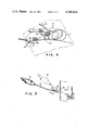
- FIG. 3 is a side view, partially in section, of the transducer probe
- FIG. 4 is a top view, partly in section, of the transducer probe disposed in contact with a turbine blade
- FIG. 5 is a view showing how the transducer probe assembly is manipulated through an aperture for contact with a turbine blade.
- a transducer probe 10 comprising an elongated molded body 11 which includes imbedded therein a piezoelectric element 12 adapted to be energized with high frequency electrical energy by means of electrical conductors 14 and 16 forming a cable 18.
- the molded body 11 typically comprises suitable epoxy material and it will be noted that the piezoelectric element 12 (transducer) is recessed in order that the molded plastic material 20 in front of the piezoelectric element 12 forms a so-called ultrasonic delay line for the ultrasonic energy before the ultrasonic energy enters the workpiece surface.
- the delay line permits near-surface inspection as is well known to those skilled in the art.
- the piezoelectric element 12 is so positioned within the molded body that the ultrasonic energy is transmitted along a predetermined beam axis 22 into the workpiece area to be tested.
- Damping material 23 the well known mixture of tungsten powder and epoxy, is disposed within the molded body to the rear of the piezoelectric element 12 in order to provide the required mechanical damping of the piezoelectric element.
- the molded body 11 includes an indexing portion 24 which, as more clearly seen in FIG. 4, is a return portion to snugly fit around the left edge 26 of the turbine blade TB.
- This return portion 24, hook shaped, is reinforced by an imbedded wire 28 in order to prevent this return portion from breaking off.
- the workpiece engaging surface or surfaces 30 of the ultrasonic transducer probe in connection with the return 24 and the inside contour 32 of the molded body 11 are so configured as to precisely conform to the blade construction TB, FIG. 5, at the root of the blade TB in order to accurately transmit ultrasonic energy into the critical root area.
- the transducer body with its return portion which serves for accurately indexing the transducer probe, form a unitary body which is precisely molded with the piezoelectric element 12 accurately positioned within the unitary body.
- the body 11 may be molded by special moulds which have been made by impressions taken of the actual workpiece.
- the molded transducer probe body is mounted to a manipulator 40 which comprises a hand grip 42 from which extends a substantially rigid tubing 44 and a substantially rigid wire 46.
- the transducer probe is pivotally mounted to the wire 46 and tubing 44 by means of a pivoting mechanism generally identified by numeral 48 which includes a pivoting pin 50 extending through a bifurcated bracket mounted to the wire 46.
- the transducer body not only is capable of pivoting about the pin 50 but there is also provided a lateral play so that the transducer body becomes self-aligning against the workpiece surface when engagement pressure is applied to the probe 10 via the hand grip 42, tubing 44, wire 46 and the pivotal mounting means 48.
- a pull mechanism for causing the probe to rotate about pin 50 and become generally aligned with the wire 46, see FIG. 5, solid lines.
- the pull mechanism comprises a flexible wire 60 attached to the molded probe body at its return portion 24 and this flexible wire 60, in turn, is connected to a pull mechanism 62 which includes the knob 64 of the handgrip 42.
- the handgrip 42 contains an electrical connector 66 which is the terminal for the electrical conductor 18 providing electrical energy to the piezoelectric element 12 and receiving the echo responsive electrical signals.
- a metering device 70 in the form of a syringe for discharging liquid couplant through a flexible hose 72 which discharges the liquid couplant through an inclined passage 74 of the molded probe body into the contact area between the transducer probe and the workpiece TB.
- the discharge of couplant liquid is indicated by arrow 76, FIG. 3.
- the present invention deals with a transducer probe arrangement which is adapted to be fed through a narrow space and placed in contact with a workpiece exhibiting a complex surface contour.
- the transducer body is molded to conform precisely to such complex contour and, moreover, includes as an integral part of its construction an indexing portion which accurately permits the placing of the transducer body in predetermined relation with the workpiece for causing ultrasonic waves to be propagated into a predetermined test area.
- the indexing means which forms a part of the transducer body permits the accurate placement of the transducer probe and such placement can be felt at the manipulator by virtue of the rigid mechanical connection between the probe and the manipulator.
- the accurate positioning of the probe, aside from the precise contour of the molded transducer body, is assured by the pivoting arrangement 48, 50 which includes a limited amount of lateral play as is indicated by the arrow 49 in FIG. 4.
Abstract
Description
Claims (7)
Priority Applications (1)
| Application Number | Priority Date | Filing Date | Title |
|---|---|---|---|
| US06/236,888 US4368642A (en) | 1981-02-23 | 1981-02-23 | Ultrasonic transducer probe |
Applications Claiming Priority (1)
| Application Number | Priority Date | Filing Date | Title |
|---|---|---|---|
| US06/236,888 US4368642A (en) | 1981-02-23 | 1981-02-23 | Ultrasonic transducer probe |
Publications (1)
| Publication Number | Publication Date |
|---|---|
| US4368642A true US4368642A (en) | 1983-01-18 |
Family
ID=22891410
Family Applications (1)
| Application Number | Title | Priority Date | Filing Date |
|---|---|---|---|
| US06/236,888 Expired - Lifetime US4368642A (en) | 1981-02-23 | 1981-02-23 | Ultrasonic transducer probe |
Country Status (1)
| Country | Link |
|---|---|
| US (1) | US4368642A (en) |
Cited By (15)
| Publication number | Priority date | Publication date | Assignee | Title |
|---|---|---|---|---|
| EP0139317A2 (en) * | 1983-08-26 | 1985-05-02 | Dow Chemical (Nederland) B.V. | Apparatus and method for the non-destructive inspection of solid bodies |
| US4585608A (en) * | 1982-06-01 | 1986-04-29 | Brown Boveri Reaktor Gmbh | Device for the determination of the vibrations occurring at the internals of a reactor pressure vessel |
| US4741203A (en) * | 1986-11-21 | 1988-05-03 | Westinghouse Electric Corp. | Turbine inspection device and associated coil assembly and associated method |
| US4760876A (en) * | 1986-09-02 | 1988-08-02 | Westinghouse Electric Corp. | Remote inspection device transport system |
| US4763662A (en) * | 1985-06-07 | 1988-08-16 | Olympus Optical Co., Ltd. | Ultrasonic biopsy endoscope with extensible guide sheath |
| US4803563A (en) * | 1987-09-02 | 1989-02-07 | Westinghouse Electric Corp. | Rotor-in-stator examination magnetic carriage and positioning apparatus |
| US4811091A (en) * | 1987-09-02 | 1989-03-07 | Westinghouse Electric Corp. | Multi-directional mobile inspection system |
| US4889000A (en) * | 1987-02-11 | 1989-12-26 | Westinghouse Electric Corp. | Electric generator inspection system and motor controller |
| US4970890A (en) * | 1988-11-23 | 1990-11-20 | Westinghouse Electric Corp. | Electric generator inspection system |
| US5065635A (en) * | 1990-09-14 | 1991-11-19 | Westinghouse Electric Corp. | Apparatus and method for inspecting an item having grooves machined therein |
| WO1995025278A1 (en) * | 1994-03-17 | 1995-09-21 | Framatome | Non-destructive ultrasonic testing device for testing a cylindrical wall accessible through a narrow ring-shaped passage |
| US6508391B2 (en) | 2001-05-02 | 2003-01-21 | Patricia A. Gilbert | Medical storage pouch |
| US6698279B1 (en) | 1996-10-23 | 2004-03-02 | Ultrasonics And Magnetics Corporation | Method and apparatus for testing the integrity of railroad locomotive wheels and railroad car wheels |
| EP2650679A1 (en) * | 2012-04-13 | 2013-10-16 | Siemens Aktiengesellschaft | Device and method to perform ultrasonic testing of turbomachines |
| CN110441393A (en) * | 2019-07-31 | 2019-11-12 | 北京理工大学 | A kind of supersonic detection device and method |
Citations (5)
| Publication number | Priority date | Publication date | Assignee | Title |
|---|---|---|---|---|
| SU508736A1 (en) * | 1971-09-10 | 1976-03-30 | Ultrasonic flaw detection device | |
| DE2547472A1 (en) * | 1975-10-23 | 1977-04-28 | Interatom | Internal inspection of reactor vessel - using vertically movable arm pivotal about horizontal axis to sweep inner surface |
| US4194400A (en) * | 1977-12-21 | 1980-03-25 | General Electric Company | Ultrasonic inspection method |
| US4241609A (en) * | 1979-04-09 | 1980-12-30 | Standard Oil Company (Indiana) | Tube internal measuring instrument |
| US4306459A (en) * | 1980-02-15 | 1981-12-22 | Conoco Inc. | Transducer carrier for ultrasonic testing |
-
1981
- 1981-02-23 US US06/236,888 patent/US4368642A/en not_active Expired - Lifetime
Patent Citations (5)
| Publication number | Priority date | Publication date | Assignee | Title |
|---|---|---|---|---|
| SU508736A1 (en) * | 1971-09-10 | 1976-03-30 | Ultrasonic flaw detection device | |
| DE2547472A1 (en) * | 1975-10-23 | 1977-04-28 | Interatom | Internal inspection of reactor vessel - using vertically movable arm pivotal about horizontal axis to sweep inner surface |
| US4194400A (en) * | 1977-12-21 | 1980-03-25 | General Electric Company | Ultrasonic inspection method |
| US4241609A (en) * | 1979-04-09 | 1980-12-30 | Standard Oil Company (Indiana) | Tube internal measuring instrument |
| US4306459A (en) * | 1980-02-15 | 1981-12-22 | Conoco Inc. | Transducer carrier for ultrasonic testing |
Cited By (19)
| Publication number | Priority date | Publication date | Assignee | Title |
|---|---|---|---|---|
| US4585608A (en) * | 1982-06-01 | 1986-04-29 | Brown Boveri Reaktor Gmbh | Device for the determination of the vibrations occurring at the internals of a reactor pressure vessel |
| EP0139317A3 (en) * | 1983-08-26 | 1989-03-29 | Dow Chemical (Nederland) B.V. | Apparatus and method for the non-destructive inspection of solid bodies |
| EP0139317A2 (en) * | 1983-08-26 | 1985-05-02 | Dow Chemical (Nederland) B.V. | Apparatus and method for the non-destructive inspection of solid bodies |
| US4763662A (en) * | 1985-06-07 | 1988-08-16 | Olympus Optical Co., Ltd. | Ultrasonic biopsy endoscope with extensible guide sheath |
| US4760876A (en) * | 1986-09-02 | 1988-08-02 | Westinghouse Electric Corp. | Remote inspection device transport system |
| US4741203A (en) * | 1986-11-21 | 1988-05-03 | Westinghouse Electric Corp. | Turbine inspection device and associated coil assembly and associated method |
| US4889000A (en) * | 1987-02-11 | 1989-12-26 | Westinghouse Electric Corp. | Electric generator inspection system and motor controller |
| US4811091A (en) * | 1987-09-02 | 1989-03-07 | Westinghouse Electric Corp. | Multi-directional mobile inspection system |
| US4803563A (en) * | 1987-09-02 | 1989-02-07 | Westinghouse Electric Corp. | Rotor-in-stator examination magnetic carriage and positioning apparatus |
| US4970890A (en) * | 1988-11-23 | 1990-11-20 | Westinghouse Electric Corp. | Electric generator inspection system |
| US5065635A (en) * | 1990-09-14 | 1991-11-19 | Westinghouse Electric Corp. | Apparatus and method for inspecting an item having grooves machined therein |
| WO1995025278A1 (en) * | 1994-03-17 | 1995-09-21 | Framatome | Non-destructive ultrasonic testing device for testing a cylindrical wall accessible through a narrow ring-shaped passage |
| FR2717578A1 (en) * | 1994-03-17 | 1995-09-22 | Framatome Sa | Device for non-destructive ultrasonic testing of a cylindrical wall accessible by an annular passage of small width. |
| US5652387A (en) * | 1994-03-17 | 1997-07-29 | Framatome | Device for non-destructive ultrasonic testing of a cylindrical wall accessible through a narrow annular passage |
| US6698279B1 (en) | 1996-10-23 | 2004-03-02 | Ultrasonics And Magnetics Corporation | Method and apparatus for testing the integrity of railroad locomotive wheels and railroad car wheels |
| US6508391B2 (en) | 2001-05-02 | 2003-01-21 | Patricia A. Gilbert | Medical storage pouch |
| EP2650679A1 (en) * | 2012-04-13 | 2013-10-16 | Siemens Aktiengesellschaft | Device and method to perform ultrasonic testing of turbomachines |
| EP4019962A3 (en) * | 2012-04-13 | 2022-08-03 | Siemens Energy Global GmbH & Co. KG | Device and a method to perform ultrasonic testing of turbomachines |
| CN110441393A (en) * | 2019-07-31 | 2019-11-12 | 北京理工大学 | A kind of supersonic detection device and method |
Similar Documents
| Publication | Publication Date | Title |
|---|---|---|
| US4368642A (en) | Ultrasonic transducer probe | |
| US4398421A (en) | Ultrasonic thickness measuring apparatus and method | |
| US5691476A (en) | Method for ultrasonic imaging and device for performing the method | |
| US7450055B2 (en) | Coaxial connector in radar level gauge | |
| EP2132577B1 (en) | Method and apparatus for detecting contact of a pipetting needle with a liquid in a vessel | |
| US2787160A (en) | Ultrasonic liquid depth indicator | |
| EP0780664A3 (en) | Sensor apparatus for process measurement | |
| EP0615647A1 (en) | Acoustic non-destructive testing | |
| GB2298277A (en) | Delay line for an ultrasonic probe with an interface allowing inbuilt calibration | |
| GB1124898A (en) | Ultrasonic inspection method and apparatus | |
| US4445360A (en) | Method for ultrasonically determining characteristics of a body | |
| EP0839585A3 (en) | Method and apparatus for testing transducer horn assembly debubbling devices | |
| GB1142544A (en) | Single sonic conductor mechanical wave depth gauge for the measurement of liquid levels | |
| FR2476964A1 (en) | MECHANISM FOR SECTIONING AND REDUCING THE CONDUCTORS OF COMPONENTS OF PRINTED CIRCUIT BOARDS | |
| JPH0363512A (en) | Apparatus and method for detecting ice | |
| US5493912A (en) | Ultrasonic probe suitable for acoustic coupling via a water channel | |
| US5419195A (en) | Ultrasonic booted head probe for motor bore inspection | |
| DE3277518D1 (en) | Method of recording foetal movements during pregnancy, and apparatus therefor | |
| JPH022927A (en) | Method and apparatus for detecting acoustic reflection | |
| US3379902A (en) | Ultrasonic testing apparatus | |
| US4238963A (en) | Test head for ultrasonic testing of structural material | |
| KR20060004956A (en) | Systems and methods for non-contact measuring sputtering target thickness using ultrasonics | |
| US5406851A (en) | Ultrasonic transducer system | |
| JP2000338092A (en) | Method for ultrasonic inspection | |
| JPH09273922A (en) | Apparatus for measuring thickness |
Legal Events
| Date | Code | Title | Description |
|---|---|---|---|
| AS | Assignment |
Owner name: KRAUTKRAMER-BRANSON, INC., 250 LONG BEACH BLVD., S Free format text: ASSIGNMENT OF ASSIGNORS INTEREST.;ASSIGNOR:CARODISKEY, THOMAS J.;REEL/FRAME:003918/0721 Effective date: 19810212 |
|
| STCF | Information on status: patent grant |
Free format text: PATENTED CASE |
|
| MAFP | Maintenance fee payment |
Free format text: PAYMENT OF MAINTENANCE FEE, 4TH YEAR, PL 96-517 (ORIGINAL EVENT CODE: M170); ENTITY STATUS OF PATENT OWNER: LARGE ENTITY Year of fee payment: 4 |
|
| MAFP | Maintenance fee payment |
Free format text: PAYMENT OF MAINTENANCE FEE, 8TH YEAR, PL 96-517 (ORIGINAL EVENT CODE: M171); ENTITY STATUS OF PATENT OWNER: LARGE ENTITY Year of fee payment: 8 |
|
| MAFP | Maintenance fee payment |
Free format text: PAYMENT OF MAINTENANCE FEE, 12TH YEAR, LARGE ENTITY (ORIGINAL EVENT CODE: M185); ENTITY STATUS OF PATENT OWNER: LARGE ENTITY Year of fee payment: 12 |