US4370091A - Remote manipulator arm - Google Patents
Remote manipulator arm Download PDFInfo
- Publication number
- US4370091A US4370091A US06/170,239 US17023980A US4370091A US 4370091 A US4370091 A US 4370091A US 17023980 A US17023980 A US 17023980A US 4370091 A US4370091 A US 4370091A
- Authority
- US
- United States
- Prior art keywords
- arm
- component
- coupling
- manipulator
- moving
- Prior art date
- Legal status (The legal status is an assumption and is not a legal conclusion. Google has not performed a legal analysis and makes no representation as to the accuracy of the status listed.)
- Expired - Lifetime
Links
Images
Classifications
-
- B—PERFORMING OPERATIONS; TRANSPORTING
- B25—HAND TOOLS; PORTABLE POWER-DRIVEN TOOLS; MANIPULATORS
- B25J—MANIPULATORS; CHAMBERS PROVIDED WITH MANIPULATION DEVICES
- B25J19/00—Accessories fitted to manipulators, e.g. for monitoring, for viewing; Safety devices combined with or specially adapted for use in connection with manipulators
- B25J19/0025—Means for supplying energy to the end effector
- B25J19/0029—Means for supplying energy to the end effector arranged within the different robot elements
-
- B—PERFORMING OPERATIONS; TRANSPORTING
- B23—MACHINE TOOLS; METAL-WORKING NOT OTHERWISE PROVIDED FOR
- B23Q—DETAILS, COMPONENTS, OR ACCESSORIES FOR MACHINE TOOLS, e.g. ARRANGEMENTS FOR COPYING OR CONTROLLING; MACHINE TOOLS IN GENERAL CHARACTERISED BY THE CONSTRUCTION OF PARTICULAR DETAILS OR COMPONENTS; COMBINATIONS OR ASSOCIATIONS OF METAL-WORKING MACHINES, NOT DIRECTED TO A PARTICULAR RESULT
- B23Q1/00—Members which are comprised in the general build-up of a form of machine, particularly relatively large fixed members
- B23Q1/25—Movable or adjustable work or tool supports
- B23Q1/44—Movable or adjustable work or tool supports using particular mechanisms
- B23Q1/50—Movable or adjustable work or tool supports using particular mechanisms with rotating pairs only, the rotating pairs being the first two elements of the mechanism
- B23Q1/54—Movable or adjustable work or tool supports using particular mechanisms with rotating pairs only, the rotating pairs being the first two elements of the mechanism two rotating pairs only
- B23Q1/5468—Movable or adjustable work or tool supports using particular mechanisms with rotating pairs only, the rotating pairs being the first two elements of the mechanism two rotating pairs only a single rotating pair followed parallelly by a single rotating pair
- B23Q1/5481—Movable or adjustable work or tool supports using particular mechanisms with rotating pairs only, the rotating pairs being the first two elements of the mechanism two rotating pairs only a single rotating pair followed parallelly by a single rotating pair followed parallelly by a single rotating pair
-
- B—PERFORMING OPERATIONS; TRANSPORTING
- B25—HAND TOOLS; PORTABLE POWER-DRIVEN TOOLS; MANIPULATORS
- B25J—MANIPULATORS; CHAMBERS PROVIDED WITH MANIPULATION DEVICES
- B25J15/00—Gripping heads and other end effectors
- B25J15/0052—Gripping heads and other end effectors multiple gripper units or multiple end effectors
-
- B—PERFORMING OPERATIONS; TRANSPORTING
- B25—HAND TOOLS; PORTABLE POWER-DRIVEN TOOLS; MANIPULATORS
- B25J—MANIPULATORS; CHAMBERS PROVIDED WITH MANIPULATION DEVICES
- B25J9/00—Programme-controlled manipulators
- B25J9/0009—Constructional details, e.g. manipulator supports, bases
- B25J9/0018—Bases fixed on ceiling, i.e. upside down manipulators
-
- B—PERFORMING OPERATIONS; TRANSPORTING
- B25—HAND TOOLS; PORTABLE POWER-DRIVEN TOOLS; MANIPULATORS
- B25J—MANIPULATORS; CHAMBERS PROVIDED WITH MANIPULATION DEVICES
- B25J9/00—Programme-controlled manipulators
- B25J9/02—Programme-controlled manipulators characterised by movement of the arms, e.g. cartesian coordinate type
- B25J9/04—Programme-controlled manipulators characterised by movement of the arms, e.g. cartesian coordinate type by rotating at least one arm, excluding the head movement itself, e.g. cylindrical coordinate type or polar coordinate type
-
- B—PERFORMING OPERATIONS; TRANSPORTING
- B25—HAND TOOLS; PORTABLE POWER-DRIVEN TOOLS; MANIPULATORS
- B25J—MANIPULATORS; CHAMBERS PROVIDED WITH MANIPULATION DEVICES
- B25J9/00—Programme-controlled manipulators
- B25J9/08—Programme-controlled manipulators characterised by modular constructions
Definitions
- the invention relates to a remote manipulator arm of the type comprising an articulated assembly connecting a manipulator to a support, the said articulated assembly being built up from standard independent components interconnected by articulations capable of transmitting independent movements in order to achieve a predetermined movement of the said manipulator with respect to the said support.
- Such manipulator arms are described in French Pat. No. 1 459 250, and the inventor of the present invention is named as one of the inventors therein.
- manipulator arms One of the most important applications of such manipulator arms is in providing remote power manipulators for laboratories using highly radioactive materials.
- the radioactive environment imposes many constraints on the design of manipulator arms affecting both their design and their performance.
- users seek as many degrees of freedom, as many relative configurations, and as great a capacity as possible for load bearing and/or reach. Nonetheless, it is necessary that such performance does not lead to excessive increase of the radial extent and the weight of the assembly, since these parameters are also important.
- Preferred embodiments of the present invention improve the design of prior manipulator arms by improving their load performance and reducing their radial extent, while retaining the other advantages of the prior art. These designs seek to combine as far as possible the advantages of arms comprising a linkage of two standard arm components with those of arms comprising a linkage of three standard arm components.
- the present invention provides a remote manipulator arm comprising an articulated assembly connecting a manipulator to a support.
- the articulated assembly built up from a plurality of independently motorized arm components each of which comprises at least one motor and an elongate body equipped with an axially-directed fixed coupling at one end with a moving portion at its other end.
- the moving portion is caused to move relative to the body under the control of said at least one motor, and is constituted, in the case of an end component, by said manipulator, and in the case of any other arm component by a moving coupling for connection to the fixed coupling of an adjacent arm component.
- the support is equipped with a moving coupling for connection to the fixed coupling of the first arm component of the articulated assembly.
- At least one of said arm components also includes at least one intermediate fixed coupling located on the side of the body between its ends and directed at 90° to the axis of the body.
- the intermediate fixed coupling is interchangeably useable with the end fixed coupling for connection to a moving coupling, thereby providing an arm component capable of being arranged in the articulated arm assembly in at least two different configurations relative to the moving coupling to which it is connected.
- the manipulator arm provides at least one of the following features.
- At least one of the arm components has two intermediate couplings arranged about mutually perpendicular axes, thereby providing two types of rigid sideways connection at one of two desired relative angular positions between the components connected thereby.
- At least one of the arm components includes an intermediate coupling unit fixed on a girth ring arranged around the body of the component and capable of rotating thereabout. Rotation of the said girth ring about the longitudinal axis of the said component provides multiple configurations of rigid sideways coupling depending on the angular position of the girth ring.
- the second arm component For an arm comprising three arm components of which the first arm component is connected to a support, the second arm component includes an intermediate coupling and the third arm component is an end component bearing a manipulator.
- the coupling between the first and second arm components is a rigid sideways connection at 90° providing by the intermediate coupling on the second arm component, while the couplings between the support and the first component, and between the second component and the third component are in a conventional end-to-end configuration.
- the invention also provides an arm component including an intermediate fixed coupling as defined above in relation to the arm assembly as a whole.
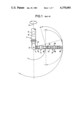
- FIG. 1 is a diagrammatic elevation of a prior art manipulator arm having two standard arm components.
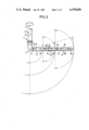
- FIG. 2 is a diagrammatic elevation of a manipulator arm in accordance with the invention, having three standard arm components including one intermediate arm component of special design, but with the arm arranged in a conventional in-line configuration.
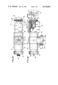
- FIGS. 3A and 3B are two partially cut-away views on a larger scale showing details of the design of the special intermediate arm of the FIG. 2.
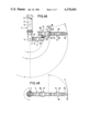
- FIGS. 4A and 4B are an elevation and a plan view respectively, of the manipulator arm of FIG. 2 assembled in a completely novel right-angle configuration.
- FIG. 5 is a partially cut-away view on a larger scale showing details of a variant design for the intermediate arm component, which in this case has two sideways coupling units.
- FIGS. 6A and 6B are an elevation and a plan view respectively of a manipulator arm including the intermediate arm component having two sideways couplings as shown in FIG. 5, in one of its two possible right-angled configurations.
- FIG. 7A is a partially cut-away view on a larger scale showing a further design variant of the intermediate arm component, which in this case includes a moving girth ring to which a single sideways coupling unit is fastened
- FIG. 7B is an end view along an arrow F of the component shown in FIG. 7A.
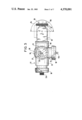
- FIG. 1 shows a conventional remote manipulator arm with two arm components. It comprises a support component 1 which is disposed vertically in use and is arranged to rotate about its axis 2. The lower end of the support component 1 comprises a shoulder 3 with an articulated coupling portion 4 for connection to the following arm component.
- the support component 1 includes a motor represented at 5 for controlling its rotation about the vertical axis 2 and a motor outlined at 6 for controlling rotation of the coupling portion 4, and hence of the remainder of the arm downstream therefrom.
- a standard and independent basic component 7 is connected to the coupling portion 4 of the support component by a ring nut 8.
- the basic component is independent in that it includes a motor 9 controlling the rotation of its own downstream end in a fork 10, thus controlling rotation of the remainder of the arm downstream from the fork.
- the following component is a manipulator component 11 in this case, but could alternatively be a further basic arm component identical to the basic component 7 to provide an arm having three arm components.
- the component 11 is likewise standard and independent and is connected to the articulated portion of the preceding arm component by a ring nut 12. At its free end there is a manipulator, in this case a pincer tool 13.
- the manipulator component 11 is independent in the sense that it includes a motor 14 controlling rotation of the tool 13 about the axis of the component, a motor 15 controlling opening and closing of the tool, and a motor 16 controlling telescopic extension and retraction of the tool.
- the couplings between the arm components in addition to providing mechanical connection, also provide pneumatic and/or electrical connection enabling overall control of the manipulator arm movements from outside a sealed work enclosure.
- Such arms are already in use and generally have a load capacity of about 100 kg for a two component arm and 50 kg for a three component arm. Further, articulated movement is only possible in vertical planes, as shown in FIG. 1 by faint lines.
- the aim of the invention is to improve capabilities of the arm shown in FIG. 1 by providing at least one arm component of special design.
- At least one of the components is provided with at least one intermediate coupling for providing a rigid 90° side coupling with the end of another component adjacent thereto.
- the said intermediate coupling provides the same capabilities of relative movement between components connected thereby as does an end coupling.
- a manipulator arm in accordance with the invention comprises a support component 1, a basic component 7 and a manipulator component 11 that are identical to those described with reference to FIG. 1.
- it also includes an intermediate basic component 17 of special design.
- the intermediate basic component 17 in addition to an upstream ring nut 18, a downstream coupling fork 19, and an independent motor 20 controlling rotation of the downstream arm component, the intermediate basic component 17 also includes an intermediate unit 21 for providing a rigid side coupling at 90°.
- the in-line assembly shown in FIG. 2 is entirely conventional, and merely serves to illustrate the possibility of including an intermediate component 17 in an end-to-end arrangement of an existing installation. Naturally the assembly shown in FIG. 2 does not offer the advantages mentioned below that can be obtained using a right-angled configuration.
- the arm assembly shown in FIG. 2 is capable of articulated motion only in vertical plane.
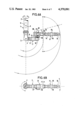
- the intermediate arm component 17 is shown in greater detail in FIGS. 3A and 3B. It essentially comprises a body 22 terminated at one end by the ring nut 18 and at the other by the coupling fork 19 in which a coupling portion 23 is articulated.
- the body houses a conventional motor reduction gearbox assembly including a friction-based mechanical torque limiter (providing long-life since it only operates when the predetermined torque is exceeded).
- the motor/gearing assembly also includes such means to enable the arm to go limp for extraction from the work chamber in the event of a breakdown.
- control is by way of electrical connection only (which is more economical from the point of view of energy consumption) and the connection is by way of male connectors 124 (associated with the ring nut) and female connectors 125 (associated with the coupling fork).
- the mechanical coupling is very simple, and merely comprises screwing the nut over the corresponding threaded part 24 of the coupling portion 23, after initially engaging guide pins 26 in corresponding blind holes 27 followed by engaging the end 22A of the body 22 in a sealing ring 23A, with electrical connection being achieved simultaneously.
- the moving portion 23 is moved by the last gear wheel 25 of a gear chain in known manner.
- the body of the component 17 also has an intermediate coupling 21 provided with a ring nut 18 and a male electrical connector 124 in a manner similar to the end coupling, whereby a standard component can be directly connected thereto via its coupling fork, thereby obtaining a rigid sideways connection at 90°.
- a protective cap 28 may be provided over the coupling 21 while not in use, e.g. when assembled in an in-line arrangement. 29 points to a diagrammatic representation of the external outlet of the clutch device, which in this example is constituted by the torque limiter (not shown).
- FIGS. 4A and 4B illustrate a right-angled connection of an arm in accordance with the invention, as made possible by the intermediate coupling 21 provided on the arm component 17.
- the intermediate component 17 is free to move in a vertical plane relative to the basic component 7, while the manipulator component 11 is free to move in a horizontal plane about a vertical axis 30 relative to the intermediate component 17.
- This movement about the vertical axis 30, which was not obtainable with prior art manipulators, can be very useful in combination with rotation of the support 1 about its axis 2.
- the center of gravity of the arm component 17 is moved closer to the axis 2 than in the configuration of FIG. 2.
- the distance between the main articulation and the load in the pincer is reduced, thereby giving rise to greater lifting power, giving a three component arm practically the same lifting power as a prior two component arm.
- this configuration has the further advantage of avoiding direct loading of the articulation between the intermediate component and the manipulator component while loads are being transported, thereby further increasing the capability of the arm.
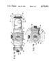
- FIG. 5 A component of this type is shown in FIG. 5.
- the body 22 now has two identical side coupling units 21, which are preferably at 90°.
- This component can either be assembled in a right-angled configuration as shown in FIGS. 4A and 4B to give two vertical articulations and one horizontal articulation, or else it can be assembled in the right angled configuration of FIGS. 6A and 6B giving three vertical articulations. In this latter configuration, all the articulation axes are again parallel, but nonetheless, since such an assembly is shorter than that shown in FIG. 2, it provides increased lifting capacity as in the case illustrated in the FIGS. 4A and 4B.
- the above principal can be further generalised, providing more options for arm assembly, by providing an intermediate component with a side coupling unit mounted on a girth ring around the components and capable of rotating thereabout. It is thus possible to provide a rigid side connection at any desired angle about the longitudinal axes of the intermediate component.
- a component 32 of this type is shown in FIGS. 7A and 7B.
- the body 22 is surrounded by a moving girth ring 33 to which a side coupling unit 21 of the type described above is fastened.
- the angular position of the coupling unit relative to the body can be set by an external member 34, whereby a plurality of intermediate positions can be devised using a single coupling unit (clearly sufficient slack will have to be provided for the electrical connections to ensure that rotation over a useful angle, e.g. 90°, is possible).
- the manipulator arm in accordance with the invention should naturally be provided with various safety devices to overcome different kinds of breakdown and loss of use of some component at whatever level along the arm it may occur.
- These safety devices are conventional and well-known to the person in the art.
- any kind of power supply can be chosen, for example: pneumatic, electrical, hydraulic, or even a mixture thereof (say electrical for all movements other than pincer movement and pneumatic for the pincer).
Abstract
A remote manipulator arm interconnects a manipulator tool (13) to a support (1). The arm comprises three independent motorized arm components (7,17 and 11). Conventional arm components are arranged for end-to-end coupling with a fixed end coupling at one end and articulated coupling disposed in a fork (10) at the other end. The present invention provides at least one intermediate component (17) which further includes at least one fixed coupling (21) arranged at 90° to its end coupling. Such a right-angled component provides greater flexibility in the design of a remote manipulator arm assembled from such components.
Description
The invention relates to a remote manipulator arm of the type comprising an articulated assembly connecting a manipulator to a support, the said articulated assembly being built up from standard independent components interconnected by articulations capable of transmitting independent movements in order to achieve a predetermined movement of the said manipulator with respect to the said support. Such manipulator arms are described in French Pat. No. 1 459 250, and the inventor of the present invention is named as one of the inventors therein.
One of the most important applications of such manipulator arms is in providing remote power manipulators for laboratories using highly radioactive materials. The radioactive environment imposes many constraints on the design of manipulator arms affecting both their design and their performance. In particular, users seek as many degrees of freedom, as many relative configurations, and as great a capacity as possible for load bearing and/or reach. Nonetheless, it is necessary that such performance does not lead to excessive increase of the radial extent and the weight of the assembly, since these parameters are also important.
Preferred embodiments of the present invention improve the design of prior manipulator arms by improving their load performance and reducing their radial extent, while retaining the other advantages of the prior art. These designs seek to combine as far as possible the advantages of arms comprising a linkage of two standard arm components with those of arms comprising a linkage of three standard arm components.
The present invention provides a remote manipulator arm comprising an articulated assembly connecting a manipulator to a support. The articulated assembly built up from a plurality of independently motorized arm components each of which comprises at least one motor and an elongate body equipped with an axially-directed fixed coupling at one end with a moving portion at its other end. The moving portion is caused to move relative to the body under the control of said at least one motor, and is constituted, in the case of an end component, by said manipulator, and in the case of any other arm component by a moving coupling for connection to the fixed coupling of an adjacent arm component. The support is equipped with a moving coupling for connection to the fixed coupling of the first arm component of the articulated assembly. At least one of said arm components also includes at least one intermediate fixed coupling located on the side of the body between its ends and directed at 90° to the axis of the body. The intermediate fixed coupling is interchangeably useable with the end fixed coupling for connection to a moving coupling, thereby providing an arm component capable of being arranged in the articulated arm assembly in at least two different configurations relative to the moving coupling to which it is connected.
Preferably, the manipulator arm provides at least one of the following features.
At least one of the arm components has two intermediate couplings arranged about mutually perpendicular axes, thereby providing two types of rigid sideways connection at one of two desired relative angular positions between the components connected thereby.
At least one of the arm components includes an intermediate coupling unit fixed on a girth ring arranged around the body of the component and capable of rotating thereabout. Rotation of the said girth ring about the longitudinal axis of the said component provides multiple configurations of rigid sideways coupling depending on the angular position of the girth ring.
For an arm comprising three arm components of which the first arm component is connected to a support, the second arm component includes an intermediate coupling and the third arm component is an end component bearing a manipulator. The coupling between the first and second arm components is a rigid sideways connection at 90° providing by the intermediate coupling on the second arm component, while the couplings between the support and the first component, and between the second component and the third component are in a conventional end-to-end configuration.
The invention also provides an arm component including an intermediate fixed coupling as defined above in relation to the arm assembly as a whole.
Other characteristics and advantages of the invention will appear more clearly from the following description given by way of example of no limiting character with reference to the accompanying drawings.
FIG. 1 is a diagrammatic elevation of a prior art manipulator arm having two standard arm components.
FIG. 2 is a diagrammatic elevation of a manipulator arm in accordance with the invention, having three standard arm components including one intermediate arm component of special design, but with the arm arranged in a conventional in-line configuration.
FIGS. 3A and 3B are two partially cut-away views on a larger scale showing details of the design of the special intermediate arm of the FIG. 2.
FIGS. 4A and 4B are an elevation and a plan view respectively, of the manipulator arm of FIG. 2 assembled in a completely novel right-angle configuration.
FIG. 5 is a partially cut-away view on a larger scale showing details of a variant design for the intermediate arm component, which in this case has two sideways coupling units.
FIGS. 6A and 6B are an elevation and a plan view respectively of a manipulator arm including the intermediate arm component having two sideways couplings as shown in FIG. 5, in one of its two possible right-angled configurations.
FIG. 7A is a partially cut-away view on a larger scale showing a further design variant of the intermediate arm component, which in this case includes a moving girth ring to which a single sideways coupling unit is fastened, and FIG. 7B is an end view along an arrow F of the component shown in FIG. 7A.
FIG. 1 shows a conventional remote manipulator arm with two arm components. It comprises a support component 1 which is disposed vertically in use and is arranged to rotate about its axis 2. The lower end of the support component 1 comprises a shoulder 3 with an articulated coupling portion 4 for connection to the following arm component. The support component 1 includes a motor represented at 5 for controlling its rotation about the vertical axis 2 and a motor outlined at 6 for controlling rotation of the coupling portion 4, and hence of the remainder of the arm downstream therefrom. A standard and independent basic component 7 is connected to the coupling portion 4 of the support component by a ring nut 8. The basic component is independent in that it includes a motor 9 controlling the rotation of its own downstream end in a fork 10, thus controlling rotation of the remainder of the arm downstream from the fork. The following component is a manipulator component 11 in this case, but could alternatively be a further basic arm component identical to the basic component 7 to provide an arm having three arm components. The component 11 is likewise standard and independent and is connected to the articulated portion of the preceding arm component by a ring nut 12. At its free end there is a manipulator, in this case a pincer tool 13. The manipulator component 11 is independent in the sense that it includes a motor 14 controlling rotation of the tool 13 about the axis of the component, a motor 15 controlling opening and closing of the tool, and a motor 16 controlling telescopic extension and retraction of the tool. The couplings between the arm components, in addition to providing mechanical connection, also provide pneumatic and/or electrical connection enabling overall control of the manipulator arm movements from outside a sealed work enclosure.
Such arms are already in use and generally have a load capacity of about 100 kg for a two component arm and 50 kg for a three component arm. Further, articulated movement is only possible in vertical planes, as shown in FIG. 1 by faint lines.
The aim of the invention is to improve capabilities of the arm shown in FIG. 1 by providing at least one arm component of special design.
In accordance with the invention, at least one of the components is provided with at least one intermediate coupling for providing a rigid 90° side coupling with the end of another component adjacent thereto. The said intermediate coupling provides the same capabilities of relative movement between components connected thereby as does an end coupling. This design thus makes it possible to vary the number of components and their relative disposition in such a manner as to obtain minimum bulk and to obtain different arrangements of articulation axis with respect to each other depending on the desired end use. Further, by reducing the overall bulk and by balancing the moving masses, it is possible to improve the lifting performance by using a more compact arrangement since the intermediate coupling shortens the lever arm, thereby providing greater flexibility in dealing with a wide range of problems.
In FIG. 2 a manipulator arm in accordance with the invention comprises a support component 1, a basic component 7 and a manipulator component 11 that are identical to those described with reference to FIG. 1. However, it also includes an intermediate basic component 17 of special design. Thus, in addition to an upstream ring nut 18, a downstream coupling fork 19, and an independent motor 20 controlling rotation of the downstream arm component, the intermediate basic component 17 also includes an intermediate unit 21 for providing a rigid side coupling at 90°. The in-line assembly shown in FIG. 2 is entirely conventional, and merely serves to illustrate the possibility of including an intermediate component 17 in an end-to-end arrangement of an existing installation. Naturally the assembly shown in FIG. 2 does not offer the advantages mentioned below that can be obtained using a right-angled configuration.
In particular it should be noted that as for the conventional arm, the arm assembly shown in FIG. 2 is capable of articulated motion only in vertical plane.
The intermediate arm component 17 is shown in greater detail in FIGS. 3A and 3B. It essentially comprises a body 22 terminated at one end by the ring nut 18 and at the other by the coupling fork 19 in which a coupling portion 23 is articulated. The body houses a conventional motor reduction gearbox assembly including a friction-based mechanical torque limiter (providing long-life since it only operates when the predetermined torque is exceeded). The motor/gearing assembly also includes such means to enable the arm to go limp for extraction from the work chamber in the event of a breakdown. In this example, control is by way of electrical connection only (which is more economical from the point of view of energy consumption) and the connection is by way of male connectors 124 (associated with the ring nut) and female connectors 125 (associated with the coupling fork). The mechanical coupling is very simple, and merely comprises screwing the nut over the corresponding threaded part 24 of the coupling portion 23, after initially engaging guide pins 26 in corresponding blind holes 27 followed by engaging the end 22A of the body 22 in a sealing ring 23A, with electrical connection being achieved simultaneously. The moving portion 23 is moved by the last gear wheel 25 of a gear chain in known manner. In accordance with the invention the body of the component 17 also has an intermediate coupling 21 provided with a ring nut 18 and a male electrical connector 124 in a manner similar to the end coupling, whereby a standard component can be directly connected thereto via its coupling fork, thereby obtaining a rigid sideways connection at 90°. A protective cap 28 may be provided over the coupling 21 while not in use, e.g. when assembled in an in-line arrangement. 29 points to a diagrammatic representation of the external outlet of the clutch device, which in this example is constituted by the torque limiter (not shown).
FIGS. 4A and 4B illustrate a right-angled connection of an arm in accordance with the invention, as made possible by the intermediate coupling 21 provided on the arm component 17. The intermediate component 17 is free to move in a vertical plane relative to the basic component 7, while the manipulator component 11 is free to move in a horizontal plane about a vertical axis 30 relative to the intermediate component 17. This movement about the vertical axis 30, which was not obtainable with prior art manipulators, can be very useful in combination with rotation of the support 1 about its axis 2. Further, the center of gravity of the arm component 17 is moved closer to the axis 2 than in the configuration of FIG. 2. Thus the distance between the main articulation and the load in the pincer is reduced, thereby giving rise to greater lifting power, giving a three component arm practically the same lifting power as a prior two component arm.
It should also be observed that this configuration has the further advantage of avoiding direct loading of the articulation between the intermediate component and the manipulator component while loads are being transported, thereby further increasing the capability of the arm.
The principal that has just been described can be improved by providing an intermediate component with two intermediate coupling units, about mutually perpendicular axes. This makes it possible to assemble two types of rigid side coupling depending on the desired relative angular positions of the components thus connected. A component of this type is shown in FIG. 5. The body 22 now has two identical side coupling units 21, which are preferably at 90°. This component can either be assembled in a right-angled configuration as shown in FIGS. 4A and 4B to give two vertical articulations and one horizontal articulation, or else it can be assembled in the right angled configuration of FIGS. 6A and 6B giving three vertical articulations. In this latter configuration, all the articulation axes are again parallel, but nonetheless, since such an assembly is shorter than that shown in FIG. 2, it provides increased lifting capacity as in the case illustrated in the FIGS. 4A and 4B.
The above principal can be further generalised, providing more options for arm assembly, by providing an intermediate component with a side coupling unit mounted on a girth ring around the components and capable of rotating thereabout. It is thus possible to provide a rigid side connection at any desired angle about the longitudinal axes of the intermediate component. A component 32 of this type is shown in FIGS. 7A and 7B. The body 22 is surrounded by a moving girth ring 33 to which a side coupling unit 21 of the type described above is fastened. The angular position of the coupling unit relative to the body can be set by an external member 34, whereby a plurality of intermediate positions can be devised using a single coupling unit (clearly sufficient slack will have to be provided for the electrical connections to ensure that rotation over a useful angle, e.g. 90°, is possible).
The manipulator arm in accordance with the invention should naturally be provided with various safety devices to overcome different kinds of breakdown and loss of use of some component at whatever level along the arm it may occur. These safety devices are conventional and well-known to the person in the art. Likewise any kind of power supply can be chosen, for example: pneumatic, electrical, hydraulic, or even a mixture thereof (say electrical for all movements other than pincer movement and pneumatic for the pincer).
Claims (5)
1. A remote manipulator arm comprising an articulated assembly connecting a manipulator to a support, said articulated assembly being built up from a plurality of independently motorized arm components each of which comprises at least one motor and an elongate body equipped with an axially-directed fixed coupling at one end and with a moving portion at its other end, said moving portion being caused to move relative to the body under the control of said at least one motor, and being constituted, in the case of an end component, by said manipulator, and in the case of any other arm component by a moving coupling for connection to the fixed coupling of an adjacent arm component, said support being equipped with a moving coupling for connection to the fixed coupling of the first arm component of the articulated assembly; the improvement wherein at least one of said arm components further comprises at least one intermediate fixed coupling located on the side of its body between its ends and directed at 90° to the axis of the body, said intermediate fixed coupling being identical to the axially directed fixed coupling of said one arm component interchangeably useable with the fixed end coupling connection to a moving coupling of another arm component thereby providing an arm component capable of being arranged in the articulated arm assembly in at least two different configurations relative to the moving coupling to which it is connected reducing the distance between the main articulation and the load borne by the manipulator thereby giving rise to a greater lifting power and providing a three component arm with practically the same lifting power as prior two component arms.
2. An arm according to claim 1, wherein said at least one arm component has two intermediate couplings arranged about mutually perpendicular axes, thereby providing two types of rigid sideways connection at one of two desired relative angular positions between the components connected thereby.
3. An arm according to claim 1, wherein said at least one arm component includes a girth ring arranged around the body of the component and capable of rotating thereabout, an intermediate coupling unit fixed on said girth ring, and means for rotating said girth ring about the longitudinal axis of said component providing multiple configurations of rigid sideways coupling depending on the angular position of said girth ring.
4. An arm according to claim 1, wherein said arm components comprise three in number and wherein the first arm component is connected to a support, the second arm component includes an intermediate coupling and the third arm component is an end component bearing a manipulator and wherein the coupling between the first and second arm components is a rigid sideways connection at 90° provided by the intermediate coupling on the second arm component, while the couplings between the support and the first component, and between the second component and the third component are in a conventional end-to-end configuration.
5. An arm component for use in a remote manipulator arm according to claim 1 or claim 4, wherein said arm component comprises a motor and an elongate body equipped with an axially-directed fixed coupling at one end, with a moving coupling at its other end, said moving coupling being caused to move relative to the body under the control of said motor, and with an intermediate fixed coupling located on the side of the body between its ends and directed at 90° to the axis of the body, said intermediate fixed coupling being interchangeably useable with an end fixed coupling for connection to a moving coupling on a different member.
Applications Claiming Priority (2)
| Application Number | Priority Date | Filing Date | Title |
|---|---|---|---|
| FR7918646A FR2461556A1 (en) | 1979-07-18 | 1979-07-18 | REMOTE HANDLING ARM |
| FR7918646 | 1979-07-18 |
Publications (1)
| Publication Number | Publication Date |
|---|---|
| US4370091A true US4370091A (en) | 1983-01-25 |
Family
ID=9228044
Family Applications (1)
| Application Number | Title | Priority Date | Filing Date |
|---|---|---|---|
| US06/170,239 Expired - Lifetime US4370091A (en) | 1979-07-18 | 1980-07-18 | Remote manipulator arm |
Country Status (7)
| Country | Link |
|---|---|
| US (1) | US4370091A (en) |
| JP (1) | JPS5615997A (en) |
| DE (1) | DE3026273A1 (en) |
| ES (1) | ES8105182A1 (en) |
| FR (1) | FR2461556A1 (en) |
| GB (1) | GB2053148B (en) |
| IT (1) | IT1128941B (en) |
Cited By (64)
| Publication number | Priority date | Publication date | Assignee | Title |
|---|---|---|---|---|
| US4527945A (en) * | 1981-09-15 | 1985-07-09 | Regie Nationale Des Usines Renault | Swivelling handle with three axes of rotation for an industrial robot |
| US4545723A (en) * | 1983-09-30 | 1985-10-08 | The United States Of America As Represented By The Administrator Of The National Aeronautics And Space Administration | Apparatus for adapting an end effector device remotely controlled manipulator arm |
| US4561506A (en) * | 1983-07-11 | 1985-12-31 | International Business Machines Corporation | Pivoting driver with changeable bits |
| US4585387A (en) * | 1983-10-11 | 1986-04-29 | William Jayne | Robot arm |
| US4585388A (en) * | 1984-05-08 | 1986-04-29 | Spar Aerospace Limited | Self-relocating manipulator |
| US4588346A (en) * | 1982-08-25 | 1986-05-13 | Intest Corporation | Positioner for maintaining an object in a substantially weightless condition |
| US4600355A (en) * | 1984-08-29 | 1986-07-15 | Cybot, Inc. | Modular robotics system with basic interchangeable parts |
| US4620362A (en) * | 1984-06-22 | 1986-11-04 | The Boeing Company | Changeable tooling system for robot end-effector |
| US4624043A (en) * | 1982-09-29 | 1986-11-25 | The Boeing Company | Quick release tool holder for robots |
| US4624621A (en) * | 1982-10-21 | 1986-11-25 | Kabushiki Kaisha Kobe Seiko Sho | Wrist mechanism for industrial robots and the like |
| US4636135A (en) * | 1983-03-11 | 1987-01-13 | Societe Syspro | Tool-holder for industrial robot |
| US4636138A (en) * | 1982-02-05 | 1987-01-13 | American Robot Corporation | Industrial robot |
| US4635985A (en) * | 1984-05-29 | 1987-01-13 | International Business Machines Corporation | Self-pivoting robotic gripper tool |
| US4645409A (en) * | 1982-02-05 | 1987-02-24 | American Cimflex Corporation | Outer arm assembly for industrial robot |
| US4647423A (en) * | 1983-08-26 | 1987-03-03 | The United States Of America As Represented By The United States Department Of Energy | Fuel handling apparatus for a nuclear reactor |
| US4650388A (en) * | 1982-09-20 | 1987-03-17 | La Calhene S.A. | Disconnectable coupling device for a manipulator wrist |
| US4664588A (en) * | 1984-03-09 | 1987-05-12 | Applied Robotics Inc. | Apparatus and method for connecting and exchanging remote manipulable elements to a central control source |
| US4684312A (en) * | 1984-04-30 | 1987-08-04 | Westinghouse Electric Corp. | Robotic wrist |
| US4705447A (en) * | 1983-08-11 | 1987-11-10 | Intest Corporation | Electronic test head positioner for test systems |
| US4716647A (en) * | 1985-09-17 | 1988-01-05 | Chiron-Werke Gmbh | Machine tool |
| US4762455A (en) * | 1987-06-01 | 1988-08-09 | Remote Technology Corporation | Remote manipulator |
| US4766775A (en) * | 1986-05-02 | 1988-08-30 | Hodge Steven W | Modular robot manipulator |
| US4778332A (en) * | 1987-02-09 | 1988-10-18 | The Perkin-Elmer Corporation | Wafer flip apparatus |
| US4780047A (en) * | 1985-04-05 | 1988-10-25 | Martin Marietta Energy Systems, Inc. | Advanced servo manipulator |
| US4815780A (en) * | 1987-03-30 | 1989-03-28 | Erowa Ag | Apparatus for detachably connecting a tool to a manipulating device |
| US4827954A (en) * | 1982-11-23 | 1989-05-09 | Interlab, Inc. | Automated work transfer system having an articulated arm |
| US4905938A (en) * | 1988-07-01 | 1990-03-06 | General Electric Company | Special purpose robotic end effector |
| US4921395A (en) * | 1982-04-16 | 1990-05-01 | Sahlin International, Inc. | Apparatus for loading and/or unloading industrial presses |
| US4973215A (en) * | 1986-02-18 | 1990-11-27 | Robotics Research Corporation | Industrial robot with servo |
| US5017083A (en) * | 1982-04-16 | 1991-05-21 | Sahlin International, Inc. | Apparatus for loading and/or unloading industrial presses |
| US5071309A (en) * | 1990-08-06 | 1991-12-10 | Syron Engineering & Manufacturing Corporation | Mounting arrangement for a multi-function arm |
| US5149029A (en) * | 1982-08-25 | 1992-09-22 | Intest Corporation | Electronic test head positioner for test systems |
| US5241875A (en) * | 1990-09-24 | 1993-09-07 | Uwe Kochanneck | Multiblock-robot |
| US5241870A (en) * | 1991-07-22 | 1993-09-07 | Intest Corporation | Test head manipulator |
| US5492443A (en) * | 1993-10-14 | 1996-02-20 | Leland D. Blatt | Apparatus for handling a workpiece between work stations |
| US5525027A (en) * | 1991-05-28 | 1996-06-11 | Kabushiki Kaisha Toshiba | Working robot |
| US5850762A (en) * | 1995-05-16 | 1998-12-22 | Kochanneck; Uwe | Multi-block robot |
| US6540188B2 (en) * | 2001-03-14 | 2003-04-01 | Syron Engineering & Manufacturing, L.L.C. | Mounting arrangement for multi-functional arm |
| US6685698B2 (en) | 2000-07-27 | 2004-02-03 | Intuitive Surgical, Inc. | Roll-pitch-roll surgical tool |
| US20040030395A1 (en) * | 2000-04-13 | 2004-02-12 | Gordon Blunn | Surgical distraction device |
| US20040053133A1 (en) * | 2001-11-09 | 2004-03-18 | Guohua Li | Positive plate material and cell comprising it |
| US6902560B1 (en) | 2000-07-27 | 2005-06-07 | Intuitive Surgical, Inc. | Roll-pitch-roll surgical tool |
| US20070059124A1 (en) * | 2005-08-25 | 2007-03-15 | Palo Alto Research Center Incorporated | Portable personal wearable active third arm |
| US20080042432A1 (en) * | 2006-07-04 | 2008-02-21 | Korea Atomic Energy Research Institute | Telescopic servomanipulator coupling/decoupling apparatus |
| US7366585B2 (en) | 2002-05-28 | 2008-04-29 | Kuka Roboter Gmbh | Method and apparatus for moving a handling system |
| US20090071281A1 (en) * | 2007-09-13 | 2009-03-19 | Fisk Allan T | Robot arm assembly |
| US20100101356A1 (en) * | 2008-10-24 | 2010-04-29 | Albin Scott R | Remotely controlled mobile robot in-line robot arm and end effector mechanism |
| US20100158656A1 (en) * | 2008-12-18 | 2010-06-24 | Seavey Nathaniel J M | Robot arm assembly |
| US20100164243A1 (en) * | 2008-12-29 | 2010-07-01 | Albin Scott R | Gripper system |
| US20110051877A1 (en) * | 2009-08-28 | 2011-03-03 | Searete Llc, A Limited Liability Corporation Of The State Of Delaware | Nuclear fission reactor, a vented nuclear fission fuel module, methods therefor and a vented nuclear fission fuel module system |
| US20110051881A1 (en) * | 2009-08-28 | 2011-03-03 | Searete Llc, A Limited Liability Corporation Of The State Of Delaware | Nuclear fission reactor, vented nuclear fission fuel module, methods therefor and a vented nuclear fission fuel module system |
| US20110058638A1 (en) * | 2009-08-28 | 2011-03-10 | Searete Llc, A Limited Liability Corporation Of The State Of Delaware | Nuclear fission reactor, a vented nuclear fission fuel module, methods therefor and a vented nuclear fission fuel module system |
| US20110088307A1 (en) * | 2009-10-20 | 2011-04-21 | Jason Todd Rice | Animated bird decoy and associated methods |
| US20110150167A1 (en) * | 2009-08-28 | 2011-06-23 | Searete Llc, A Limited Liability Corporation Of The State Of Delaware | Nuclear fission reactor, a vented nuclear fission fuel module, methods therefor and a vented nuclear fission fuel module system |
| US8414043B2 (en) | 2008-10-21 | 2013-04-09 | Foster-Miller, Inc. | End effector for mobile remotely controlled robot |
| US8488734B2 (en) | 2009-08-28 | 2013-07-16 | The Invention Science Fund I, Llc | Nuclear fission reactor, a vented nuclear fission fuel module, methods therefor and a vented nuclear fission fuel module system |
| CN103862464A (en) * | 2012-12-13 | 2014-06-18 | 库卡罗伯特有限公司 | Robot arm |
| US9033998B1 (en) | 2010-05-13 | 2015-05-19 | Titan Medical Inc. | Independent roll wrist mechanism |
| CN105014663A (en) * | 2015-08-26 | 2015-11-04 | 北京航空航天大学 | Base-loaded modular mechanical arm capable of realizing multi-directional connection |
| US20190383109A1 (en) * | 2018-06-15 | 2019-12-19 | Rus-Tec Engineering, Ltd. | Pipe Handling Apparatus |
| US10786897B2 (en) | 2016-03-08 | 2020-09-29 | Igus Gmbh | Robot arm |
| DE102019120128A1 (en) * | 2019-07-25 | 2021-01-28 | Beckhoff Automation Gmbh | Arm module, robotic arm and industrial robot |
| US11389970B2 (en) * | 2017-08-02 | 2022-07-19 | Hanwha Defense Co., Ltd. | Tool adapter for manipulating commercial tools with a robot hand |
| EP4023399A4 (en) * | 2019-08-29 | 2022-08-31 | Rethink Robotics GmbH | Connection assembly for robot joints |
Families Citing this family (22)
| Publication number | Priority date | Publication date | Assignee | Title |
|---|---|---|---|---|
| JPS584388A (en) * | 1981-06-30 | 1983-01-11 | ファナック株式会社 | Wrist mechanism of industrial robot |
| DE3275636D1 (en) * | 1981-11-11 | 1987-04-16 | Robotic Syst Ltd | Modular robot arm |
| FR2519284A1 (en) * | 1982-01-07 | 1983-07-08 | Bretagne Atel Chantiers | TELEMANIPULATOR |
| EP0102082B1 (en) * | 1982-08-30 | 1987-05-20 | Hitachi, Ltd. | Industrial robot |
| GB2126559A (en) * | 1982-09-07 | 1984-03-28 | Itt | Manipulator apparatus |
| EP0108657B1 (en) * | 1982-09-25 | 1987-08-12 | Fujitsu Limited | A multi-articulated robot |
| FR2539346B1 (en) * | 1983-01-18 | 1990-12-07 | Mitsubishi Electric Corp | ARTICULATED AUTOMATIC MANIPULATOR DEVICE, PARTICULARLY FOR ARC WELDING |
| US4550867A (en) * | 1983-10-14 | 1985-11-05 | National Steel Corporation | Shroud tube manipulating and supporting apparatus |
| CA1245244A (en) * | 1984-04-30 | 1988-11-22 | Richard S. Antoszewski | Robotic wrist |
| US4702668A (en) * | 1985-01-24 | 1987-10-27 | Adept Technology, Inc. | Direct drive robotic system |
| US4725965A (en) * | 1986-07-23 | 1988-02-16 | American Telephone And Telegraph Company | Method for calibrating a SCARA robot |
| DE3704951A1 (en) * | 1987-02-17 | 1988-08-25 | Fraunhofer Ges Forschung | Drive module for working joints of industrial robots |
| JPH01103275A (en) * | 1987-10-13 | 1989-04-20 | Honda Motor Co Ltd | Shaft structure of industrial robot |
| US5388946A (en) * | 1988-01-20 | 1995-02-14 | Grau Gmbh & Co. | Systems and methods for the automated archiving and retrieval of computer data storage cassettes |
| GB8811204D0 (en) * | 1988-05-11 | 1988-06-15 | Danzoe Eng Ltd | Improvements in/relating to support & manipulating apparatus |
| DE3918587A1 (en) * | 1988-06-13 | 1989-12-14 | Westinghouse Electric Corp | Reconfigurable articulated robot arm |
| DE4004738A1 (en) * | 1990-01-25 | 1991-08-08 | Maag Zahnraeder & Maschinen Ag | Manipulator module - has modular assembly for different movements and with power leads internal |
| DE59103288D1 (en) * | 1991-03-07 | 1994-11-24 | Thr Bilsing Gmbh | Automatic transport device, especially for transporting workpieces between presses. |
| EP0547421B1 (en) * | 1991-12-14 | 1996-08-21 | Uwe Kochanneck | Multiblock-Robot |
| JP5750029B2 (en) * | 2011-11-02 | 2015-07-15 | 本田技研工業株式会社 | Joint mechanism and work attachment |
| KR102230090B1 (en) | 2013-11-27 | 2021-03-19 | 디에보틱스 아이피, 엘엘씨 | Multiple axis work-piece transfer apparatus |
| CN105058421B (en) * | 2015-08-26 | 2017-01-18 | 北京航空航天大学 | Compact type mechanical arm joint module integrating two degrees of freedom |
Citations (5)
| Publication number | Priority date | Publication date | Assignee | Title |
|---|---|---|---|---|
| US2609638A (en) * | 1946-05-22 | 1952-09-09 | Ray S Lindenmeyer | Construction toy connector |
| US3155240A (en) * | 1960-02-16 | 1964-11-03 | Commissariat Energie Atomique | Remote manipulation apparatus |
| US4012153A (en) * | 1975-03-21 | 1977-03-15 | Pidgeon Martin J | Structural connection means |
| US4076429A (en) * | 1975-11-04 | 1978-02-28 | Kason Hardware Corporation | Convertible tube connecting system |
| US4089427A (en) * | 1975-09-22 | 1978-05-16 | Sofermo | Modular robot having an adaptable configuration |
Family Cites Families (2)
| Publication number | Priority date | Publication date | Assignee | Title |
|---|---|---|---|---|
| FR1459250A (en) * | 1965-10-06 | 1966-04-29 | Siersatom Sa | Remote manipulation arm |
| JPS5334268A (en) * | 1976-09-10 | 1978-03-30 | Nippon Denso Co Ltd | Wrists for industrial robot |
-
1979
- 1979-07-18 FR FR7918646A patent/FR2461556A1/en active Granted
-
1980
- 1980-07-11 DE DE19803026273 patent/DE3026273A1/en not_active Withdrawn
- 1980-07-14 GB GB8022910A patent/GB2053148B/en not_active Expired
- 1980-07-17 IT IT68145/80A patent/IT1128941B/en active
- 1980-07-17 ES ES493480A patent/ES8105182A1/en not_active Expired
- 1980-07-18 JP JP9927080A patent/JPS5615997A/en active Pending
- 1980-07-18 US US06/170,239 patent/US4370091A/en not_active Expired - Lifetime
Patent Citations (5)
| Publication number | Priority date | Publication date | Assignee | Title |
|---|---|---|---|---|
| US2609638A (en) * | 1946-05-22 | 1952-09-09 | Ray S Lindenmeyer | Construction toy connector |
| US3155240A (en) * | 1960-02-16 | 1964-11-03 | Commissariat Energie Atomique | Remote manipulation apparatus |
| US4012153A (en) * | 1975-03-21 | 1977-03-15 | Pidgeon Martin J | Structural connection means |
| US4089427A (en) * | 1975-09-22 | 1978-05-16 | Sofermo | Modular robot having an adaptable configuration |
| US4076429A (en) * | 1975-11-04 | 1978-02-28 | Kason Hardware Corporation | Convertible tube connecting system |
Cited By (89)
| Publication number | Priority date | Publication date | Assignee | Title |
|---|---|---|---|---|
| US4576544A (en) * | 1981-09-15 | 1986-03-18 | Regie Nationale Des Usines Renault | Swivelling handle with three axes of rotation for an industrial robot |
| US4527945A (en) * | 1981-09-15 | 1985-07-09 | Regie Nationale Des Usines Renault | Swivelling handle with three axes of rotation for an industrial robot |
| US4636138A (en) * | 1982-02-05 | 1987-01-13 | American Robot Corporation | Industrial robot |
| US4645409A (en) * | 1982-02-05 | 1987-02-24 | American Cimflex Corporation | Outer arm assembly for industrial robot |
| US4921395A (en) * | 1982-04-16 | 1990-05-01 | Sahlin International, Inc. | Apparatus for loading and/or unloading industrial presses |
| US5017083A (en) * | 1982-04-16 | 1991-05-21 | Sahlin International, Inc. | Apparatus for loading and/or unloading industrial presses |
| US4588346A (en) * | 1982-08-25 | 1986-05-13 | Intest Corporation | Positioner for maintaining an object in a substantially weightless condition |
| US5149029A (en) * | 1982-08-25 | 1992-09-22 | Intest Corporation | Electronic test head positioner for test systems |
| US4650388A (en) * | 1982-09-20 | 1987-03-17 | La Calhene S.A. | Disconnectable coupling device for a manipulator wrist |
| US4624043A (en) * | 1982-09-29 | 1986-11-25 | The Boeing Company | Quick release tool holder for robots |
| US4624621A (en) * | 1982-10-21 | 1986-11-25 | Kabushiki Kaisha Kobe Seiko Sho | Wrist mechanism for industrial robots and the like |
| US4827954A (en) * | 1982-11-23 | 1989-05-09 | Interlab, Inc. | Automated work transfer system having an articulated arm |
| US4636135A (en) * | 1983-03-11 | 1987-01-13 | Societe Syspro | Tool-holder for industrial robot |
| US4561506A (en) * | 1983-07-11 | 1985-12-31 | International Business Machines Corporation | Pivoting driver with changeable bits |
| US4705447A (en) * | 1983-08-11 | 1987-11-10 | Intest Corporation | Electronic test head positioner for test systems |
| US4647423A (en) * | 1983-08-26 | 1987-03-03 | The United States Of America As Represented By The United States Department Of Energy | Fuel handling apparatus for a nuclear reactor |
| US4545723A (en) * | 1983-09-30 | 1985-10-08 | The United States Of America As Represented By The Administrator Of The National Aeronautics And Space Administration | Apparatus for adapting an end effector device remotely controlled manipulator arm |
| US4585387A (en) * | 1983-10-11 | 1986-04-29 | William Jayne | Robot arm |
| US4664588A (en) * | 1984-03-09 | 1987-05-12 | Applied Robotics Inc. | Apparatus and method for connecting and exchanging remote manipulable elements to a central control source |
| US4684312A (en) * | 1984-04-30 | 1987-08-04 | Westinghouse Electric Corp. | Robotic wrist |
| US4585388A (en) * | 1984-05-08 | 1986-04-29 | Spar Aerospace Limited | Self-relocating manipulator |
| US4635985A (en) * | 1984-05-29 | 1987-01-13 | International Business Machines Corporation | Self-pivoting robotic gripper tool |
| US4620362A (en) * | 1984-06-22 | 1986-11-04 | The Boeing Company | Changeable tooling system for robot end-effector |
| US4600355A (en) * | 1984-08-29 | 1986-07-15 | Cybot, Inc. | Modular robotics system with basic interchangeable parts |
| US4780047A (en) * | 1985-04-05 | 1988-10-25 | Martin Marietta Energy Systems, Inc. | Advanced servo manipulator |
| US4716647A (en) * | 1985-09-17 | 1988-01-05 | Chiron-Werke Gmbh | Machine tool |
| US5581166A (en) * | 1986-02-18 | 1996-12-03 | Robotics Research Corporation | Industrial robot with servo |
| US4973215A (en) * | 1986-02-18 | 1990-11-27 | Robotics Research Corporation | Industrial robot with servo |
| US4766775A (en) * | 1986-05-02 | 1988-08-30 | Hodge Steven W | Modular robot manipulator |
| US4778332A (en) * | 1987-02-09 | 1988-10-18 | The Perkin-Elmer Corporation | Wafer flip apparatus |
| AU589837B2 (en) * | 1987-03-30 | 1989-10-19 | Erowa Ag | An apparatus for detachably connecting a tool to a manipulating device |
| US4815780A (en) * | 1987-03-30 | 1989-03-28 | Erowa Ag | Apparatus for detachably connecting a tool to a manipulating device |
| US4762455A (en) * | 1987-06-01 | 1988-08-09 | Remote Technology Corporation | Remote manipulator |
| US4905938A (en) * | 1988-07-01 | 1990-03-06 | General Electric Company | Special purpose robotic end effector |
| US5071309A (en) * | 1990-08-06 | 1991-12-10 | Syron Engineering & Manufacturing Corporation | Mounting arrangement for a multi-function arm |
| US5241875A (en) * | 1990-09-24 | 1993-09-07 | Uwe Kochanneck | Multiblock-robot |
| US5525027A (en) * | 1991-05-28 | 1996-06-11 | Kabushiki Kaisha Toshiba | Working robot |
| US5450766A (en) * | 1991-07-22 | 1995-09-19 | Intest Corporation | Test head manipulator |
| US5241870A (en) * | 1991-07-22 | 1993-09-07 | Intest Corporation | Test head manipulator |
| US5492443A (en) * | 1993-10-14 | 1996-02-20 | Leland D. Blatt | Apparatus for handling a workpiece between work stations |
| US5850762A (en) * | 1995-05-16 | 1998-12-22 | Kochanneck; Uwe | Multi-block robot |
| US6849076B2 (en) * | 2000-04-13 | 2005-02-01 | University College London | Surgical distraction device |
| US20040030395A1 (en) * | 2000-04-13 | 2004-02-12 | Gordon Blunn | Surgical distraction device |
| US6746443B1 (en) * | 2000-07-27 | 2004-06-08 | Intuitive Surgical Inc. | Roll-pitch-roll surgical tool |
| US7398707B2 (en) * | 2000-07-27 | 2008-07-15 | Intuitive Surgical Inc. | Roll-pitch-roll surgical tool |
| US6685698B2 (en) | 2000-07-27 | 2004-02-03 | Intuitive Surgical, Inc. | Roll-pitch-roll surgical tool |
| US7914522B2 (en) | 2000-07-27 | 2011-03-29 | Intuitive Surgical Operations, Inc. | Roll-pitch-roll surgical tool |
| US6902560B1 (en) | 2000-07-27 | 2005-06-07 | Intuitive Surgical, Inc. | Roll-pitch-roll surgical tool |
| US20050204851A1 (en) * | 2000-07-27 | 2005-09-22 | Intuitive Surgical, Inc. | Roll-pitch-roll surgical tool |
| US8528440B2 (en) | 2000-07-27 | 2013-09-10 | Intuitive Surgical Operations, Inc. | Method for minimally invasive surgery |
| US9173643B2 (en) | 2000-07-27 | 2015-11-03 | Intuitive Surgical Operations Inc. | Pitch-roll-yaw surgical tool |
| US10052155B2 (en) | 2000-07-27 | 2018-08-21 | Intuitive Surgical Operations, Inc. | Roll-pitch-roll surgical tool |
| US20110213346A1 (en) * | 2000-07-27 | 2011-09-01 | Intuitive Surgical Operations, Inc. | Roll-pitch-roll surgical tool |
| US6540188B2 (en) * | 2001-03-14 | 2003-04-01 | Syron Engineering & Manufacturing, L.L.C. | Mounting arrangement for multi-functional arm |
| US20040053133A1 (en) * | 2001-11-09 | 2004-03-18 | Guohua Li | Positive plate material and cell comprising it |
| US7366585B2 (en) | 2002-05-28 | 2008-04-29 | Kuka Roboter Gmbh | Method and apparatus for moving a handling system |
| US20070059124A1 (en) * | 2005-08-25 | 2007-03-15 | Palo Alto Research Center Incorporated | Portable personal wearable active third arm |
| US7794171B2 (en) * | 2006-07-04 | 2010-09-14 | Korea Atomic Energy Research Institute | Telescopic servomanipulator coupling/decoupling apparatus |
| US20080042432A1 (en) * | 2006-07-04 | 2008-02-21 | Korea Atomic Energy Research Institute | Telescopic servomanipulator coupling/decoupling apparatus |
| US20090071281A1 (en) * | 2007-09-13 | 2009-03-19 | Fisk Allan T | Robot arm assembly |
| US8176808B2 (en) | 2007-09-13 | 2012-05-15 | Foster-Miller, Inc. | Robot arm assembly |
| US8414043B2 (en) | 2008-10-21 | 2013-04-09 | Foster-Miller, Inc. | End effector for mobile remotely controlled robot |
| US20100101356A1 (en) * | 2008-10-24 | 2010-04-29 | Albin Scott R | Remotely controlled mobile robot in-line robot arm and end effector mechanism |
| US20100158656A1 (en) * | 2008-12-18 | 2010-06-24 | Seavey Nathaniel J M | Robot arm assembly |
| US8322249B2 (en) | 2008-12-18 | 2012-12-04 | Foster-Miller, Inc. | Robot arm assembly |
| US8141924B2 (en) | 2008-12-29 | 2012-03-27 | Foster-Miller, Inc. | Gripper system |
| US20100164243A1 (en) * | 2008-12-29 | 2010-07-01 | Albin Scott R | Gripper system |
| US20110150167A1 (en) * | 2009-08-28 | 2011-06-23 | Searete Llc, A Limited Liability Corporation Of The State Of Delaware | Nuclear fission reactor, a vented nuclear fission fuel module, methods therefor and a vented nuclear fission fuel module system |
| US20110058638A1 (en) * | 2009-08-28 | 2011-03-10 | Searete Llc, A Limited Liability Corporation Of The State Of Delaware | Nuclear fission reactor, a vented nuclear fission fuel module, methods therefor and a vented nuclear fission fuel module system |
| US8488734B2 (en) | 2009-08-28 | 2013-07-16 | The Invention Science Fund I, Llc | Nuclear fission reactor, a vented nuclear fission fuel module, methods therefor and a vented nuclear fission fuel module system |
| US20110051881A1 (en) * | 2009-08-28 | 2011-03-03 | Searete Llc, A Limited Liability Corporation Of The State Of Delaware | Nuclear fission reactor, vented nuclear fission fuel module, methods therefor and a vented nuclear fission fuel module system |
| US8712005B2 (en) | 2009-08-28 | 2014-04-29 | Invention Science Fund I, Llc | Nuclear fission reactor, a vented nuclear fission fuel module, methods therefor and a vented nuclear fission fuel module system |
| US8929505B2 (en) | 2009-08-28 | 2015-01-06 | Terrapower, Llc | Nuclear fission reactor, vented nuclear fission fuel module, methods therefor and a vented nuclear fission fuel module system |
| US20110051877A1 (en) * | 2009-08-28 | 2011-03-03 | Searete Llc, A Limited Liability Corporation Of The State Of Delaware | Nuclear fission reactor, a vented nuclear fission fuel module, methods therefor and a vented nuclear fission fuel module system |
| US9269462B2 (en) | 2009-08-28 | 2016-02-23 | Terrapower, Llc | Nuclear fission reactor, a vented nuclear fission fuel module, methods therefor and a vented nuclear fission fuel module system |
| US9721677B2 (en) | 2009-08-28 | 2017-08-01 | Terrapower, Llc | Nuclear fission reactor, a vented nuclear fission fuel module, methods therefor, and a vented nuclear fission fuel module system |
| US20110088307A1 (en) * | 2009-10-20 | 2011-04-21 | Jason Todd Rice | Animated bird decoy and associated methods |
| US9033998B1 (en) | 2010-05-13 | 2015-05-19 | Titan Medical Inc. | Independent roll wrist mechanism |
| CN103862464A (en) * | 2012-12-13 | 2014-06-18 | 库卡罗伯特有限公司 | Robot arm |
| CN103862464B (en) * | 2012-12-13 | 2018-11-09 | 库卡罗伯特有限公司 | Robots arm |
| CN105014663A (en) * | 2015-08-26 | 2015-11-04 | 北京航空航天大学 | Base-loaded modular mechanical arm capable of realizing multi-directional connection |
| US10786897B2 (en) | 2016-03-08 | 2020-09-29 | Igus Gmbh | Robot arm |
| US11389970B2 (en) * | 2017-08-02 | 2022-07-19 | Hanwha Defense Co., Ltd. | Tool adapter for manipulating commercial tools with a robot hand |
| US20190383109A1 (en) * | 2018-06-15 | 2019-12-19 | Rus-Tec Engineering, Ltd. | Pipe Handling Apparatus |
| US10822890B2 (en) * | 2018-06-15 | 2020-11-03 | Rus-Tec Engineering, Ltd. | Pipe handling apparatus |
| DE102019120128A1 (en) * | 2019-07-25 | 2021-01-28 | Beckhoff Automation Gmbh | Arm module, robotic arm and industrial robot |
| WO2021013995A1 (en) | 2019-07-25 | 2021-01-28 | Beckhoff Automation Gmbh | Arm module, robotic arm and industrial robot |
| EP4003662B1 (en) * | 2019-07-25 | 2023-01-04 | Beckhoff Automation GmbH | Arm module, robotic arm and industrial robot |
| EP4023399A4 (en) * | 2019-08-29 | 2022-08-31 | Rethink Robotics GmbH | Connection assembly for robot joints |
Also Published As
| Publication number | Publication date |
|---|---|
| DE3026273A1 (en) | 1981-02-12 |
| GB2053148B (en) | 1984-07-25 |
| IT8068145A0 (en) | 1980-07-17 |
| ES493480A0 (en) | 1981-05-16 |
| FR2461556A1 (en) | 1981-02-06 |
| GB2053148A (en) | 1981-02-04 |
| FR2461556B1 (en) | 1984-10-26 |
| JPS5615997A (en) | 1981-02-16 |
| IT1128941B (en) | 1986-06-04 |
| ES8105182A1 (en) | 1981-05-16 |
Similar Documents
| Publication | Publication Date | Title |
|---|---|---|
| US4370091A (en) | Remote manipulator arm | |
| US5937699A (en) | Telescopic system having a rotation transmission link between a screw and nut of a module | |
| CA1210421A (en) | Split-ball type wrist and manipulator assembly for robot | |
| CA1294997C (en) | End effectors and grapple fixtures | |
| CN103158148B (en) | A kind of mechanical arm | |
| EP0287062A1 (en) | Joint mechanism of industrial robot | |
| US20160221197A1 (en) | Robotic Arm and Wrist Mechanisms | |
| CN109773769A (en) | A kind of flexible mechanical arm based on sphere-pin pair | |
| CN110900592B (en) | Reconfigurable redundant mechanical arm based on rope driving | |
| US4372431A (en) | Six axis vibration isolation system | |
| CN107813338B (en) | Robot joint connecting mechanism | |
| US3242693A (en) | Coupling devices, in particular for shafts intended to transmit high torques | |
| JPH0378237B2 (en) | ||
| GB2166649A (en) | A displaceable telescopic tripod | |
| CN204382302U (en) | A kind of load overload protecting mechanism of robot | |
| CN112722224A (en) | Over-constrained double-branch two-rotating spherical parallel vector propeller | |
| SU724830A1 (en) | V.p. sablin's elastic coupling | |
| CN214248474U (en) | Rigid-flexible composite valve remote transmission mechanism | |
| SU1625814A1 (en) | Hoist overload protection device | |
| CN113371095B (en) | Leg structure with joints rotating at any angle and multi-legged robot | |
| CN215486280U (en) | Built-in compact type power output device for aero-engine | |
| CN210173609U (en) | Robot wrist | |
| US6707195B1 (en) | Anti-deflagrating operating actuator | |
| US3661026A (en) | Gear coupling | |
| US2899805A (en) | Telescopic terminal for flexible drive systems |
Legal Events
| Date | Code | Title | Description |
|---|---|---|---|
| AS | Assignment |
Owner name: SOCIETE ANONYME DITE ATELIERS ET CHANTIERS DE BRET Free format text: ASSIGNMENT OF ASSIGNORS INTEREST.;ASSIGNOR:GAGLIARDI, GEORGES;REEL/FRAME:004043/0776 Effective date: 19800710 Owner name: SOCIETE ANONYME DITE ATELIERS ET CHANTIERS DE BRET Free format text: ASSIGNMENT OF ASSIGNORS INTEREST;ASSIGNOR:GAGLIARDI, GEORGES;REEL/FRAME:004043/0776 Effective date: 19800710 |
|
| STCF | Information on status: patent grant |
Free format text: PATENTED CASE |