US4386866A - Fountain pen cartridge - Google Patents

Fountain pen cartridge Download PDF

Info

Publication number
US4386866A
US4386866A US06/277,862 US27786281A US4386866A US 4386866 A US4386866 A US 4386866A US 27786281 A US27786281 A US 27786281A US 4386866 A US4386866 A US 4386866A
Authority
US
United States
Prior art keywords
casing
cartridge
wall
feed bar
boss
Prior art date
Legal status (The legal status is an assumption and is not a legal conclusion. Google has not performed a legal analysis and makes no representation as to the accuracy of the status listed.)
Expired - Lifetime
Application number
US06/277,862
Inventor
George W. Graham
William E. Tucker
Current Assignee (The listed assignees may be inaccurate. Google has not performed a legal analysis and makes no representation or warranty as to the accuracy of the list.)
AT Cross Co
Original Assignee
AT Cross Co
Priority date (The priority date is an assumption and is not a legal conclusion. Google has not performed a legal analysis and makes no representation as to the accuracy of the date listed.)
Filing date
Publication date
Application filed by AT Cross Co filed Critical AT Cross Co
Priority to US06/277,862 priority Critical patent/US4386866A/en
Application granted granted Critical
Publication of US4386866A publication Critical patent/US4386866A/en
Anticipated expiration legal-status Critical
Expired - Lifetime legal-status Critical Current

Links

Images

Classifications

    • BPERFORMING OPERATIONS; TRANSPORTING
    • B43WRITING OR DRAWING IMPLEMENTS; BUREAU ACCESSORIES
    • B43KIMPLEMENTS FOR WRITING OR DRAWING
    • B43K5/00Pens with ink reservoirs in holders, e.g. fountain-pens
    • B43K5/02Ink reservoirs
    • B43K5/14Exchangeable ink cartridges

Definitions

  • Cartridges for feeding ink in fountain pens have been known in the art particularly as represented by U.S. Pat. No. 3,532,436 (Koenig) and U.S. Pat. No. 3,521,969 (Mutschler). These cartridges have generally taken the form of a nipple-like end which is adapted to extend over a pin or stud and extends into a casing on the side remote from a feed bar.
  • the fitting of the cartridge, made of plastics material, over a protruding part is solely limited by the friction of the cartridge engaging type stud, for example.
  • all deformable materials tend to lose their resiliency and in time with structures of this nature leakage can occur.
  • the present invention relates to an improved fountain pen which has the usual writing point and feed bar contained in the forward end of a casing which is divided adjacent the inner end of the feed bar by a bore containing capillary feed channels and a passageway for air.
  • the partition is particularly defined by a boss which extends into the casing on the side of the partition opposite the feed bar.
  • a cartridge to contain ink has a closed upper end and a nose portion with an open lower end, the open end engaging the outer diameter of the boss.
  • the inner wall of the lower end is particularly defined by a sealing means defined by a double lip protrusion which snugly fits in sealing engagement with the outer diameter of the boss.
  • the sealing means has an inner diameter smaller than the outer diameter of the boss and the tapered nose engaging the inner wall of the casing not only forces the sealing means inwardly, but also itself provides a seal. Further, the open end of the nose engages the partition and achieves a still further seal.
  • the arrangement of the double lip sealing of the cartridge about the boss achieves a number of beneficial results.
  • the inner pressure within the casing of the cartridge will act on the inner portion of the lip forcing it under pressures which may exceed normal atmospheric pressure to press it against the boss.
  • any atmospheric pressures act on the other portion of the lip in a similar fashion, compensating for any pressure differentials, and with this structure the seal between the cartridge and the boss may be readily perfected.
  • the cartridge has a stepped, tapered nose portion which seats in the casing. The cartridge is stabilized by a casing part with a stepped interior and when the tapered stepped nose portion is seated, there will be at least two spaced contacts.
  • This construction not only axially stabilizes the cartridge and prevents any air from entering through the seal which would upset the fine balance in the ink feed system of the fountain pen, the seal being forced radially inward. Also the nose seats against the partition and the side walls seat against the inner wall of the casing, providing additional sealing as noted above.
  • FIG. 1 is a longitudinal elevation of a fountain pen, with parts broken away and shown in section;
  • FIG. 2 is a section on line 2--2 of FIG. 1;
  • FIG. 3 is an enlarged partial sectional view of the sealing of the cartridge to the pen.
  • the fountain pen illustrated in FIG. 1 has the usual nib 10 which extends from a casing 12 and which is assembled on a feed bar 15, all of which is held in the casing by a securing nut 16.
  • the end of the casing 12 remote from the nib has an interior threaded section 18.
  • a partition 20 in the casing 12 has an outer threaded portion which engages casing threads 18 and a front end 22 which abuts the feed bar 15.
  • the opposite end of the partition has firstly an elongated boss 24 with a bore 26 having one or more capillary channels 28 located therein and secondly an inner wall of the threaded portion which is coaxial with the boss 24.
  • a rear casing part 12' acts as a continuation of the main casing 12 and has a reduced end 13 which defines a shoulder 14 fitting snugly into and abutting the rear end of the casing 12.
  • Screw threads 17 on the exterior of the casing part 12' receive the threaded portion of an end cap (not shown) while the interior bore receives the cartridge 30.
  • the interior bore of the casing which receives the cartridge effectively has two diameters, namely a larger diameter at the part 12' and a smaller diameter by the inner wall of the partition member 20. In effect, the bore may be defined as a stepped bore to receive the cartridge 30.
  • a cartridge or ink reservoir 30 comprises essentially a hollow cylindrical body which may be formed of a suitable semi-rigid material such as plastic material, for example, polyethylene.
  • the cartridge 30 has an outer cylindrical part 31 with a rear end wall 32, an intermediate tapered part 33 and a tapered nose part 34.
  • the latter has a front end 35 from the inner portion of which there extends a double lip seal 36 which defeines a pair of lips 38 and 40.
  • a ball 42 which initially seals the cartridge by extending across the double lip bore, it being opened by displacement when the lower end of the cartridge is inserted over the boss 24.
  • the double lip formation 36 defines a forward lip 38 and a rearward lip 40.
  • the rearward lip 40 is acted upon by the pressure of the ink within the cartridge 30 so that if the pressure within the cartridge increases, the lip 40 will be forced against the bore 24 with a greater force, thus preventing ink within the cartridge 30 from being forced out of it.
  • a similar action will occur, thus ensuring that at all times regardless of the ambient pressures in existence, the cartridge will tightly seal about the boss 24.
  • the tip 35a of the nose front end engages the partition 20.
  • the cartridge is shown as fully seated in the drawing and in this position the forward nose part engages the inner wall of the partition member at 48 to provide a seal and force the seals 36 inwardly. Additionally, the intermediate portion 33 engages the outer end of the casing as at 50. As will be apparent, points 48 and 50 are spaced apart and support the cartridge in its seated position. The support stabilizes the cartridge and prevents upset of the lip seal. The tapered sections also permit ease of insertion of the cartridge into the casing.
  • the cartridge is seated in the fountain pen in a manner to insure that no leakage occurs in airplanes (with reduced atmospheric pressure) as well as at sea level, by the simple expedient of having the portion designated at 48 serving as a seal and a pressure point for lip seals 38 and 40 along with a seal as at 35a, thus providing four sealing points.

Landscapes

  • Engineering & Computer Science (AREA)
  • Mechanical Engineering (AREA)
  • Pens And Brushes (AREA)

Abstract

The present invention relates to an improvement in a fountain pen in which the fountain pen is provided with a writing point feed bar and a casing for supporting the writing mechanism, there being a partition located adjacent to the feed bar and having a cylindrical boss extending away therefrom. The cartridge is provided with a double lip interior open end which is adapted to fit over the boss and conduct the ink into the bore that extends through the boss that communicates with the feed bar. The tapered nose end of the cartridge snugly fits into the bore of the casing adjacent the boss that communicates with the feed bar. This not only insures that the lip sealing is forced radially inward and is not disturbed, by also insures that the end of the cartridge engages the partition wall for sealing and the interior wall of the casing for additional sealing.

Description

CROSS-REFERENCE TO RELATED APPLICATIONS
This application is a continuation-in-part of our application Ser. No. 142,701 filed Apr. 22, 1980, now abandoned.
BACKGROUND OF THE INVENTION
Cartridges for feeding ink in fountain pens have been known in the art particularly as represented by U.S. Pat. No. 3,532,436 (Koenig) and U.S. Pat. No. 3,521,969 (Mutschler). These cartridges have generally taken the form of a nipple-like end which is adapted to extend over a pin or stud and extends into a casing on the side remote from a feed bar. The fitting of the cartridge, made of plastics material, over a protruding part is solely limited by the friction of the cartridge engaging type stud, for example. As is well known, all deformable materials tend to lose their resiliency and in time with structures of this nature leakage can occur.
SUMMARY OF THE PRESENT INVENTION
The present invention relates to an improved fountain pen which has the usual writing point and feed bar contained in the forward end of a casing which is divided adjacent the inner end of the feed bar by a bore containing capillary feed channels and a passageway for air. The partition is particularly defined by a boss which extends into the casing on the side of the partition opposite the feed bar. A cartridge to contain ink has a closed upper end and a nose portion with an open lower end, the open end engaging the outer diameter of the boss. The inner wall of the lower end is particularly defined by a sealing means defined by a double lip protrusion which snugly fits in sealing engagement with the outer diameter of the boss. The sealing means has an inner diameter smaller than the outer diameter of the boss and the tapered nose engaging the inner wall of the casing not only forces the sealing means inwardly, but also itself provides a seal. Further, the open end of the nose engages the partition and achieves a still further seal.
The arrangement of the double lip sealing of the cartridge about the boss achieves a number of beneficial results. Firstly, the inner pressure within the casing of the cartridge will act on the inner portion of the lip forcing it under pressures which may exceed normal atmospheric pressure to press it against the boss. Additionally, any atmospheric pressures act on the other portion of the lip in a similar fashion, compensating for any pressure differentials, and with this structure the seal between the cartridge and the boss may be readily perfected. To maintain the seal, the cartridge has a stepped, tapered nose portion which seats in the casing. The cartridge is stabilized by a casing part with a stepped interior and when the tapered stepped nose portion is seated, there will be at least two spaced contacts. This construction not only axially stabilizes the cartridge and prevents any air from entering through the seal which would upset the fine balance in the ink feed system of the fountain pen, the seal being forced radially inward. Also the nose seats against the partition and the side walls seat against the inner wall of the casing, providing additional sealing as noted above.
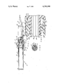
BRIEF DESCRIPTION OF THE DRAWINGS
FIG. 1 is a longitudinal elevation of a fountain pen, with parts broken away and shown in section;
FIG. 2 is a section on line 2--2 of FIG. 1;
FIG. 3 is an enlarged partial sectional view of the sealing of the cartridge to the pen.
DESCRIPTION OF THE PREFERRED EMBODIMENT
Referring now to the drawings, the fountain pen illustrated in FIG. 1 has the usual nib 10 which extends from a casing 12 and which is assembled on a feed bar 15, all of which is held in the casing by a securing nut 16. The end of the casing 12 remote from the nib has an interior threaded section 18. A partition 20 in the casing 12 has an outer threaded portion which engages casing threads 18 and a front end 22 which abuts the feed bar 15. The opposite end of the partition has firstly an elongated boss 24 with a bore 26 having one or more capillary channels 28 located therein and secondly an inner wall of the threaded portion which is coaxial with the boss 24.
A rear casing part 12' acts as a continuation of the main casing 12 and has a reduced end 13 which defines a shoulder 14 fitting snugly into and abutting the rear end of the casing 12. Screw threads 17 on the exterior of the casing part 12' receive the threaded portion of an end cap (not shown) while the interior bore receives the cartridge 30. The interior bore of the casing which receives the cartridge effectively has two diameters, namely a larger diameter at the part 12' and a smaller diameter by the inner wall of the partition member 20. In effect, the bore may be defined as a stepped bore to receive the cartridge 30.
A cartridge or ink reservoir 30 comprises essentially a hollow cylindrical body which may be formed of a suitable semi-rigid material such as plastic material, for example, polyethylene. The cartridge 30 has an outer cylindrical part 31 with a rear end wall 32, an intermediate tapered part 33 and a tapered nose part 34. The latter has a front end 35 from the inner portion of which there extends a double lip seal 36 which defeines a pair of lips 38 and 40. Also shown within the cartridge, is a ball 42 which initially seals the cartridge by extending across the double lip bore, it being opened by displacement when the lower end of the cartridge is inserted over the boss 24. The double lip formation 36 defines a forward lip 38 and a rearward lip 40. The rearward lip 40 is acted upon by the pressure of the ink within the cartridge 30 so that if the pressure within the cartridge increases, the lip 40 will be forced against the bore 24 with a greater force, thus preventing ink within the cartridge 30 from being forced out of it. Similarly should for some reason there be an excessive pressure on the outer portion exposed to the atmosphere at the location of the lip 38 a similar action will occur, thus ensuring that at all times regardless of the ambient pressures in existence, the cartridge will tightly seal about the boss 24. To further ensure sealing the tip 35a of the nose front end engages the partition 20.
The cartridge is shown as fully seated in the drawing and in this position the forward nose part engages the inner wall of the partition member at 48 to provide a seal and force the seals 36 inwardly. Additionally, the intermediate portion 33 engages the outer end of the casing as at 50. As will be apparent, points 48 and 50 are spaced apart and support the cartridge in its seated position. The support stabilizes the cartridge and prevents upset of the lip seal. The tapered sections also permit ease of insertion of the cartridge into the casing.
The cartridge is seated in the fountain pen in a manner to insure that no leakage occurs in airplanes (with reduced atmospheric pressure) as well as at sea level, by the simple expedient of having the portion designated at 48 serving as a seal and a pressure point for lip seals 38 and 40 along with a seal as at 35a, thus providing four sealing points.

Claims (3)

We claim:
1. In a fountain pen having a writing point, a feed bar and a casing for supporting the point and feed bar, a partition in the casing adjacent the feed bar having a cylindrical boss extending away from the feed bar with a bore therethrough, said bore having capillary slots in the wall thereof, a cartridge having a closed end and an open end and an exterior tapered nose, the open end having a sealing means located on the inner wall and spaced longitudinally inward of the open end, inner wall casing means engaging the tapered nose, said sealing means defining a protrusion with diverging lips, the inner diameter of the sealing means being smaller than the outer diameter of the boss, the engagement of said tapered nose with the inner wall forcing the sealing means inwardly whereby a tight joint is achieved by the sealing means engaging said cylindrical boss, a second seal being provided between the nose engagement point and the inner wall casing means, said open end engaging said partition to provide an additional seal.
2. In a fountain pen as in claim 1 wherein the nose of the cartridge is provided with a stepped tapered nose portion and the casing has a stepped inner wall to receive the cartridge.
3. In a fountain pen as in claim 1 or claim 2 wherein the partition comprises a re-entrant bore that defines a cylindrical inner wall within the casing extending about the cylindrical boss.
US06/277,862 1980-04-22 1981-06-26 Fountain pen cartridge Expired - Lifetime US4386866A (en)

Priority Applications (1)

Application Number Priority Date Filing Date Title
US06/277,862 US4386866A (en) 1980-04-22 1981-06-26 Fountain pen cartridge

Applications Claiming Priority (2)

Application Number Priority Date Filing Date Title
US14270180A 1980-04-22 1980-04-22
US06/277,862 US4386866A (en) 1980-04-22 1981-06-26 Fountain pen cartridge

Related Parent Applications (1)

Application Number Title Priority Date Filing Date
US14270180A Continuation-In-Part 1980-04-22 1980-04-22

Publications (1)

Publication Number Publication Date
US4386866A true US4386866A (en) 1983-06-07

Family

ID=26840343

Family Applications (1)

Application Number Title Priority Date Filing Date
US06/277,862 Expired - Lifetime US4386866A (en) 1980-04-22 1981-06-26 Fountain pen cartridge

Country Status (1)

Country Link
US (1) US4386866A (en)

Cited By (2)

* Cited by examiner, † Cited by third party
Publication number Priority date Publication date Assignee Title
US6921223B2 (en) 2003-09-15 2005-07-26 Sanford, L.P. Combo pen
US20150298487A1 (en) * 2012-11-16 2015-10-22 Louis Vuitton Malletier Fountain pen

Citations (8)

* Cited by examiner, † Cited by third party
Publication number Priority date Publication date Assignee Title
GB878117A (en) * 1959-08-27 1961-09-27 Fagard A J & Cie Improvements in or relating to fountain pens
DE1151751B (en) * 1958-04-26 1963-07-18 Hennefer Schreibwaren Fabrik R Fountain pen with exchangeable ink cartridge housed in a receptacle
FR86673E (en) * 1964-10-27 1966-03-25 Christian Ets Device for adapting reservoir bags to sections of stylographs and the like
FR1507251A (en) * 1966-11-15 1967-12-29 Foyer & Cie Le Pen ink cartridge
FR1571383A (en) * 1967-03-25 1969-06-20
US3521969A (en) * 1968-02-03 1970-07-28 Otto Mutschler Front end assembly for a fountain pen
US3532436A (en) * 1966-12-10 1970-10-06 Montblanc Simplo Gmbh Feed bar for fountain pens
DE2003229A1 (en) * 1970-01-24 1971-07-29 Montblanc Simplo Gmbh Cartridge fountain pen

Patent Citations (8)

* Cited by examiner, † Cited by third party
Publication number Priority date Publication date Assignee Title
DE1151751B (en) * 1958-04-26 1963-07-18 Hennefer Schreibwaren Fabrik R Fountain pen with exchangeable ink cartridge housed in a receptacle
GB878117A (en) * 1959-08-27 1961-09-27 Fagard A J & Cie Improvements in or relating to fountain pens
FR86673E (en) * 1964-10-27 1966-03-25 Christian Ets Device for adapting reservoir bags to sections of stylographs and the like
FR1507251A (en) * 1966-11-15 1967-12-29 Foyer & Cie Le Pen ink cartridge
US3532436A (en) * 1966-12-10 1970-10-06 Montblanc Simplo Gmbh Feed bar for fountain pens
FR1571383A (en) * 1967-03-25 1969-06-20
US3521969A (en) * 1968-02-03 1970-07-28 Otto Mutschler Front end assembly for a fountain pen
DE2003229A1 (en) * 1970-01-24 1971-07-29 Montblanc Simplo Gmbh Cartridge fountain pen

Cited By (3)

* Cited by examiner, † Cited by third party
Publication number Priority date Publication date Assignee Title
US6921223B2 (en) 2003-09-15 2005-07-26 Sanford, L.P. Combo pen
US20150298487A1 (en) * 2012-11-16 2015-10-22 Louis Vuitton Malletier Fountain pen
US9902191B2 (en) * 2012-11-16 2018-02-27 Louis Vuitton Malletier Fountain pen

Similar Documents

Publication Publication Date Title
US4496258A (en) Writing pen with space behind nib
US3951555A (en) Modular writing pen
JP2534821B2 (en) Writing instrument
US5711626A (en) Ball-point pen with back flow stop
US4239408A (en) Fountain pen with improved ink flow control
US5655847A (en) Ball-point pen
US4386866A (en) Fountain pen cartridge
GB2074104A (en) Fountain pen
US4209263A (en) Structure for reduced ink evaporation
US5678942A (en) Ball-point pen
US4311403A (en) Ball-point pen device
US4930921A (en) Tubular writting pen with superposed pressure equalization chambers
US5762435A (en) Cap for writing instrument
US3521969A (en) Front end assembly for a fountain pen
US3756733A (en) Tubular writing pen
US5738459A (en) "Pressurized refill with multiple seal valve core plug and a method for pressurizing a refill"
EP0626276A1 (en) A ball-point pen
GB970407A (en) Writing instrument
EP0472660A1 (en) A pen.
US3424538A (en) Pen
US3901608A (en) Writing instrument
US2846977A (en) Ball point pen
GB1126699A (en) Writing instruments
US2736292A (en) Ink feed device for fountain pens
US3458267A (en) Writing instrument

Legal Events

Date Code Title Description
STCF Information on status: patent grant

Free format text: PATENTED CASE

MAFP Maintenance fee payment

Free format text: PAYMENT OF MAINTENANCE FEE, 4TH YEAR, PL 96-517 (ORIGINAL EVENT CODE: M170); ENTITY STATUS OF PATENT OWNER: SMALL ENTITY

Year of fee payment: 4

FEPP Fee payment procedure

Free format text: PAYMENT IS IN EXCESS OF AMOUNT REQUIRED. REFUND SCHEDULED (ORIGINAL EVENT CODE: F169); ENTITY STATUS OF PATENT OWNER: SMALL ENTITY

MAFP Maintenance fee payment

Free format text: PAYMENT OF MAINTENANCE FEE, 8TH YEAR, PL 96-517 (ORIGINAL EVENT CODE: M171); ENTITY STATUS OF PATENT OWNER: SMALL ENTITY

Year of fee payment: 8

MAFP Maintenance fee payment

Free format text: PAYMENT OF MAINTENANCE FEE, 12TH YR, SMALL ENTITY (ORIGINAL EVENT CODE: M285); ENTITY STATUS OF PATENT OWNER: SMALL ENTITY

Year of fee payment: 12