US4397404A - Plastic containers and covers - Google Patents
Plastic containers and covers Download PDFInfo
- Publication number
- US4397404A US4397404A US06/305,950 US30595081A US4397404A US 4397404 A US4397404 A US 4397404A US 30595081 A US30595081 A US 30595081A US 4397404 A US4397404 A US 4397404A
- Authority
- US
- United States
- Prior art keywords
- cover
- container
- containers
- tubular wall
- annular
- Prior art date
- Legal status (The legal status is an assumption and is not a legal conclusion. Google has not performed a legal analysis and makes no representation as to the accuracy of the status listed.)
- Expired - Lifetime
Links
Images


Classifications
-
- B—PERFORMING OPERATIONS; TRANSPORTING
- B65—CONVEYING; PACKING; STORING; HANDLING THIN OR FILAMENTARY MATERIAL
- B65D—CONTAINERS FOR STORAGE OR TRANSPORT OF ARTICLES OR MATERIALS, e.g. BAGS, BARRELS, BOTTLES, BOXES, CANS, CARTONS, CRATES, DRUMS, JARS, TANKS, HOPPERS, FORWARDING CONTAINERS; ACCESSORIES, CLOSURES, OR FITTINGS THEREFOR; PACKAGING ELEMENTS; PACKAGES
- B65D21/00—Nestable, stackable or joinable containers; Containers of variable capacity
- B65D21/02—Containers specially shaped, or provided with fittings or attachments, to facilitate nesting, stacking, or joining together
- B65D21/0209—Containers specially shaped, or provided with fittings or attachments, to facilitate nesting, stacking, or joining together stackable or joined together one-upon-the-other in the upright or upside-down position
- B65D21/0217—Containers with a closure presenting stacking elements
- B65D21/022—Containers with a closure presenting stacking elements the bottom presenting projecting peripheral elements receiving or surrounding the closure or peripheral elements projecting therefrom
-
- B—PERFORMING OPERATIONS; TRANSPORTING
- B65—CONVEYING; PACKING; STORING; HANDLING THIN OR FILAMENTARY MATERIAL
- B65D—CONTAINERS FOR STORAGE OR TRANSPORT OF ARTICLES OR MATERIALS, e.g. BAGS, BARRELS, BOTTLES, BOXES, CANS, CARTONS, CRATES, DRUMS, JARS, TANKS, HOPPERS, FORWARDING CONTAINERS; ACCESSORIES, CLOSURES, OR FITTINGS THEREFOR; PACKAGING ELEMENTS; PACKAGES
- B65D43/00—Lids or covers for rigid or semi-rigid containers
- B65D43/02—Removable lids or covers
- B65D43/0202—Removable lids or covers without integral tamper element
- B65D43/0204—Removable lids or covers without integral tamper element secured by snapping over beads or projections
- B65D43/0206—Removable lids or covers without integral tamper element secured by snapping over beads or projections inside a peripheral U-shaped channel in the mouth of the container
-
- B—PERFORMING OPERATIONS; TRANSPORTING
- B65—CONVEYING; PACKING; STORING; HANDLING THIN OR FILAMENTARY MATERIAL
- B65D—CONTAINERS FOR STORAGE OR TRANSPORT OF ARTICLES OR MATERIALS, e.g. BAGS, BARRELS, BOTTLES, BOXES, CANS, CARTONS, CRATES, DRUMS, JARS, TANKS, HOPPERS, FORWARDING CONTAINERS; ACCESSORIES, CLOSURES, OR FITTINGS THEREFOR; PACKAGING ELEMENTS; PACKAGES
- B65D2543/00—Lids or covers essentially for box-like containers
- B65D2543/00009—Details of lids or covers for rigid or semi-rigid containers
- B65D2543/00018—Overall construction of the lid
- B65D2543/00064—Shape of the outer periphery
- B65D2543/00074—Shape of the outer periphery curved
- B65D2543/00092—Shape of the outer periphery curved circular
-
- B—PERFORMING OPERATIONS; TRANSPORTING
- B65—CONVEYING; PACKING; STORING; HANDLING THIN OR FILAMENTARY MATERIAL
- B65D—CONTAINERS FOR STORAGE OR TRANSPORT OF ARTICLES OR MATERIALS, e.g. BAGS, BARRELS, BOTTLES, BOXES, CANS, CARTONS, CRATES, DRUMS, JARS, TANKS, HOPPERS, FORWARDING CONTAINERS; ACCESSORIES, CLOSURES, OR FITTINGS THEREFOR; PACKAGING ELEMENTS; PACKAGES
- B65D2543/00—Lids or covers essentially for box-like containers
- B65D2543/00009—Details of lids or covers for rigid or semi-rigid containers
- B65D2543/00018—Overall construction of the lid
- B65D2543/00259—Materials used
- B65D2543/00296—Plastic
-
- B—PERFORMING OPERATIONS; TRANSPORTING
- B65—CONVEYING; PACKING; STORING; HANDLING THIN OR FILAMENTARY MATERIAL
- B65D—CONTAINERS FOR STORAGE OR TRANSPORT OF ARTICLES OR MATERIALS, e.g. BAGS, BARRELS, BOTTLES, BOXES, CANS, CARTONS, CRATES, DRUMS, JARS, TANKS, HOPPERS, FORWARDING CONTAINERS; ACCESSORIES, CLOSURES, OR FITTINGS THEREFOR; PACKAGING ELEMENTS; PACKAGES
- B65D2543/00—Lids or covers essentially for box-like containers
- B65D2543/00009—Details of lids or covers for rigid or semi-rigid containers
- B65D2543/00444—Contact between the container and the lid
- B65D2543/00453—Contact between the container and the lid in a peripheral U-shaped channel of the container
- B65D2543/00472—Skirt
-
- B—PERFORMING OPERATIONS; TRANSPORTING
- B65—CONVEYING; PACKING; STORING; HANDLING THIN OR FILAMENTARY MATERIAL
- B65D—CONTAINERS FOR STORAGE OR TRANSPORT OF ARTICLES OR MATERIALS, e.g. BAGS, BARRELS, BOTTLES, BOXES, CANS, CARTONS, CRATES, DRUMS, JARS, TANKS, HOPPERS, FORWARDING CONTAINERS; ACCESSORIES, CLOSURES, OR FITTINGS THEREFOR; PACKAGING ELEMENTS; PACKAGES
- B65D2543/00—Lids or covers essentially for box-like containers
- B65D2543/00009—Details of lids or covers for rigid or semi-rigid containers
- B65D2543/00444—Contact between the container and the lid
- B65D2543/00481—Contact between the container and the lid on the inside or the outside of the container
- B65D2543/0049—Contact between the container and the lid on the inside or the outside of the container on the inside, or a part turned to the inside of the mouth of the container
- B65D2543/00509—Cup
-
- B—PERFORMING OPERATIONS; TRANSPORTING
- B65—CONVEYING; PACKING; STORING; HANDLING THIN OR FILAMENTARY MATERIAL
- B65D—CONTAINERS FOR STORAGE OR TRANSPORT OF ARTICLES OR MATERIALS, e.g. BAGS, BARRELS, BOTTLES, BOXES, CANS, CARTONS, CRATES, DRUMS, JARS, TANKS, HOPPERS, FORWARDING CONTAINERS; ACCESSORIES, CLOSURES, OR FITTINGS THEREFOR; PACKAGING ELEMENTS; PACKAGES
- B65D2543/00—Lids or covers essentially for box-like containers
- B65D2543/00009—Details of lids or covers for rigid or semi-rigid containers
- B65D2543/00444—Contact between the container and the lid
- B65D2543/00481—Contact between the container and the lid on the inside or the outside of the container
- B65D2543/00537—Contact between the container and the lid on the inside or the outside of the container on the outside, or a part turned to the outside of the mouth of the container
- B65D2543/00546—NO contact
-
- B—PERFORMING OPERATIONS; TRANSPORTING
- B65—CONVEYING; PACKING; STORING; HANDLING THIN OR FILAMENTARY MATERIAL
- B65D—CONTAINERS FOR STORAGE OR TRANSPORT OF ARTICLES OR MATERIALS, e.g. BAGS, BARRELS, BOTTLES, BOXES, CANS, CARTONS, CRATES, DRUMS, JARS, TANKS, HOPPERS, FORWARDING CONTAINERS; ACCESSORIES, CLOSURES, OR FITTINGS THEREFOR; PACKAGING ELEMENTS; PACKAGES
- B65D2543/00—Lids or covers essentially for box-like containers
- B65D2543/00009—Details of lids or covers for rigid or semi-rigid containers
- B65D2543/00444—Contact between the container and the lid
- B65D2543/00592—Snapping means
- B65D2543/00601—Snapping means on the container
- B65D2543/00611—Profiles
- B65D2543/00629—Massive bead
-
- B—PERFORMING OPERATIONS; TRANSPORTING
- B65—CONVEYING; PACKING; STORING; HANDLING THIN OR FILAMENTARY MATERIAL
- B65D—CONTAINERS FOR STORAGE OR TRANSPORT OF ARTICLES OR MATERIALS, e.g. BAGS, BARRELS, BOTTLES, BOXES, CANS, CARTONS, CRATES, DRUMS, JARS, TANKS, HOPPERS, FORWARDING CONTAINERS; ACCESSORIES, CLOSURES, OR FITTINGS THEREFOR; PACKAGING ELEMENTS; PACKAGES
- B65D2543/00—Lids or covers essentially for box-like containers
- B65D2543/00009—Details of lids or covers for rigid or semi-rigid containers
- B65D2543/00444—Contact between the container and the lid
- B65D2543/00592—Snapping means
- B65D2543/00601—Snapping means on the container
- B65D2543/00675—Periphery concerned
- B65D2543/00685—Totality
-
- B—PERFORMING OPERATIONS; TRANSPORTING
- B65—CONVEYING; PACKING; STORING; HANDLING THIN OR FILAMENTARY MATERIAL
- B65D—CONTAINERS FOR STORAGE OR TRANSPORT OF ARTICLES OR MATERIALS, e.g. BAGS, BARRELS, BOTTLES, BOXES, CANS, CARTONS, CRATES, DRUMS, JARS, TANKS, HOPPERS, FORWARDING CONTAINERS; ACCESSORIES, CLOSURES, OR FITTINGS THEREFOR; PACKAGING ELEMENTS; PACKAGES
- B65D2543/00—Lids or covers essentially for box-like containers
- B65D2543/00009—Details of lids or covers for rigid or semi-rigid containers
- B65D2543/00444—Contact between the container and the lid
- B65D2543/00592—Snapping means
- B65D2543/00712—Snapping means on the lid
- B65D2543/00722—Profiles
- B65D2543/0074—Massive bead
-
- B—PERFORMING OPERATIONS; TRANSPORTING
- B65—CONVEYING; PACKING; STORING; HANDLING THIN OR FILAMENTARY MATERIAL
- B65D—CONTAINERS FOR STORAGE OR TRANSPORT OF ARTICLES OR MATERIALS, e.g. BAGS, BARRELS, BOTTLES, BOXES, CANS, CARTONS, CRATES, DRUMS, JARS, TANKS, HOPPERS, FORWARDING CONTAINERS; ACCESSORIES, CLOSURES, OR FITTINGS THEREFOR; PACKAGING ELEMENTS; PACKAGES
- B65D2543/00—Lids or covers essentially for box-like containers
- B65D2543/00009—Details of lids or covers for rigid or semi-rigid containers
- B65D2543/00444—Contact between the container and the lid
- B65D2543/00592—Snapping means
- B65D2543/00712—Snapping means on the lid
- B65D2543/00787—Periphery concerned
- B65D2543/00796—Totality
-
- B—PERFORMING OPERATIONS; TRANSPORTING
- B65—CONVEYING; PACKING; STORING; HANDLING THIN OR FILAMENTARY MATERIAL
- B65D—CONTAINERS FOR STORAGE OR TRANSPORT OF ARTICLES OR MATERIALS, e.g. BAGS, BARRELS, BOTTLES, BOXES, CANS, CARTONS, CRATES, DRUMS, JARS, TANKS, HOPPERS, FORWARDING CONTAINERS; ACCESSORIES, CLOSURES, OR FITTINGS THEREFOR; PACKAGING ELEMENTS; PACKAGES
- B65D2543/00—Lids or covers essentially for box-like containers
- B65D2543/00009—Details of lids or covers for rigid or semi-rigid containers
- B65D2543/00824—Means for facilitating removing of the closure
- B65D2543/00888—Means for facilitating removing of the closure by applying lever forces
- B65D2543/00898—Means for facilitating removing of the closure by applying lever forces by means of a coin or other tool in recesses or similar on container or lid
Definitions
- This invention relates to a capped plastic container with straight sides and more particularly to a plastic container with a stiff cover and three locking connections for the cover inside the rim of the container.
- Containers with covers that make a seal with the top of the container so as to result in a capped container with straight sides are well known. Capped containers of this type are needed in some businesses, such as the paint industry, because they will roll in a straight line, as required by existing machinery used for applying labels to containers. Such containers are usually made of metal, especially in the paint industry.
- Plastic containers with mating covers are exemplified in U.S. Pat. No. 4,210,258. Still other designs of plastic containers and covers are described in the references cited in the foregoing U.S. patent and also in British Pat. No. 1,582,416 filed on Apr. 12, 1978.
- the primary object of this invention is to provide a new plastic container and cover that is designed so as to eliminate or substantially reduce the problems noted above.
- Another object is to provide a plastic container and a mating plastic cover that simultaneously (a) provides a flush fit between the cover and the upper rim and sidewall of the container, thereby resulting in a capped container with straight sides, (b) provides for all locking connections to be on the inner side of the top rim and sidewall of the container, and (c) provides for easy removal of the cover using conventional methods.
- a further object is to provide a capped plastic container of the type described that can withstand the impact forces produced when it is dropped onto its side from a significant height, whereby the cover remains sealed to the container without any spilling of the contents of the container.
- a container/cover arrangement that in its preferred embodiment essentially comprises a plastic container with a cylindrical sidewall, a circular bottom wall, and a substantially stiff plastic cover with an outer lip.
- the container has an annular flange on the inner side of its sidewall adjacent its top rim.
- An annular upwardly-facing slot is formed by the flange and the upper end of the sidewall.
- the slot is designed to receive an annular wall extending downward from the outer lip of the cover. The annular wall, when positioned in the slot, is frictionally gripped by two of the surfaces defining the slot.
- a third locking connection is provided by the innermost portion of the flange when it is positioned between the annular wall and a second concentric inner wall also extending downward from the outer lip of the cover, whereby the innermost upwardly-extending portion of the flange is also frictionally engaged by at least one of the surfaces between the two annular walls.
- All three locking connections are on the inner side of the container sidewall.
- the container sidewall extends below the bottom wall so as to form a bottom ridge that, when coupled with upwardly-extending projections on the top of the cover, prevents stacked containers from sliding laterally.
- the container also has two ears on diametrically opposed portions of its sidewall to retain a bail.
- FIG. 1 is a side elevational view of a preferred form of a container and cover constructed in accordance with this invention, the drawing also showing a fragmentary sectional view of the bottom wall and sidewall of the container;
- FIG. 2 is an enlarged fragmentary sectional view in elevation of the top portion of the container and cover of FIG. 1 with the cover a short distance above the container in position to be pushed straight downward and sealed to the container;
- FIG. 3 is an enlarged fragmentary side sectional view of the same container and cover after the cover has been pushed down and sealed to the container by a capping device;
- FIG. 4 is an enlarged fragmentary sectional view in elevation of the same container and cover with the cover sealed to the container, and with the bottom of an identical second container in position to be stacked on top of the first container;
- FIG. 5 is a fragmentary side elevational view of the top of the same container and cover with the cover sealed to the container and showing a removal slot in the cover;
- FIG. 6 is a fragmentary bottom view of the outer lip of the same cover showing the same removal slot of FIG. 5;
- FIG. 7 is an enlarged fragmentary sectional view in elevation of the same container and cover showing the cover being pried off the container by the end of an opening tool inserted into the same removal slot in the cover;
- FIG. 8 is a fragmentary side elevational view of the top of a modified container with a removal slot in its top outer edge;
- FIG. 9 is an enlarged fragmentary sectional view in elevation of the top portion of a modified container and cover with the cover sealed to the container;
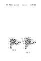
- FIG. 10 is an enlarged fragmentary sectional view in elevation of the top of a modified container and cover with the cover sealed to the container;
- FIG. 11 is an enlarged fragmentary sectional view of the modified container and cover of FIG. 10 with the cover being pried off by the end of an opening tool inserted into a removal slot in the cover.
- the illustrated apparatus comprises a container 2, a cover 4, two ears 6 integrally molded with the container, and a bail 8.
- container 2 comprises a cylindrical sidewall 10, a circular bottom wall 12, and an annular flange 14 projecting inward from the upper end of sidewall 10.
- the upper end of sidewall 10 terminates in a top rim 16.
- Bottom wall 12 has a circular depression 18 curving upward at its center, and sidewall 10 extends downward below bottom wall 12 to form a bottom ridge 20.
- Flange 14 comprises two parts--an outer bottom portion 15 attached to sidewall 10 and extending radially inward where it is attached to a second inner portion 17 that extends upward in an axial direction.
- a slot 22 is formed by the inside surface of sidewall 10, the upper surface of outer portion 15, and the outside surface of inner portion 17.
- Slot 22 has a groove 24 in its outer bottom corner and a groove 26 in its inner bottom corner. Grooves 24 and 26 have the same radius of curvature.
- the inside surface of flange 14 has a third groove 28 with a radius of curvature greater than the radius of grooves 24 and 26.
- cover 4 has an annular outer lip 32, terminating in an outer edge 33, an outside wall 30 extending downward from outer lip 32, and an inside wall 34 that is concentric with outside wall 30 and joins outer lip 32 with an annular portion 35 that is connected in turn to an inner portion 36 of cover 4.
- a depression 37 is formed by wall 34 and portions 34 and 36.
- Outer lip 32 has two ribs or ridges 38 and 40 projecting upward; outer ridge 38 is directly above outside wall 30 and inner ridge 40 is directly above inside wall 34.
- Outside wall 30 has two beads 42 and 44 projecting from its bottom end. Outer bead 42 projects outward and makes a snug fit in groove 24, and inner bead 44 projects inward and makes a snug fit in groove 26.
- a third bead 46 projects outward from inside wall 34 and makes a snug fit in groove 28.
- cover 4 has a removal slot 48 formed in its outer edge 33. Slot 48 is perpendicular to the center axis of container 2.
- ears 6 are located at diametrically opposite positions and are provided with openings (not shown) to receive the opposite ends of bail 8.
- the ends of metal bail 8 are bent inwardly so as to form blocks which fit in the holes in ears 6 and pivotally secure the bail to the ears, whereby the bail can support the weight of the container 2 and its contents.
- cover 4 is shown in FIG. 2 before it is locked into place in container 2 and in FIG. 3 after it has been locked into place by a similar metal plate 56 which forms part of an automatic capping device (not shown). Normally, cover 4 would be pushed downward and locked into place on an assembly line by metal plate 56 of the automatic capping device. Ridges 38 and 40 are located directly above walls 30 and 34, respectively, so as to transmit the downward force of capping device member 56 to the walls 30 and 34, thereby to facilitate locking the cover to the containers by the snap-fit connections formed by beads 42, 44, and 46 and grooves 24, 26, and 28, respectively. Outer ridge 38 also serves to prevent stacked containers 2 from moving or sliding on the cover 4. As seen in FIG. 4, the bottom ridge 20 of a container 2 stacked on top of a second container 2 is restrained from moving laterally due to the close proximity of concentric ridge 38 just inside the bottom ridge 20.
- removal slot 48 allows a tool 58, such as a screwdriver, to be used to pry cover 4 off container 2.
- a tool 58 such as a screwdriver
- One end of tool 58 is inserted into slot 48 perpendicular to the center axis of container 2.
- the opposite end of tool 58 is pushed downward to apply an upward leveraged force to the outer lip 32 of cover 4 and thereby disengage beads 42, 44, and 46 from grooves 24, 26, and 28, respectively.
- Cover 4 can have one or more removal slots 48 as reasonably desired.
- Cover 4 is manufactured so as to be substantially stiff.
- Container 2 also is stiff but has sufficient resiliency for its rim and flange to be bendable for attachment and removal of the cover as shown in FIGS. 3 and 7. Therefore, rim 16 and flange 14 grip cover 4 when cover 4 is locked into place, and the stiffness of cover 4 provides for a more positive locking action during automatic capping on an assembly line than experienced in prior art containers and covers utilizing a resilient cover with a rigid or stiff container.
- the invention has other advantages as well.
- the outer edge 33 of cover 4 lies flush with sidewall 10 when cover 4 is locked into place. This flush fit is similar to that achieved with other prior art containers and covers of different design and is important in that it meets the paint industry's requirement that containers and covers form straight sides to allow the capped containers to roll in a straight line, thereby allowing paper labels to be applied to the containers by currently existing labelling machinery in which capped containers lie and roll on their side during the labelling operation.
- this invention is an improvement over containers and covers of prior known design because the cover 4 is less likely to become dislodged from the container 2 by accidentally catching on other objects such as loading pallets or other containers. This advantage results from the location of flange 14 on the inner side of sidewall 10.
- FIG. 8 shows a modification to the container 2 and cover 4 of FIG. 1 in that removal slot 48A is manufactured into the top rim 16 of container 2 rather than the outer edge 33 of cover 4.
- FIG. 9 shows a container 2 and cover 4 similar to those in FIG. 1; however, the innermost locking connection has been modified by replacing bead 46 with a lip 46A; also groove 28 has been replaced by a straight inner surface 28A so that flange 14 lies flush against a straight outside surface of wall 34.
- Lip 46A forms the modified locking connection by wrapping around the inside bottom of the inner portion 17 of flange 14.
- FIGS. 10 and 11 show a container and cover similar to those in FIG. 1 with the two outside locking connections modified.
- the outermost locking connection has been modified by replacing bead 42 and groove 24 with a foot 42A and a matching groove 24A.
- the middle locking connection has been done away with completely by replacing bead 44 and groove 26 with straight surfaces 44A and 26A, respectively, on the inside surface of wall 30 and the inside surface of slot 22.
- the cover 4 has a removal slot 48 allowing it to be removed with an opening tool in the manner described for the container and cover in FIG. 1.
- a decided advantage of the invention is that it makes it possible to provide molded plastic containers with attached covers wherein (a) the containers have flat sides and the covers do not protrude beyond the outer periphery of the containers and (b) each cover is attached to a container by a plurality of sealing connections arranged so that if the container or cover is subjected to an impact which tends to loosen one or more of the sealing connections, at least one sealing connection will be unaffected or be improved by the impact.
- Another important advantage of the invention is that it allows substantially thinner wall sections to be used throughout the container and the cover than is permissible with prior designs. In this connection it is to be noted that in the embodiments shown in FIGS.
- various sections of the container and cover e.g., section 10, 15, 16, 17, 30, 34, 35 and 36, may have thicknesses which vary from one another by relatively small amounts. Having relatively small cross-sectional thicknesses throughout the locking connections between the container and cover is advantageous in that the cycle time of the usual molding operation depends upon the maximum wall thickness of the part being molded. In general, the greater the wall thickness of the molded part, the longer the cycle time.
- sections 16, 30, 17 and 34 are so dimensioned that when the cover and container are locked together, those sections together form a substantially square section (see FIG. 3).
- This square cross-sectional configuration provides substantial rigidity which (a) allows a number of filled containers to be stacked one upon the other without any damaging deformation and (b) helps to preserve the integrity of the locking connection between the container and cover under various conditions.
- Containers embodying the present invention may be made with conventional molding equipment using molds having collapsible cores according to techniques well known to persons skilled in the art.
- grooves 24 and 26 may have different radii of curvature and different depths.
- groove 24 preferably has a greater depth than groove 26.
- ribs 38 and 40 serve to strengthen the cover as well as to facilitate stacking, and these ribs may have a different cross-sectional shape.
- one of the ribs 38 and 40 may be omitted or one or more ribs may be added to the cover.
Abstract
Description
Claims (6)
Priority Applications (1)
| Application Number | Priority Date | Filing Date | Title |
|---|---|---|---|
| US06/305,950 US4397404A (en) | 1981-09-28 | 1981-09-28 | Plastic containers and covers |
Applications Claiming Priority (1)
| Application Number | Priority Date | Filing Date | Title |
|---|---|---|---|
| US06/305,950 US4397404A (en) | 1981-09-28 | 1981-09-28 | Plastic containers and covers |
Publications (1)
| Publication Number | Publication Date |
|---|---|
| US4397404A true US4397404A (en) | 1983-08-09 |
Family
ID=23183063
Family Applications (1)
| Application Number | Title | Priority Date | Filing Date |
|---|---|---|---|
| US06/305,950 Expired - Lifetime US4397404A (en) | 1981-09-28 | 1981-09-28 | Plastic containers and covers |
Country Status (1)
| Country | Link |
|---|---|
| US (1) | US4397404A (en) |
Cited By (61)
| Publication number | Priority date | Publication date | Assignee | Title |
|---|---|---|---|---|
| US4491238A (en) * | 1983-12-12 | 1985-01-01 | Tobolt Michael J | Receptacle having a plug closure |
| US4512494A (en) * | 1983-02-28 | 1985-04-23 | Holdt J W Von | Plastic container having tongue and groove retention |
| US4524882A (en) * | 1983-06-20 | 1985-06-25 | Buc John L | Molded container and closure |
| US4606474A (en) * | 1984-12-19 | 1986-08-19 | Mardon Illingworth Limited | Container with plug-fitting lid |
| US4770318A (en) * | 1982-09-30 | 1988-09-13 | Dart Container Corporation | Interlocking lid and associated container |
| US4819824A (en) * | 1987-02-25 | 1989-04-11 | Barker, Brettell & Duncan | Lidded containers |
| US4823955A (en) * | 1987-08-27 | 1989-04-25 | Rehrig-Pacific Company, Inc. | Nesting and stacking storage container |
| US5097977A (en) * | 1991-02-27 | 1992-03-24 | Roy Straub | Closure assembly for container |
| US5125530A (en) * | 1991-02-27 | 1992-06-30 | Packaging Accessories Corporation | Closure assembly for container |
| WO1993023303A1 (en) * | 1992-05-14 | 1993-11-25 | Edwards Richard T | Latch for a container |
| US5437386A (en) * | 1993-08-11 | 1995-08-01 | Von Holdt; John W. | Container with tamper-evident lid removal means |
| US5476187A (en) * | 1992-11-12 | 1995-12-19 | Marisco; Frank J. | Retainer means for container liner |
| US6109515A (en) * | 1998-06-03 | 2000-08-29 | Duboff; Gary | Sealable container assembly |
| WO2001036285A1 (en) * | 1999-11-15 | 2001-05-25 | United States Can Company | Container and closure therefor |
| US6245277B1 (en) | 1999-03-30 | 2001-06-12 | John Clementi | Injection mold assembly for molding plastic containers |
| US6250494B1 (en) * | 1999-03-30 | 2001-06-26 | John Clementi | Plastic containers with interlocking lids |
| US6478183B1 (en) * | 2001-04-27 | 2002-11-12 | Sonoco Development, Inc. | Lightweight overcap having intermittent nesting and stacking elements |
| US6588618B1 (en) | 2001-04-26 | 2003-07-08 | Letica Corporation | Molded plastic container, snap ring and lid combination |
| US20030168465A1 (en) * | 2002-03-07 | 2003-09-11 | Breimon Mark S. | Plastic paint can |
| US20040000557A1 (en) * | 2002-05-23 | 2004-01-01 | William Shepler | Reusable storage container with latching mechanism |
| US20040074902A1 (en) * | 2002-10-22 | 2004-04-22 | Hayes Thomas J. | Containers and container assemblies with releasable locking feature |
| US20040195138A1 (en) * | 2003-04-01 | 2004-10-07 | Van Holdt John W. | Plastic bucket and lid stacking construction |
| US20050189350A1 (en) * | 2002-10-22 | 2005-09-01 | Pactiv Corporation | Container assemblies with releasable locking feature |
| US20060000076A1 (en) * | 2002-10-22 | 2006-01-05 | Hayes Thomas J | Method of using a container assembly |
| US20060043095A1 (en) * | 2004-08-26 | 2006-03-02 | Maholm Gary M | Paint container |
| US20060071457A1 (en) * | 2004-10-04 | 2006-04-06 | Schneider David W | Airbag cover attachment and opening assembly |
| US20060138141A1 (en) * | 2004-12-17 | 2006-06-29 | Stolzman Michael D | Reduced thickness cover |
| US20060159807A1 (en) * | 2002-10-22 | 2006-07-20 | Hayes Thomas J | Container assemblies with releasable locking feature |
| US20060243735A1 (en) * | 2005-04-29 | 2006-11-02 | Kline Terry L | Plastic paint can |
| US20060261067A1 (en) * | 2005-05-20 | 2006-11-23 | Letica Corporation | Molded plastic container combination including a snap-on snap ring |
| US20070023428A1 (en) * | 2005-07-26 | 2007-02-01 | Pactiv Corporation | Container assemblies with releasable locking feature |
| US20070029318A1 (en) * | 2005-08-02 | 2007-02-08 | Ooi Kee S | Continuous seal container assembly |
| WO2007065225A1 (en) * | 2005-12-09 | 2007-06-14 | Andrew Kirsh | A container with a fluid seal |
| US20070172554A1 (en) * | 2005-09-30 | 2007-07-26 | Pactiv Corporation | Modular container assembly and merchandizing container display |
| US20080035658A1 (en) * | 2006-08-10 | 2008-02-14 | Capitol Vial Inc. | Container and Cap Assembly |
| US20090065514A1 (en) * | 2007-09-06 | 2009-03-12 | Terry Vovan | Invertible tray |
| US20090236354A1 (en) * | 2005-12-06 | 2009-09-24 | Brasilata S/A Embalagens | Can closure arrangement |
| US20100229689A1 (en) * | 2009-03-13 | 2010-09-16 | Jeffrey Minnette | Device for opening container closures |
| US20110036804A1 (en) * | 2009-08-13 | 2011-02-17 | Letica, Inc. | Plastic Pry Off Paint Can Assembly |
| US20110089187A1 (en) * | 2006-08-10 | 2011-04-21 | Capitol Vial Inc. | Shatterproof Container And Cap Assembly |
| US20130075413A1 (en) * | 2009-08-13 | 2013-03-28 | Letica Corporation | Plastic pry-off paint can assembly |
| US8827096B1 (en) * | 2011-09-09 | 2014-09-09 | Donald E. Macpherson | Combination paint can and non-splash lid which eliminates the sump area at the top of the paint can and provides a mating recess on the bottom of the paint can to facilitate stacking one paint can on top of another paint can |
| US8985383B2 (en) * | 2012-06-22 | 2015-03-24 | Kw Container | Plastic container and lid |
| US9371153B1 (en) * | 2015-03-04 | 2016-06-21 | Modern Twist, Inc. | Shaped elastomeric container with integrated leak resistant seal |
| US20180002076A1 (en) * | 2015-03-26 | 2018-01-04 | Toppan Printing Co., Ltd. | Lidded container |
| USD818319S1 (en) | 2016-08-17 | 2018-05-22 | Reynolds Consumer Products LLC | Plate |
| USD823645S1 (en) | 2016-06-06 | 2018-07-24 | Reynolds Consumer Products LLC | Plate |
| USD823644S1 (en) | 2016-06-06 | 2018-07-24 | Reynolds Consumer Products LLC | Plate |
| US10407217B1 (en) | 2018-11-16 | 2019-09-10 | Stasher, Inc. | Method of manufacturing a container with a leak resistant seal |
| US10625906B1 (en) | 2018-11-16 | 2020-04-21 | Stasher, Inc. | Inside out method of manufacturing a container with a leak resistant seal |
| EP3257775B1 (en) | 2016-06-15 | 2020-08-19 | Envases de Plasticos Vargas, S. L. | Container for food stuffs |
| WO2020176669A1 (en) * | 2019-02-26 | 2020-09-03 | Bway Corporation | Container and seal assembly |
| USD903483S1 (en) | 2018-11-16 | 2020-12-01 | Stasher, Inc. | Sealable container |
| US11124330B2 (en) | 2020-02-06 | 2021-09-21 | Stasher, Inc. | Shaped elastomeric container with integrated leak resistant seal and pressure shield |
| USD933324S1 (en) * | 2020-02-26 | 2021-10-12 | Bway Corporation | Container |
| USD942724S1 (en) * | 2020-02-26 | 2022-02-01 | Bway Corporation | Container |
| US20220031926A1 (en) * | 2020-07-28 | 2022-02-03 | Design Department, Inc. | Spherical Canister |
| US11533896B1 (en) * | 2021-08-23 | 2022-12-27 | Jesse Jonah White | Insect trap lid for buckets |
| US11873143B2 (en) | 2020-02-06 | 2024-01-16 | Stasher, Inc. | Shaped elastomeric container with integrated leak resistant seal and pressure shield |
| USD1011671S1 (en) | 1991-07-02 | 2024-01-16 | Bway Corporation | Container |
| USD1015669S1 (en) | 2020-02-26 | 2024-02-20 | Bway Corporation | Container ring |
Citations (4)
| Publication number | Priority date | Publication date | Assignee | Title |
|---|---|---|---|---|
| US3514011A (en) * | 1969-02-06 | 1970-05-26 | Plasti Kote Corp | Tamper-proof closure for spray cans |
| US4210258A (en) * | 1978-03-02 | 1980-07-01 | Holdt J W Von | Seal for plastic buckets and cans |
| US4308970A (en) * | 1978-11-27 | 1982-01-05 | Holdt J W Von | Plastic bucket defining annular inwardly projecting ridge |
| US4334631A (en) * | 1980-11-24 | 1982-06-15 | Ballester Jose F | Cover and container assembly |
-
1981
- 1981-09-28 US US06/305,950 patent/US4397404A/en not_active Expired - Lifetime
Patent Citations (4)
| Publication number | Priority date | Publication date | Assignee | Title |
|---|---|---|---|---|
| US3514011A (en) * | 1969-02-06 | 1970-05-26 | Plasti Kote Corp | Tamper-proof closure for spray cans |
| US4210258A (en) * | 1978-03-02 | 1980-07-01 | Holdt J W Von | Seal for plastic buckets and cans |
| US4308970A (en) * | 1978-11-27 | 1982-01-05 | Holdt J W Von | Plastic bucket defining annular inwardly projecting ridge |
| US4334631A (en) * | 1980-11-24 | 1982-06-15 | Ballester Jose F | Cover and container assembly |
Cited By (91)
| Publication number | Priority date | Publication date | Assignee | Title |
|---|---|---|---|---|
| US4770318A (en) * | 1982-09-30 | 1988-09-13 | Dart Container Corporation | Interlocking lid and associated container |
| US4512494A (en) * | 1983-02-28 | 1985-04-23 | Holdt J W Von | Plastic container having tongue and groove retention |
| US4524882A (en) * | 1983-06-20 | 1985-06-25 | Buc John L | Molded container and closure |
| US4491238A (en) * | 1983-12-12 | 1985-01-01 | Tobolt Michael J | Receptacle having a plug closure |
| US4606474A (en) * | 1984-12-19 | 1986-08-19 | Mardon Illingworth Limited | Container with plug-fitting lid |
| US4819824A (en) * | 1987-02-25 | 1989-04-11 | Barker, Brettell & Duncan | Lidded containers |
| US4823955A (en) * | 1987-08-27 | 1989-04-25 | Rehrig-Pacific Company, Inc. | Nesting and stacking storage container |
| US5097977A (en) * | 1991-02-27 | 1992-03-24 | Roy Straub | Closure assembly for container |
| US5125530A (en) * | 1991-02-27 | 1992-06-30 | Packaging Accessories Corporation | Closure assembly for container |
| USD1011671S1 (en) | 1991-07-02 | 2024-01-16 | Bway Corporation | Container |
| US5339973A (en) * | 1992-05-14 | 1994-08-23 | Genpak Corp. | Latch for a container |
| WO1993023303A1 (en) * | 1992-05-14 | 1993-11-25 | Edwards Richard T | Latch for a container |
| US5476187A (en) * | 1992-11-12 | 1995-12-19 | Marisco; Frank J. | Retainer means for container liner |
| US5437386A (en) * | 1993-08-11 | 1995-08-01 | Von Holdt; John W. | Container with tamper-evident lid removal means |
| US6109515A (en) * | 1998-06-03 | 2000-08-29 | Duboff; Gary | Sealable container assembly |
| US6250494B1 (en) * | 1999-03-30 | 2001-06-26 | John Clementi | Plastic containers with interlocking lids |
| US6245277B1 (en) | 1999-03-30 | 2001-06-12 | John Clementi | Injection mold assembly for molding plastic containers |
| US6491185B1 (en) | 1999-11-15 | 2002-12-10 | United States Can Company | Molded container including plug with multiple locking arms |
| WO2001036285A1 (en) * | 1999-11-15 | 2001-05-25 | United States Can Company | Container and closure therefor |
| US6588618B1 (en) | 2001-04-26 | 2003-07-08 | Letica Corporation | Molded plastic container, snap ring and lid combination |
| US6478183B1 (en) * | 2001-04-27 | 2002-11-12 | Sonoco Development, Inc. | Lightweight overcap having intermittent nesting and stacking elements |
| US6964348B2 (en) | 2002-03-07 | 2005-11-15 | Kw Plastics | Plastic paint can |
| US20030168465A1 (en) * | 2002-03-07 | 2003-09-11 | Breimon Mark S. | Plastic paint can |
| WO2003076288A1 (en) * | 2002-03-07 | 2003-09-18 | Kw Plastics | Plastic paint can |
| US20040000557A1 (en) * | 2002-05-23 | 2004-01-01 | William Shepler | Reusable storage container with latching mechanism |
| US6929145B2 (en) * | 2002-05-23 | 2005-08-16 | Rubbermaid Incorporated | Reusable storage container with latching mechanism |
| US6886704B2 (en) | 2002-10-22 | 2005-05-03 | Pactiv Corporation | Containers and container assemblies with releasable locking feature |
| US20050098554A1 (en) * | 2002-10-22 | 2005-05-12 | Hayes Thomas J. | Containers and container assemblies with releasable locking feature |
| US20050189350A1 (en) * | 2002-10-22 | 2005-09-01 | Pactiv Corporation | Container assemblies with releasable locking feature |
| US20050230389A1 (en) * | 2002-10-22 | 2005-10-20 | Hayes Thomas J | Container assemblies with releasable locking feature |
| US20060159807A1 (en) * | 2002-10-22 | 2006-07-20 | Hayes Thomas J | Container assemblies with releasable locking feature |
| US20060000076A1 (en) * | 2002-10-22 | 2006-01-05 | Hayes Thomas J | Method of using a container assembly |
| US20040074902A1 (en) * | 2002-10-22 | 2004-04-22 | Hayes Thomas J. | Containers and container assemblies with releasable locking feature |
| US20070007288A1 (en) * | 2002-10-22 | 2007-01-11 | Hayes Thomas J | Methods of using containers and container assemblies with interlocking features |
| US20040195138A1 (en) * | 2003-04-01 | 2004-10-07 | Van Holdt John W. | Plastic bucket and lid stacking construction |
| US20060043095A1 (en) * | 2004-08-26 | 2006-03-02 | Maholm Gary M | Paint container |
| US20060071457A1 (en) * | 2004-10-04 | 2006-04-06 | Schneider David W | Airbag cover attachment and opening assembly |
| US7261314B2 (en) * | 2004-10-04 | 2007-08-28 | Autoliv Asp, Inc. | Airbag cover attachment and opening assembly |
| US20060138141A1 (en) * | 2004-12-17 | 2006-06-29 | Stolzman Michael D | Reduced thickness cover |
| US20060243735A1 (en) * | 2005-04-29 | 2006-11-02 | Kline Terry L | Plastic paint can |
| US20060261067A1 (en) * | 2005-05-20 | 2006-11-23 | Letica Corporation | Molded plastic container combination including a snap-on snap ring |
| US8342354B2 (en) | 2005-05-20 | 2013-01-01 | Letica Corporation | Molded plastic container combination including a snap-on snap ring |
| US20070023428A1 (en) * | 2005-07-26 | 2007-02-01 | Pactiv Corporation | Container assemblies with releasable locking feature |
| US20070029318A1 (en) * | 2005-08-02 | 2007-02-08 | Ooi Kee S | Continuous seal container assembly |
| US20070172554A1 (en) * | 2005-09-30 | 2007-07-26 | Pactiv Corporation | Modular container assembly and merchandizing container display |
| US8343560B2 (en) | 2005-09-30 | 2013-01-01 | Reynolds Consumer Products Inc. | Modular container assembly and merchandizing container display |
| US20090236354A1 (en) * | 2005-12-06 | 2009-09-24 | Brasilata S/A Embalagens | Can closure arrangement |
| WO2007065225A1 (en) * | 2005-12-09 | 2007-06-14 | Andrew Kirsh | A container with a fluid seal |
| US20080035658A1 (en) * | 2006-08-10 | 2008-02-14 | Capitol Vial Inc. | Container and Cap Assembly |
| US8083094B2 (en) * | 2006-08-10 | 2011-12-27 | Capitol Vial Inc. | Container and cap assembly |
| US8322565B2 (en) | 2006-08-10 | 2012-12-04 | Capitol Vial Inc. | Container and cap assembly |
| US20110089187A1 (en) * | 2006-08-10 | 2011-04-21 | Capitol Vial Inc. | Shatterproof Container And Cap Assembly |
| US8470230B2 (en) | 2006-08-10 | 2013-06-25 | Capitol Vial Inc. | Method for forming a container and cap assembly |
| US8083084B2 (en) | 2007-09-06 | 2011-12-27 | Pwp Industries, Inc. | Invertible tray |
| US20090065514A1 (en) * | 2007-09-06 | 2009-03-12 | Terry Vovan | Invertible tray |
| US8646361B2 (en) | 2009-03-13 | 2014-02-11 | Jeffrey Minnette | Device for opening container closures |
| US20100229689A1 (en) * | 2009-03-13 | 2010-09-16 | Jeffrey Minnette | Device for opening container closures |
| US20110036804A1 (en) * | 2009-08-13 | 2011-02-17 | Letica, Inc. | Plastic Pry Off Paint Can Assembly |
| US8695846B2 (en) | 2009-08-13 | 2014-04-15 | Letica Corporation | Plastic pry off paint can assembly |
| US20130075413A1 (en) * | 2009-08-13 | 2013-03-28 | Letica Corporation | Plastic pry-off paint can assembly |
| US8827096B1 (en) * | 2011-09-09 | 2014-09-09 | Donald E. Macpherson | Combination paint can and non-splash lid which eliminates the sump area at the top of the paint can and provides a mating recess on the bottom of the paint can to facilitate stacking one paint can on top of another paint can |
| US8985383B2 (en) * | 2012-06-22 | 2015-03-24 | Kw Container | Plastic container and lid |
| CN104540745A (en) * | 2012-06-22 | 2015-04-22 | Kw容器公司 | Plastic container and lid |
| EP2864215A4 (en) * | 2012-06-22 | 2016-01-20 | Kw Container | Plastic container and lid |
| US9371153B1 (en) * | 2015-03-04 | 2016-06-21 | Modern Twist, Inc. | Shaped elastomeric container with integrated leak resistant seal |
| USRE48721E1 (en) * | 2015-03-04 | 2021-09-07 | Stasher, Inc. | Shaped elastomeric container with integrated leak resistant seal |
| US10611529B2 (en) * | 2015-03-26 | 2020-04-07 | Toppan Printing Co., Ltd. | Lidded container |
| US20180002076A1 (en) * | 2015-03-26 | 2018-01-04 | Toppan Printing Co., Ltd. | Lidded container |
| USD823645S1 (en) | 2016-06-06 | 2018-07-24 | Reynolds Consumer Products LLC | Plate |
| USD823644S1 (en) | 2016-06-06 | 2018-07-24 | Reynolds Consumer Products LLC | Plate |
| EP3257775B1 (en) | 2016-06-15 | 2020-08-19 | Envases de Plasticos Vargas, S. L. | Container for food stuffs |
| USD818319S1 (en) | 2016-08-17 | 2018-05-22 | Reynolds Consumer Products LLC | Plate |
| US11731809B2 (en) * | 2018-11-16 | 2023-08-22 | Stasher, Inc. | Container having a leak resistant seal |
| US10625906B1 (en) | 2018-11-16 | 2020-04-21 | Stasher, Inc. | Inside out method of manufacturing a container with a leak resistant seal |
| US10407217B1 (en) | 2018-11-16 | 2019-09-10 | Stasher, Inc. | Method of manufacturing a container with a leak resistant seal |
| US11787600B2 (en) * | 2018-11-16 | 2023-10-17 | Stasher, Inc. | Container having a leak resistant seal |
| USD903483S1 (en) | 2018-11-16 | 2020-12-01 | Stasher, Inc. | Sealable container |
| US20220212835A1 (en) * | 2018-11-16 | 2022-07-07 | Stasher, Inc. | Container having a leak resistant seal |
| US20220185544A1 (en) * | 2018-11-16 | 2022-06-16 | Stasher, Inc. | Container having a leak resistant seal |
| US11279526B2 (en) | 2018-11-16 | 2022-03-22 | Stasher, Inc. | Inside out method of manufacturing a container with a leak resistant seal |
| US20210403205A1 (en) * | 2019-02-26 | 2021-12-30 | Bway Corporation | Container and seal assembly |
| CN113710585A (en) * | 2019-02-26 | 2021-11-26 | 碧威公司 | Container and sealing assembly |
| WO2020176669A1 (en) * | 2019-02-26 | 2020-09-03 | Bway Corporation | Container and seal assembly |
| US11124330B2 (en) | 2020-02-06 | 2021-09-21 | Stasher, Inc. | Shaped elastomeric container with integrated leak resistant seal and pressure shield |
| US11873143B2 (en) | 2020-02-06 | 2024-01-16 | Stasher, Inc. | Shaped elastomeric container with integrated leak resistant seal and pressure shield |
| US11878834B2 (en) | 2020-02-06 | 2024-01-23 | Stasher, Inc. | Elastomeric container with integrated leak resistant seal and pressure shield |
| USD942724S1 (en) * | 2020-02-26 | 2022-02-01 | Bway Corporation | Container |
| USD933324S1 (en) * | 2020-02-26 | 2021-10-12 | Bway Corporation | Container |
| USD1015669S1 (en) | 2020-02-26 | 2024-02-20 | Bway Corporation | Container ring |
| US20220031926A1 (en) * | 2020-07-28 | 2022-02-03 | Design Department, Inc. | Spherical Canister |
| US11533896B1 (en) * | 2021-08-23 | 2022-12-27 | Jesse Jonah White | Insect trap lid for buckets |
Similar Documents
| Publication | Publication Date | Title |
|---|---|---|
| US4397404A (en) | Plastic containers and covers | |
| US7017775B2 (en) | Container lid including venting and denesting features, and container having such a lid | |
| EP0372131B1 (en) | Container assembly | |
| US4293080A (en) | Container construction | |
| US6250494B1 (en) | Plastic containers with interlocking lids | |
| EP0048472B1 (en) | Lockable closure for containers | |
| US4512494A (en) | Plastic container having tongue and groove retention | |
| EP0056906B1 (en) | Container closure arrangement | |
| US4418833A (en) | Large volume container with gasketless seal | |
| EP0283630A2 (en) | Molded lid assembly with primary and secondary latching features | |
| US4485932A (en) | Child resistant package | |
| US5540342A (en) | Tamper resistant lid | |
| US20120234833A1 (en) | Performance oriented pail | |
| US4682707A (en) | Container having a tamper proof lid | |
| US20050145628A1 (en) | Closure with tear strip | |
| EP1736417B1 (en) | Tamper evident bowl with blocked tab | |
| US5975344A (en) | Closure having controlled radial flex | |
| US4014459A (en) | Container closure | |
| US8056758B2 (en) | Non-cylindrical container and lid | |
| US6343705B1 (en) | Closure having back-angled lugs | |
| CA1189023A (en) | Plastic containers and covers | |
| US5901870A (en) | Pilferproof cover and a container associated therewith | |
| EP0960055B1 (en) | Receptacle with cover for containing a fluid medium | |
| EP0979780B1 (en) | A pilferproof cover and a container associated therewith | |
| AU594021B2 (en) | Plastics pail and lid |
Legal Events
| Date | Code | Title | Description |
|---|---|---|---|
| AS | Assignment |
Owner name: PLASTICAN, INCORPORTED; LEOMINSTER, A CORP. OF M Free format text: ASSIGNMENT OF ASSIGNORS INTEREST.;ASSIGNOR:BLANCHETTE, HENRY J.;REEL/FRAME:003932/0359 Effective date: 19810918 |
|
| STCF | Information on status: patent grant |
Free format text: PATENTED CASE |
|
| CC | Certificate of correction | ||
| MAFP | Maintenance fee payment |
Free format text: PAYMENT OF MAINTENANCE FEE, 4TH YEAR, PL 96-517 (ORIGINAL EVENT CODE: M170); ENTITY STATUS OF PATENT OWNER: SMALL ENTITY Year of fee payment: 4 |
|
| FEPP | Fee payment procedure |
Free format text: PAYOR NUMBER ASSIGNED (ORIGINAL EVENT CODE: ASPN); ENTITY STATUS OF PATENT OWNER: SMALL ENTITY |
|
| MAFP | Maintenance fee payment |
Free format text: PAYMENT OF MAINTENANCE FEE, 8TH YEAR, PL 96-517 (ORIGINAL EVENT CODE: M171); ENTITY STATUS OF PATENT OWNER: SMALL ENTITY Year of fee payment: 8 |
|
| MAFP | Maintenance fee payment |
Free format text: PAYMENT OF MAINTENANCE FEE, 12TH YR, SMALL ENTITY (ORIGINAL EVENT CODE: M285); ENTITY STATUS OF PATENT OWNER: SMALL ENTITY Year of fee payment: 12 |
|
| FEPP | Fee payment procedure |
Free format text: PAYOR NUMBER ASSIGNED (ORIGINAL EVENT CODE: ASPN); ENTITY STATUS OF PATENT OWNER: SMALL ENTITY Free format text: PAYER NUMBER DE-ASSIGNED (ORIGINAL EVENT CODE: RMPN); ENTITY STATUS OF PATENT OWNER: SMALL ENTITY |