US4420242A - Magnetic brush developing and cleaning process - Google Patents
Magnetic brush developing and cleaning process Download PDFInfo
- Publication number
- US4420242A US4420242A US06/355,205 US35520582A US4420242A US 4420242 A US4420242 A US 4420242A US 35520582 A US35520582 A US 35520582A US 4420242 A US4420242 A US 4420242A
- Authority
- US
- United States
- Prior art keywords
- magnetic brush
- developing
- shell
- magnetic
- toner
- Prior art date
- Legal status (The legal status is an assumption and is not a legal conclusion. Google has not performed a legal analysis and makes no representation as to the accuracy of the status listed.)
- Expired - Fee Related
Links
Images

Classifications
-
- G—PHYSICS
- G03—PHOTOGRAPHY; CINEMATOGRAPHY; ANALOGOUS TECHNIQUES USING WAVES OTHER THAN OPTICAL WAVES; ELECTROGRAPHY; HOLOGRAPHY
- G03G—ELECTROGRAPHY; ELECTROPHOTOGRAPHY; MAGNETOGRAPHY
- G03G15/00—Apparatus for electrographic processes using a charge pattern
- G03G15/06—Apparatus for electrographic processes using a charge pattern for developing
- G03G15/08—Apparatus for electrographic processes using a charge pattern for developing using a solid developer, e.g. powder developer
- G03G15/09—Apparatus for electrographic processes using a charge pattern for developing using a solid developer, e.g. powder developer using magnetic brush
-
- G—PHYSICS
- G03—PHOTOGRAPHY; CINEMATOGRAPHY; ANALOGOUS TECHNIQUES USING WAVES OTHER THAN OPTICAL WAVES; ELECTROGRAPHY; HOLOGRAPHY
- G03G—ELECTROGRAPHY; ELECTROPHOTOGRAPHY; MAGNETOGRAPHY
- G03G21/00—Arrangements not provided for by groups G03G13/00 - G03G19/00, e.g. cleaning, elimination of residual charge
- G03G21/0005—Arrangements not provided for by groups G03G13/00 - G03G19/00, e.g. cleaning, elimination of residual charge for removing solid developer or debris from the electrographic recording medium
- G03G21/0047—Arrangements not provided for by groups G03G13/00 - G03G19/00, e.g. cleaning, elimination of residual charge for removing solid developer or debris from the electrographic recording medium using electrostatic or magnetic means; Details thereof, e.g. magnetic pole arrangement of magnetic devices
-
- G—PHYSICS
- G03—PHOTOGRAPHY; CINEMATOGRAPHY; ANALOGOUS TECHNIQUES USING WAVES OTHER THAN OPTICAL WAVES; ELECTROGRAPHY; HOLOGRAPHY
- G03G—ELECTROGRAPHY; ELECTROPHOTOGRAPHY; MAGNETOGRAPHY
- G03G2221/00—Processes not provided for by group G03G2215/00, e.g. cleaning or residual charge elimination
- G03G2221/0005—Cleaning of residual toner
Definitions
- This invention relates to a copying process wherein electrostatic latent images are formed on surface layer of photosensitive material or dielectric material, developed, transferred and then fixed to form the final images and, in particular to magnetic brush developing and cleaning process wherein the development and cleaning are performed by a single magnetic brush.
- Known magnetic brush developing systems for carrying out such a copying process include those disclosed by Anckerson et. al. (U.S. Pat. No. 3,455,276), Nishihama et. al. (U.S. Pat. No. 4,081,571), Asanae et. al. (U.S. Pat. No. 4,231,320), etc.
- one copying cycle is completed ordinarily by one revolution of an image-bearing member which comprises an endless belt or drum. It has been proposed to clean toner remaining on the belt or drum after the transference by means of the magnetic brush employed for the development and such a system has been put into practical use in several copying apparatus.
- electrostatic latent images are formed and developed during one revolution of electrostatic latent image-bearing member and the developed image is transferred, electric change is removed and the remaining toner is cleaned by means of the same magnetic brush during another revolution. Namely, one copying cycle has been completed during two revolutions of the image bearing member.
- a magnetic brush developing and cleaning process comprises: Providing a magnet roll which contains a rotatable, non-magnetic cylindrical shell and a rotatable permanent magnet disposed within the shell, the rotatable permanent magnet having a plurality of adjacent magnetic poles on the shell; forming a magnetic brush of developer powder on the shell of the magnet roll; developing electrostatic latent images by softly rubbing electrostatic latent images on an image bearing surface with the magnetic brush; transferring the developed images to a sheet; and then cleaning the image bearing surface by strongly rubbing the surface by the magnetic brush.
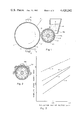
- FIG. 1 is a sectional view which illustrates the magnetic brush developing and cleaning process according to this invention.
- FIG. 2 is a cross-sectional view of the magnetic brush of FIG. 1 at the vicinity of magnet roll.
- FIG. 3 is a graph which illustrates the relation between the magnetic brush height and regulation gap of doctor.
- FIG. 4 is a sectional view which illustrates a mechanism for measuring the conveying ability of magnetic brush due to the magnet roll.
- FIG. 5 is a graph which illustrates the relation between the toner thickness and developing thickness.
- FIG. 6 is a graph showing the amounts of toner during the developing and cleaning steps.
- FIG. 1 is a schematic sectional view of a copying apparatus for providing one copy during two revolutions of an image bearing drum.
- the surface of a photosensitive drum 1 is formed with a photoconductive layer 1a.
- Drum 1 is turned to the direction as indicated by the arrow in the figure and there are arranged around the drum a corona electrifier 2 for electrifying uniformly the surface of photoconductive layer 1a, an optical system 3 for exposing the surface of photo-conductive layer 1a, magnetic brush forming equipment 4 and corona transferring equipment 5.
- the surface of photo-conductive layer 1a is electrified uniformly by means of corona electrifier 2 and then exposed to light by optical system 3 to form an elecrostatic latent image (not shown).
- the formed electrostatic latent image is then developed by means of magnetic brush 4 to form toner images 7' on the surface of photoconductive layer 1a.
- a transferring sheet 6 such as a conventional copying sheet is laminated on the developed toner images 7' and applied with transferring electric field from the rear surface of transferring sheet 6 by means of corona transferring equipment 5 to transfer toner images 7' onto transferring sheet 6.
- the transference is not limited to the use of such transferring electric field, but may be carried out by using an electrified roller.
- Toner images 7' are then fixed by pressure and/or heat or the like to provide a hard copy. However, not all of the magnetic toner is transferred onto the transferring sheet during the transference, and about 20% of the toner is normally remained on photoconductive layer 1a.
- the drum is confronted again with magnetic brush equipment 4 by the further revolution thereof so that the surface of drum is cleaned.
- magnetic brush equipment 4 Namely in the copying system as shown in FIG. 1, one hard copy is provided per two revolutions of the photoconductive drum.
- electricity removing means such as an AC corona electrifier and/or light source are provided between transferring equipment 6 and corona electrifier equipment 2 for improving the cleaning activity.
- Magnetic brush forming roller 4 includes non-magnetic shell 43 and permanent magnet roll 44.
- Non-magnetic cylindrical shell 43 is arranged rotatably proximate photoconductive drum 1.
- Magnet roll 44 is disposed rotatably within the shell 43 by supporting a cylindrical magnet having a plurality of magnetic poles by means of shaft 45 on the surface thereof.
- a toner vessel 41 in the form of a hopper and provided with a toner supplying opening at the bottom thereof and the toner vessel is fed with a magnetic developer, e.g. magnetic toner 7 therein.
- magnetic toner 7 is fed from toner supplying opening 41a onto the shell 43 and conveyed on the shell by relative rotation between permanent magnet roll 44 and shell 43, thereby forming magnetic brush 7a.
- the developing and cleaning processes are carried out.
- Magnetic brush 7a is formed by the magnetic toner on the surface of shell 43 in magnetic roll 4 and takes a form as shown in FIG. 2.
- the magnetic toner forms high bristles on the magnetic poles, N, S, N, . . . of magnet 44 and bridges between the bristles at the intervening zones between the poles.
- FIG. 3 illustrate the result of observation on the height of magnetic brush 7a on magnet roll 4 when the doctor gap proximate the lower portion of opening 41a for controlling the height of toner at the outlet of toner vessel 41 is varied.
- magnetic toner 7 will be conveyed on the shell counterclockwise.
- the height of magnetic brush 7a comprising the magnetic toner depicts Curves B and b as shown in FIG. 3, wherein B is the height up to the tip of bristles and curve b shows the height of bristles between the poles.
- the height of magnetic brush 7a is twice as high as that when only magnet 44 is turned.
- toner 7 is disposed on a magnetic brush forming roll 44 incorporating a shell having an outer diameter of 31.4 mm and a permanent magnet roll 46 having an outer diameter of 29.3 mm, 8 poles magnetized symmetrically and magnetic flux of 850 G on the shell.
- Cover glass 8 is installed above the toner layer by supporting fulcrum 9.
- a weight 10 is mounted on one end of cover glass 8 and is measured when the flow of toner is stopped to be defined as the conveying ability.
- FIG. 5 illustrates the developing conditions when the developing gap is varied with respect to the height of brush 7a of magnetic toner on shell 43. If the developing gap is smaller than the thickness of toner, since the amount of toner supplied to the developing zone is higher than that of toner passing through the developing zone, the toner will be accumulated upstream of the developing zone. If the developing gap is slightly larger than the toner thickness, the image bearing surface will be softly rubbed only by the tips of toner bristles to develop the electrostatic latent images on the shell. The optimum development is carried out when developing gap is larger by 0.05 to 0.20 mm than the toner thickness. When permanent magnet 44 is turned concurrently with shell 43, larger conveying ability is induced as disclosed hereinbefore, so that the image bearing surface is rubbed with large bristles to scrape away the toner on the image bearing surface.
- An excessively narrow developing gap D tends to accumulate the toner so that it is necessary to widen the developing gap to some extent. However, when the D is excessively wide, the toner fails to sufficiently contact the drum so that a sufficient concentration of copied images cannot be produced.
- the rotation of the permanent magnetic roll is preferably designed to be in a range of 5 to 20 times the peripheral speed of the photoconductive drum.
- relatively good development can be performed not only by rotating the magnet as referred to hereinabove, but also by rotating the shell in the same direction of rotating magnet at a relatively low speed.
- the conveying ability of toner is naturally larger than the case rotating the magnet but substantially smaller than the case rotating the shell.
- the toner conveying speed is the difference between the rotating speed of magnet and the revolving speed of shell so that the speed is relatively retarded.
- the peripheral speed of shell ranges preferably from 0.1 to 0.2 times of that of permanent magnet roll.
- the large magnetic brush is formed and the surface of drum is rubbed strongly by the formed magnetic brush, so that it is proposed to rotate the shell to the opposite direction to that of permanent magnet roll at a relatively higher speed during the cleaning step.
- the toner on the shell is affected by the concurrent actions of rotating force based on the alternating magnetic field due to the rotation of permanent magnet roll and friction force due to the rotation of shell, so that because of very enhanced toner conveying ability, the thickness of toner layer becomes higher than that in the case of magnet rotating system to form the larger magnetic brush.
- the toner on the shell is conveyed at a synthesized speed comprising the rotating speed of the magnet and the revolving speed of shell, the formed magnetic brush contacts strongly with the drum.
- the toner remaining on the drum is shifted from the position of drum to reduce the adhesion therewith and recovered easily into the magnetic brush to effect the sufficient cleaning.
- the peripheral speed of the shell is preferably designed to be approximately 1/7 to 1/10 of the rotating speed of permanent magnet roll.
- FIG. 6 illustrates time charts of the thicknesses of toner layer and toner pool during the developing and cleaning steps.
- the thickness of toner layer conveyed on the shell is reduced during the developing step, whereas the thickness is increased during the cleaning step.
- the amount of toner in the pool upstream of the developing gap shows a peak during the developing step but disappears substantially during the cleaning step.
- the permanent magnet roll is rotated at a constant speed in this invention, but the size of the magnetic brush and contacting condition with the drum are controlled depending on the developing step and cleaning step by adjusting variably the r.p.m. and the rotating direction of shell.
- the control can be effected easily and the actual workability is sufficient.
- a Se drum having a diameter of 120 mm was employed as the photoconductive drum and rotated at a speed of 150 mm/sec.
- the permanent magnet roll had an outer diameter of 29.3 mm and 10 magnetized symmetrical poles having a magnetic flux of 700 G on the shell and was rotated at 1200 r.p.m.
- As the shell a stainless steel cylinder having a diameter of 32 mm was employed.
- the used magnetic toner has specific resistivity of 10 14 ⁇ .cm and particle size ranging from 10 to 20 ⁇ m.
- the shell was rotated at 30 r.p.m. and during the cleaning step, it was rotated at 150 r.p.m. to provide subsequently up to 55 distinct copies capable of being put into practical use.
- the surface electicity on the drum was removed by applying an AC voltage of 5.5 kV by means of an AC corona electrifier means and then the cleaning was carried out in the above example.
Abstract
Description
Claims (5)
Priority Applications (1)
| Application Number | Priority Date | Filing Date | Title |
|---|---|---|---|
| US06/355,205 US4420242A (en) | 1982-03-05 | 1982-03-05 | Magnetic brush developing and cleaning process |
Applications Claiming Priority (1)
| Application Number | Priority Date | Filing Date | Title |
|---|---|---|---|
| US06/355,205 US4420242A (en) | 1982-03-05 | 1982-03-05 | Magnetic brush developing and cleaning process |
Publications (1)
| Publication Number | Publication Date |
|---|---|
| US4420242A true US4420242A (en) | 1983-12-13 |
Family
ID=23396615
Family Applications (1)
| Application Number | Title | Priority Date | Filing Date |
|---|---|---|---|
| US06/355,205 Expired - Fee Related US4420242A (en) | 1982-03-05 | 1982-03-05 | Magnetic brush developing and cleaning process |
Country Status (1)
| Country | Link |
|---|---|
| US (1) | US4420242A (en) |
Cited By (8)
| Publication number | Priority date | Publication date | Assignee | Title |
|---|---|---|---|---|
| US4571372A (en) * | 1983-04-22 | 1986-02-18 | Canon Kabushiki Kaisha | Method for coating a non-magnetic developer onto a developer holding member |
| US4595277A (en) * | 1983-02-01 | 1986-06-17 | Andrzej Maczuszenko | Toner supply control system |
| US4885612A (en) * | 1987-10-08 | 1989-12-05 | Ricoh Company, Ltd. | Cleaning device for an image forming apparatus |
| FR2640055A1 (en) * | 1988-12-03 | 1990-06-08 | Ricoh Kk | CLEANING METHOD FOR REMOVING FILM FROM DEPOSITS OF IMAGE MEDIA IN IMAGE GENERATING APPARATUS |
| FR2641623A1 (en) * | 1989-01-09 | 1990-07-13 | Ricoh Kk | Method making it possible to remove a film which has formed on an image support of an apparatus for forming an image |
| US4972233A (en) * | 1987-08-17 | 1990-11-20 | Canon Kabushiki Kaisha | Apparatus and method for cleaning a photosensitive member with spherical magnetic particles |
| US5581291A (en) * | 1990-11-26 | 1996-12-03 | Kyocera Corporation | Rear side exposure type electrographic image forming apparatus |
| US5717983A (en) * | 1994-02-09 | 1998-02-10 | Hitachi Metals, Ltd. | Simultaneous developing/cleaning method using magnetic support member |
Citations (8)
| Publication number | Priority date | Publication date | Assignee | Title |
|---|---|---|---|---|
| US3637306A (en) * | 1970-12-02 | 1972-01-25 | Ibm | Copying system featuring alternate developing and cleaning of successive image areas on photoconductor |
| US3914045A (en) * | 1973-04-30 | 1975-10-21 | Ricoh Kk | Method and apparatus for removing residual image from photoconductive element of electrophotographic copying machine |
| US4003651A (en) * | 1974-01-28 | 1977-01-18 | Konishiroku Photo Industry Co., Ltd. | System for recording images received by facsimile |
| US4014291A (en) * | 1976-01-26 | 1977-03-29 | Nashua Corporation | Image developing system |
| US4087170A (en) * | 1975-06-13 | 1978-05-02 | Tokyo Shibaura Electric Co., Ltd. | Electrostatic copying apparatus with combined charging transfer unit |
| US4141648A (en) * | 1976-12-15 | 1979-02-27 | International Business Machines Corporation | Photoconductor charging technique |
| US4185910A (en) * | 1976-06-30 | 1980-01-29 | Tokyo Shibaura Electric Co., Ltd. | Photoconductive member cleaning device using a magnetic brush for electrostatic copying machines |
| US4267248A (en) * | 1978-02-24 | 1981-05-12 | Hitachi Metals, Ltd. | Magnet-brush development process of electric pattern images |
-
1982
- 1982-03-05 US US06/355,205 patent/US4420242A/en not_active Expired - Fee Related
Patent Citations (8)
| Publication number | Priority date | Publication date | Assignee | Title |
|---|---|---|---|---|
| US3637306A (en) * | 1970-12-02 | 1972-01-25 | Ibm | Copying system featuring alternate developing and cleaning of successive image areas on photoconductor |
| US3914045A (en) * | 1973-04-30 | 1975-10-21 | Ricoh Kk | Method and apparatus for removing residual image from photoconductive element of electrophotographic copying machine |
| US4003651A (en) * | 1974-01-28 | 1977-01-18 | Konishiroku Photo Industry Co., Ltd. | System for recording images received by facsimile |
| US4087170A (en) * | 1975-06-13 | 1978-05-02 | Tokyo Shibaura Electric Co., Ltd. | Electrostatic copying apparatus with combined charging transfer unit |
| US4014291A (en) * | 1976-01-26 | 1977-03-29 | Nashua Corporation | Image developing system |
| US4185910A (en) * | 1976-06-30 | 1980-01-29 | Tokyo Shibaura Electric Co., Ltd. | Photoconductive member cleaning device using a magnetic brush for electrostatic copying machines |
| US4141648A (en) * | 1976-12-15 | 1979-02-27 | International Business Machines Corporation | Photoconductor charging technique |
| US4267248A (en) * | 1978-02-24 | 1981-05-12 | Hitachi Metals, Ltd. | Magnet-brush development process of electric pattern images |
Cited By (14)
| Publication number | Priority date | Publication date | Assignee | Title |
|---|---|---|---|---|
| US4595277A (en) * | 1983-02-01 | 1986-06-17 | Andrzej Maczuszenko | Toner supply control system |
| US4571372A (en) * | 1983-04-22 | 1986-02-18 | Canon Kabushiki Kaisha | Method for coating a non-magnetic developer onto a developer holding member |
| US4972233A (en) * | 1987-08-17 | 1990-11-20 | Canon Kabushiki Kaisha | Apparatus and method for cleaning a photosensitive member with spherical magnetic particles |
| US4885612A (en) * | 1987-10-08 | 1989-12-05 | Ricoh Company, Ltd. | Cleaning device for an image forming apparatus |
| FR2640055A1 (en) * | 1988-12-03 | 1990-06-08 | Ricoh Kk | CLEANING METHOD FOR REMOVING FILM FROM DEPOSITS OF IMAGE MEDIA IN IMAGE GENERATING APPARATUS |
| GB2225983A (en) * | 1988-12-03 | 1990-06-20 | Ricoh Kk | Method of removing a film from an image carrier |
| US5003354A (en) * | 1988-12-03 | 1991-03-26 | Ricoh Company, Ltd. | Method of removing a film from an image carrier of an image forming apparatus |
| GB2225983B (en) * | 1988-12-03 | 1992-06-24 | Ricoh Kk | Method of removing a film from an image carrier of an image forming apparatus |
| FR2641623A1 (en) * | 1989-01-09 | 1990-07-13 | Ricoh Kk | Method making it possible to remove a film which has formed on an image support of an apparatus for forming an image |
| US5581291A (en) * | 1990-11-26 | 1996-12-03 | Kyocera Corporation | Rear side exposure type electrographic image forming apparatus |
| US5717983A (en) * | 1994-02-09 | 1998-02-10 | Hitachi Metals, Ltd. | Simultaneous developing/cleaning method using magnetic support member |
| US5926677A (en) * | 1994-02-09 | 1999-07-20 | Hitachi Metals, Inc. | Image forming developing method |
| US6072974A (en) * | 1994-02-09 | 2000-06-06 | Hitachi Metals, Ltd. | Image forming developing method |
| US6075964A (en) * | 1994-02-09 | 2000-06-13 | Hitachi Metals, Ltd. | Image forming developing method |
Similar Documents
| Publication | Publication Date | Title |
|---|---|---|
| US4097140A (en) | Method and apparatus for cleaning toner in electrophotographic copying machines | |
| JPS5830585B2 (en) | Cleaning information | |
| US4482241A (en) | Device and method for stripping developer from a photoconductive surface | |
| US4420242A (en) | Magnetic brush developing and cleaning process | |
| JP2001242759A (en) | Cleaning device | |
| JPS6331780B2 (en) | ||
| JP3230019B2 (en) | Pre-charger | |
| JP3247164B2 (en) | Image forming device | |
| JPS58102278A (en) | Transfer device | |
| JP3333641B2 (en) | Roller transfer device in image forming apparatus | |
| JPH0224135Y2 (en) | ||
| JPS60103367A (en) | Developing device of electrophotografic copying machine | |
| JPS6286381A (en) | Developing device | |
| JPH04161965A (en) | Image forming device in electrophotographic system | |
| JPS6224293Y2 (en) | ||
| JP2000147873A (en) | Electrifier and image forming device | |
| JPS6246869B2 (en) | ||
| JPS589181A (en) | Cleaning device | |
| JP2852776B2 (en) | Image forming device | |
| JPH0962110A (en) | Transfer device | |
| JPS62279375A (en) | Electrophotographic developing device | |
| JPH0378629B2 (en) | ||
| JPH1184823A (en) | Contact type electrifying device | |
| KR970049142A (en) | Transfer roller cleaning devices for electrophotographic processors | |
| JPH0133827B2 (en) |
Legal Events
| Date | Code | Title | Description |
|---|---|---|---|
| AS | Assignment |
Owner name: HITACHI METALS, LTD., 2-1-2, MARUNOUCHI, CHIYODA-K Free format text: ASSIGNMENT OF ASSIGNORS INTEREST.;ASSIGNOR:YAMASHITA, KEITARO;REEL/FRAME:003991/0138 Effective date: 19820215 |
|
| MAFP | Maintenance fee payment |
Free format text: PAYMENT OF MAINTENANCE FEE, 4TH YEAR, PL 96-517 (ORIGINAL EVENT CODE: M170); ENTITY STATUS OF PATENT OWNER: LARGE ENTITY Year of fee payment: 4 |
|
| MAFP | Maintenance fee payment |
Free format text: PAYMENT OF MAINTENANCE FEE, 8TH YEAR, PL 96-517 (ORIGINAL EVENT CODE: M171); ENTITY STATUS OF PATENT OWNER: LARGE ENTITY Year of fee payment: 8 |
|
| FEPP | Fee payment procedure |
Free format text: PAYOR NUMBER ASSIGNED (ORIGINAL EVENT CODE: ASPN); ENTITY STATUS OF PATENT OWNER: LARGE ENTITY |
|
| FEPP | Fee payment procedure |
Free format text: PAYOR NUMBER ASSIGNED (ORIGINAL EVENT CODE: ASPN); ENTITY STATUS OF PATENT OWNER: LARGE ENTITY Free format text: PAYER NUMBER DE-ASSIGNED (ORIGINAL EVENT CODE: RMPN); ENTITY STATUS OF PATENT OWNER: LARGE ENTITY |
|
| FEPP | Fee payment procedure |
Free format text: MAINTENANCE FEE REMINDER MAILED (ORIGINAL EVENT CODE: REM.); ENTITY STATUS OF PATENT OWNER: LARGE ENTITY |
|
| LAPS | Lapse for failure to pay maintenance fees | ||
| FP | Lapsed due to failure to pay maintenance fee |
Effective date: 19951213 |
|
| STCH | Information on status: patent discontinuation |
Free format text: PATENT EXPIRED DUE TO NONPAYMENT OF MAINTENANCE FEES UNDER 37 CFR 1.362 |